2017 2nd International Conference on Information Technology and Industrial Automation (ICITIA 2017) ISBN: 978-1-60595-469-1
Study on Modeling and Simulation of
X-Swing-type Leg Hydraulic System of
Concrete Pump
Huiyong Liu and Qing Zhao
ABSTRACT
It is of importance for a truck mounted concrete pump to analyze its dynamic characteristics of X-Swing-type leg hydraulic system. According to the working principle of X-Swing-type leg hydraulic system of a truck mounted concrete pump, the simulation model of X-Swing-type leg hydraulic system is established based on AMESim, and the dynamic characteristics of X-Swing-type leg hydraulic system is analyzed. The research result provides some reference for design and improvement of X-Swing-type leg hydraulic system of a truck mounted concrete pump.
INTRODUCTION
Truck mounted concrete pump mainly consists of boom mechanism, pumping unit, rotation system, and leg hydraulic system. By the cooperation of boom mechanism, pumping unit and rotation system, the concrete can be transported to appropriate target position [1]. X-Swing-type leg hydraulic system of a truck mounted concrete pump is used to make all tires leave the ground and ensure it can be exempted the influence of dynamic construction load. Therefore, the X-Swing-type leg hydraulic system plays an essential role in concrete pumping process, and it is important to analysis the dynamic characteristics of the X-Swing-type leg hydraulic system.
________________________
Zhang Yanwei et al. [2] discussed the calculate method and general calculation formula of leg counter force. Kang Huimei [3] analyzed the leg counter force and lift displacement and gave corresponding calculation method. Tang Yongzhi et al. [4] introduced the design procedure of the bear range of front legs. Chen Guoan et al. [5] proposed the calculation method for solving the max possible leg counter force. AMESim, an advanced modeling and simulation environment for multi fields including mechanical, hydraulic, control, etc. [6], has been widely applied in many engineering fields such as renewable energy, hybrid system, et al.
This paper built the model of the X-Swing-Type leg hydraulic system of truck mounted concrete pump based on AMESim according to the working principle of the X-Swing-Type leg hydraulic system, and analyzed the dynamic characteristics.
WORKING PRINCIPLE OF X-SWING-TYPE LEG HYDRAULIC SYSTEM
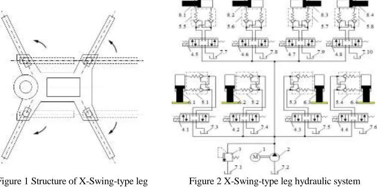
The X-Swing-type leg hydraulic system mainly consists of 4 legs, 4 leg vertical cylinders and 4 leg swing cylinders, etc., as shown in Fig. 1. The swinging of 4 legs is controlled by corresponding leg swinging cylinders. When the rods of the 4 leg swinging cylinders extend to a certain position, then under the action of the 4 leg vertical cylinders, all tires of a truck mounted concrete pump leave the ground, and guarantees it has sufficient safety and stability during pumping process.
[image:2.612.108.486.470.658.2]As shown in Fig. 2, the X-Swing-type leg hydraulic system includes engine, pump, pressure relief valve, bi-directional hydraulic lock, 4 leg vertical cylinders and 4 leg swing cylinders. When the X-Swing-type leg hydraulic system is working, firstly the 4 legs should be swung to the right position by means of the 4 leg swing cylinders, secondly the rods of 4 leg vertical cylinders extend to make all tires leave the ground thoroughly. The bi-directional hydraulic locks are used in each leg vertical cylinders and leg swing cylinders to ensure the safety and stability of a truck mounted concrete pump.
Figure 1 Structure of X-Swing-type leg Figure 2 X-Swing-type leg hydraulic system
SIMULATION MODEL OF X-SWING-TYPE LEG HYDRAULIC SYSTEM
On the base of working principle of X-Swing-type leg hydraulic system, by selecting appropriate components of engine, directional control valve, bi-directional hydraulic lock, and cylinders in AMESim, the simulation model of X-Swing-type leg hydraulic system is established, as shown in Fig. 3.
Figure 3. AMESim simulation model of X-Swing-type leg hydraulic system.
SIMULATION RESULTS AND ANALYSIS
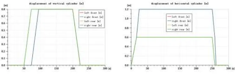
As shown in Fig. 4, when all piston rods of leg vertical cylinders are extending all leg vertical cylinders reach 0.8m using 22.5s, and the piston rods of rear leg vertical cylinders extend 22.5s earlier than the piston rods of front leg vertical cylinders. After the displacement of all leg vertical cylinders reach 0.8m and making all tires leave the ground, all leg vertical cylinders are locked by bi-directional hydraulic locks until the pumping work is finished. The piston rods of rear leg vertical cylinders withdraw with the piston rods of front leg vertical cylinders using same time 23.3s. As shown in Fig. 5, all piston rods of leg swing cylinders extend simultaneously, and rear leg swinging cylinders reach their setting stroke 0.6m in 16.25s, while front leg swinging cylinders reach their setting stroke 1.2m in 24.4s. After the displacement of front leg swing cylinders reach 1.2m and rear leg swinging cylinders reach 0.6m, all horizontal cylinders are locked respectively by bi-directional hydraulic locks until the pumping work is finished.
Figure 4. Displacement of leg vertical cylinders. Figure 5. Displacement of leg swing cylinders.
Figure 6. Velocity of leg vertical cylinders. Figure 7. Velocity of leg swing cylinders.
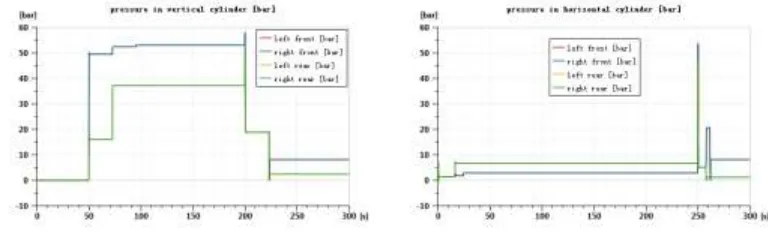
[image:5.612.126.489.86.202.2] [image:5.612.106.490.429.545.2]As shown in Fig. 8, when extending the pressure of rear and front leg vertical cylinders is 16bar and 49.5bar from the time of 50s and remains this value 22.5s, then turns to 37.2bar and 52.4bar at the time of 72.5s respectively. When withdrawing the pressure of all leg vertical cylinders is 18.9bar, then turns to 2.41bar and 8.16bar at the time of 223.5s respectively since the action of hydraulic locks. As shown in Fig. 9, when extending the pressure of rear and front leg swing cylinders is 1.46bar and lasts 16.2s, then the pressure of rear leg swinging cylinders and front leg swing cylinders turns to 6.74bar and 1.85bar respectively. It can be seen in Fig. 9 that when withdrawing the pressure of rear and front leg vertical cylinders is 5.17bar, then turns to 1.22bar and 20.63bar at the time of 257.8s respectively, then turns to 1.22bar and 8.16bar at 262s respectively since the action of hydraulic locks.
Figure 8. Pressure in leg vertical cylinders. Figure 9. Pressure in leg swing cylinders.
CONCLUSION
ACKNOWLEDGEMENT
This work was supported by the National Natural Science Foundation of China [grant number 51365008]; the Joint Foundation of Science and Technology Department of Guizhou Province [grant number Qiankehe LH Zi[2015]7658]. The authors gratefully acknowledge their support. Additionally, Liu Huiyong acknowledges the financial support from China Scholarship Council (CSC) to visit the Fluid-Structure Interaction Research Group (FSIRG) in the Faculty of Engineering and the Environment at the University of Southampton [grant number 201606675008].
REFERENCES
1. Zhang Guozhong: Modern concrete pump truck and its application technology in construction
(China Building Materials Press, China 2004).
2. Zhang Yanwei, Sun Guozheng, Shi Laide: Counterforce Calculation and Structure Analysis
Method of Concrete Pump’s Stabilizers. Chinese Journal of Construction Machinery, Vol.2(3) (2004), p. 253-258.
3. Kang Huimei: Analysis of concrete pump truck leg reaction force and the rising height.
Construction Machinery Technology & Management, Vol.4 (2002), p. 7-10.
4. Tang Yongzhi, Que Shenghua: Optimal design of X-style supports’ angle of concrete pump
truck. Construction Mechanization, Vol.2 (2011), p. 47-48.
5. Chen Guoan, Zhu Zhencai, Li Siding: Maximum loading calculation for construction machinery
outriggers. Chinese Journal Of Construction Machinery, Vol.8(2) (2010), p. 162-165.
6. Fu Yongling and Qi Xiaoye: System Modeling and Simulation Based on AMESim -- From