R E S E A R C H A R T I C L E
Open Access
Knee dGEMRIC at 7 T: comparison against
1.5 T and evaluation of T
1
-mapping
methods
Pernilla Peterson
1,2*, Carl Johan Tiderius
3, Emma Olsson
1, Björn Lundin
4, Lars E. Olsson
1,2and Jonas Svensson
1,4Abstract
Background:dGEMRIC (delayed Gadolinium Enhanced Magnetic Resonance Image of Cartilage) is a well-established technique for cartilage quality assessment in osteoarthritis at clinical field strengths. The method is robust, but requires injection of contrast agent and a cumbersome examination procedure. New non-contrast-agent-based techniques for cartilage quality assessment are currently being developed at 7 T. However, dGEMRIC remains an important reference technique during this development. The aim of this work was to compare T1mapping for dGEMRIC at 7 T and 1.5 T, and to evaluate three T1-mapping methods at 7 T.
Methods:The knee of 10 healthy volunteers and 9 patients with early signs of cartilage degradation were examined at 1.5 T and 7 T after a single (one) contrast agent injection (Gd-(DTPA)2−). Inversion recovery (IR) sequences were acquired at both field strengths, and at 7 T variable flip angle (VFA) and Look-Locker (LL) sequences were additionally acquired. T1 maps were calculated and average T1 values were estimated within superficial and deep regions-of-interest (ROIs) in the lateral and medial condyles, respectively.
Results: T1values were 1.8 (1.4–2.3) times longer at 7 T. A strong correlation was detected between 1.5 T and 7 T T1 values (r= 0.80). For IR, an additional inversion time was required to avoid underestimation (bias±limits of agreement
−127 ± 234 ms) due to the longer T1values at 7 T. Out of the two 3D sequences tested, LL resulted in more accurate and precise T1estimation compared to VFA (average bias±limits of agreement LL: 12 ± 202 ms compared to VFA: 25 ± 622 ms). For both, B1correction improved agreement to IR.
Conclusion:With an adapted sampling scheme, dGEMRIC T1mapping is feasible at 7 T and correlates well to 1.5 T. If 3D is to be used for T1mapping of the knee at 7 T, LL is preferred and VFA is not recommended. For VFA and LL, B1 correction is necessary for accurate T1estimation.
Keywords:dGEMRIC, Cartilage, 7 T, Inversion recovery, Variable flip angle, Look-locker
Background
Osteoarthritis is a common, painful, and disabling condition characterized by degradation and loss of cartilage. Although the disease progresses slowly, early detection is critical for development of treat-ment strategies which may prevent or slow down degradation before the cartilage is irreversibly lost.
The delayed Gadolinium Enhanced Magnetic Resonance Imaging of Cartilage (dGEMRIC) technique is a well-established method for early assessment of cartilage quality in osteoarthritis [1]. Using this technique, the distribution of Gd-(DTPA)2− contrast agent in cartilage after intravenous injection is assessed with quantitative T1
mapping. The estimated T1 is assumed to be indirectly
related to the content of glycosaminoglycan (GAG) which is known to decrease early in osteoarthritis. The method is robust and has proved to sensitively detect early degenerative cartilage processes [2, 3] and loss of cartilage quality [4]. However, the technique requires injection of contrast agent, which in addition to a cumbersome * Correspondence:[email protected]
1
Medical Radiation Physics, Department of Translational Medicine, Lund University, Inga Marie Nilssons gata 49, SE-205 02 Malmö, Sweden
2Department of Oncology and Radiation Physics, Skåne University Hospital,
Inga Marie Nilssons gata 49, SE-205 02 Malmö, Sweden Full list of author information is available at the end of the article
examination procedure may also lead to long-term gadolin-ium deposits [5]. Thus, current development of magnetic resonance imaging (MRI) methods for assessment of car-tilage quality is focused on methods that do not require contrast agent injection (e.g. GAG Chemical Exchange Saturation Transfer (gagCEST), 23Na imaging, T2
mapping, and T1ρ mapping [6]). In the development
process of these new techniques there is still a real need for an established method for cartilage quality evaluation to use as a reference. For this purpose dGEMRIC may still be the most suitable choice.
gagCEST and 23Na imaging benefit from the use of an ultra-high field strength, such as 7 T [7, 8]. Most dGEMRIC studies have so far been conducted at clinical field strengths. To enable the use of dGEM-RIC as a reference tool during the development of the new techniques, there is a need to first validate dGEMRIC also at 7 T.
Translating the dGEMRIC technique to an ultra-high field strength may have some advantages but there are also several challenges. Increasing the field strength increases the signal-to-noise ratio (SNR), which may be used to im-prove either the measurement precision or imaging reso-lution. However, a higher field strength also increases the expected T1values [9] and decreases the relaxivity of
Gd-(DTPA)2− [10]. These effects may require an altered dGEMRIC protocol and could reduce the sensitivity of the dGEMRIC experiment.
T1 mapping is a core component of the dGEMRIC
technique and several methods have been suggested in the literature. The gold standard approach is the 2D inversion recovery (IR) technique, but also 3D ap-proaches such as the variable flip angle (VFA) [11] and Look-Locker (LL) techniques have been increas-ingly used over the last years [12–14]. Several chal-lenges for accurate T1 measurements are expected
when moving to a higher field strength. First, the lon-ger T1values likely require longer inversion and
repe-tition times which increases the acquisition time. Second, the B1 field is likely more inhomogeneous at
ultra-high field strengths compared to clinical field strengths. This may affect the quality of the inversion pulse for the IR and LL experiments, but may also make B1 correction approaches necessary for the VFA
and LL techniques [14, 15]. For dGEMRIC at 7 T, IR [16] and VFA [17, 18] have previously been used for T1 mapping, but as no quantitative comparison
be-tween the methods has been performed, further inves-tigation is needed to find the optimal T1-mapping
approach at ultra-high field strength.
The aim of this study was to evaluate the feasibility of T1 mapping for knee dGEMRIC at 7 T by com-parison against 1.5 T in human subjects in vivo. In order to identify a preferred choice of T1-mapping
approach at the ultra-high field strength, we addition-ally aim to compare and evaluate three T1-mapping
techniques – IR, VFA, and LL.
Methods
Human subjects
The study was approved by the regional ethical re-view board and all human subjects gave their written informed consent. To increase the expected range of T1 values, both healthy volunteers (N= 10; 6 males,
4 females; median (range) age = 33.5 (23–56) years; body mass index (BMI) = 23.6 (20.7–26.3) kg/m2) and patients with early degenerative changes in the knee cartilage (N= 9; 6 males, 3 females; median (range) age = 42.9 (36–48) years; BMI = 30.1 (23.8–33.3) kg/m2) were included in the study. The inclusion criterion for the healthy volunteers was: No previous history of pain or other problem with the knee to be examined. Inclusion criteria for the patients were: superficial degenerative cartilage changes on the medial femoral condyle but no significant cartilage loss or fissuring deeper than 50% of the cartilage thickness as verified by arthroscopy conducted no more than 5 years before the MRI. The median time between arthroscopy and and imaging for the included subjects was 2.4 years (min 1.0 and max 2.8 years). Exclusion criteria for all subjects were: Kidney disease and implants which were not MRI compatible or risked induce artifacts.
Experiment procedure
Upon arrival at the hospital, an intravenous injection of a double dose (0.2 mmol/kg body weight) of Gd-(DTPA)2− (Magnevist®, Bayer Schering Pharma AG, Berlin, Germany) was administered. The subjects were then asked to walk at an easy pace along a specified path during 10 min to help distribution of the contrast agent in the cartilage [19].
in a wheel chair to minimize redistribution of the contrast agent in the knee joint between the examinations.
MRI examination
During the examinations, the knee was immobilized slightly bent in dedicated knee coils (1.5 T: receive only dStream Knee 15ch Coil, 7 T: transmit and receive QED Knee Coil 1TX / 28RX) using pads. A series of IR sequences with dif-ferent inversion times (TI) were acquired at both 1.5 T and at 7 T. 2D slices were centered over the medial and lateral condyle, respectively, and imaged in separate sequences (single slice). At 1.5 T, 6 TIs were acquired (TI = 50 ms, 100 ms, 200 ms, 400 ms, 800 ms, and 1600 ms). Other pa-rameters were: repetition time (TR) = 2000 ms, echo time (TE) = 7 ms, field of view (FOV) = 120x120x3 mm3, bandwidth = 402 Hz/pixel, echo train length = 11, matrix size = 256 × 256, and acquisition time (TA)/IR sequence = 46 s. The corresponding parameters for the 7 IR acquisitions at 7 T were TI = 50 ms, 100 ms, 200 ms, 400 ms, 800 ms, 1600 ms, and 3800 ms, TR = 4000 ms, TE = 7 ms, FOV = 120x120x3 mm3, bandwidth = 338 Hz/pixel, echo train length = 11, matrix size = 256 × 256, and TA/IR sequence = 1 min and 36 s. At 1.5 T a short diagnostic protocol was also executed in addition to the IR acquisition for all subjects. This was later used to exclude unexpected pathology and to aid in determining that the cartilage had adequate thickness for ROI evaluation.
At 7 T two different 3D T1 methods were
add-itionally evaluated: VFA and LL. For VFA, two 3D gradient echo sequences covering the knee joint were acquired with a non-selective excitation pulse and flip angles = 7° and 39°, TR = 30 ms, TE = 2.7 ms, FOV = 120 × 120 mm2, slice thickness = 3 mm, pixel bandwidth = 338 Hz, matrix size = 256 × 256, and TA/ sequence = 4–6 min depending on number of slices. The flip angles were optimized expecting a T1 of
700 ms [20]. For LL, a 3D gradient echo sequence was acquired with flip angle = 6°, TR = 5000 ms, time between each excitation pulse 5.5 ms, TE = 2.7 ms, FOV = 140x140x3 mm3, pixel bandwidth = 338 Hz, echo train length = 15, matrix size = 256 × 256, and TA = 13–15 min depending on number of slices. 24 inversion times were acquired ranging from 16 ms–3466 ms.
Finally, a Dual Refocusing Echo Acquisition Mode (DREAM) method for B1mapping [21] was acquired at 7 T
with: flip angle = 15°, TR = 5.7 ms, TE = 2.9 ms, FOV = 120 × 120 mm2, slice thickness = 3 mm, pixel bandwidth = 1695 Hz, matrix size = 120 × 110, and TA = 2–3 min depending on number of slices.
The acquisition of the IR sequences were priori-tized and were acquired in all subjects. In some cases the 7 T examinations were limited by time,
and for this reason both 3D sequences where not ac-quired in all subjects. VFA was acac-quired in 10 sub-jects (5 patients and 5 healthy subsub-jects) and LL in 14 subjects (5 patients and 9 healthy subjects). The total scan time for each volunteer was approximately 20 min at 1.5 T and 50 min at 7 T.
Estimation of T1maps
Voxel-based T1maps were created using the data from
the three different methods (IR, VFA, and LL) in home-written Matlab scripts (v. R2013b, Mathworks, Nattick, USA). When necessary, affine image registration using the imregister Matlab function was conducted between the various image sequences before further T1
estima-tion. The T1 calculations in the scripts were validated with phantom experiments using Ni-doped agarores gel phantoms with known T1 relaxation times before the start of this study (data not shown). The following calcu-lations were performed:
B1error estimation
The relative B1error (c), expressed as a fraction of the
nominal flip angle, was mapped using the DREAM se-quence as described above [21]. An average value (cROI) within the investigated region-of-interest (ROI) (see below) was estimated and used for correction of VFA and LL data.
IR
T1was estimated with a 3-parameter fit to Eq. (1) using a
Levenberg-Marquardt non-linear-least-squares algorithm:
STI ¼S0 1−ke− TI T1þe−
TR T1
ð1Þ
STIis the signal acquired at inversion timeTI,S0is the estimated signal atTI= 0, and kis the quality of the in-version pulse. A perfect inin-version pulse corresponds to k= 2.
For estimation of T1at 1.5 T, all six acquiredSTIwere
used. For 7 T, T1 was estimated both from the first six STIand from all sevenSTIs to investigate the importance of the additional longer TI at 7 T.
LL
From LL data (STI) the apparent T1(T1*), MA, and MB
were estimated in a 3-parameter fit to the following equation using a Levenberg-Marquardt non-linear-least-squares algorithm [22]:
STI ¼MA−MBe−
TI
T1 ð2Þ
For estimation of the actual T1the following equation
T1¼
1 1
T1þ
ln cosð ð ÞcαÞ
TR
ð3Þ
The nominal flip angle is represented by α, and the relative error of the flip angle is given by the factor c. Both B1-uncorrected (c= 1) and B1-corrected (c=cROI,
see above) T1values were estimated for comparison.
VFA
The T1 was estimated from the signals S1 and S2
ac-quired at the two flip anglesα1andα2according to [23]:
T1¼ TR
log
sinðcα1Þcosðcα2Þ−SS1 2
sinðcα2Þcosðcα1Þ
sinðcα1Þ−SS1 2
sinðcα2Þ 0
B B @
1 C C A
ð4Þ
A B1-uncorrected T1 was obtained by setting c= 1,
whereasc=cROIwas used for a B1-corrected T1.
Data analysis
Data analysis and ROI definition was performed in Matlab (v. R2013b, Mathworks, Nattick, USA). Two ROIs (one superficial and one deep) were drawn in each of the load-bearing lateral and medial femoral condyles for each field strength and method, respectively. Each ROI covered half the depth of the femoral cartilage from the center of the tibial plateau to the posterior boundary of the posterior meniscus. All ROIs were drawn by two readers to evaluate the variance in ROI definition. IR ROIs were drawn by Reader 1 and Reader 2 with 19 and 2 years of experience, respectively. VFA and LL ROIs were drawn by Reader 2 and Reader 3 (1 year of experi-ence). For the 3D sequences, care was taken to choose the slice that best matched the position of the IR slice. In addition, the adjacent two slices were also evaluated for both 3D approaches to investigate the uncertainty in-troduced by non-identical slice positioning. To exclude any possible extreme values, all values above 1300 ms (1.5 T) and 2600 ms (7 T) were disregarded when es-timating the average T1 within each ROI. In addition,
the average k factor was calculated within IR ROIs to investigate adiabatic pulse quality.
All estimated average T1 values within an ROI were
corrected for BMI differences between subjects with a reference BMI set to the mean value of all healthy sub-jects (BMI = 23.4 kg/m2) [24].
Statistical analysis
Statistical analysis was conducted in Matlab (v. R2013b, Mathworks, Nattick, USA) and for all statistical testing,
P< 0.05 was considered a significant result. Median and range were used for descriptive statistics.
To investigate a potential difference between start-ing at 1.5 T or 7 T, the relative T1 increase at 7 T
was compared between the groups starting at 1.5 T and 7 T using a Mann-Whitney U test. The Pearson correlation coefficient was used to estimate the cor-relation between T1 values at 1.5 T and 7 T. The
co-efficient of variation, defined as the ratio of the range and median T1 values in the healthy and patient
sub-ject groups, was used as a measure of variability. The differences in T1 values between healthy subjects and patients were tested for the various ROIs using a Mann-Whitney U test at both 1.5 T and 7 T. The quality of the fit for IR T1 calculations was estimated
as the standard error of the estimate (SEE) defined as the root of the averaged squared distance from the data points to the fitted line. The SEE was normalized to the estimated S0 and compared between using 6 and 7 TIs using a Wilcoxon signed rank test. A Wil-coxon signed rank test was also used to compare the average IR kfactors between 1.5 T and 7 T.
The measured T1 relaxation times are expected to be longer at 7 T than at 1.5 T. To be able to compare the average T1relaxation times from each ROI compartment
between field strengths, the T1 values were normalized
to the median value of all ROIs in healthy volunteers for the corresponding field strength. The resulting normal-ized T1values were compared between 1.5 T and 7 T for
each ROI using a Wilcoxon signed rank test.
Method agreement between VFA, LL, and IR were es-timated using linear regression and Bland-Altman ana-lysis. Slope, intercept, average bias, and limits of agreement were presented as measures of agreement. Inter-reader and inter-slice variability were measured as average bias and limits of agreement.
Results
The cartilage in all included subjects were deemed of ad-equate thickness for ROI evaluation in deep as well as superficial regions, based on the images from the diag-nostic acquisition and also directly from the images used for T1 evaluation. No cases of unexpected pathology was found.
Visually, the T1 values within ROIs of T1 maps
ob-tained with the IR sequence were regarded precise and homogenous, both from 1.5 T and 7 T (Fig.1). In con-trast, T1varied considerably within the ROI for the 3D
sequences (VFA and LL) in the healthy subject as well as the patient image examples.
The median T1 values obtained with IR at 1.5 T and
7 T for the various ROI and subject groups are pre-sented in Table1. As expected, longer T1values were
times longer 7 T T1s compared to those at 1.5 T. The
same overall patterns were observed at both field strengths with shorter T1values in superficial compared
to deep cartilage, and shorter T1in the medial compared
to the lateral condyle for both patients and healthy sub-jects. At both field strengths, patient T1 values were
slightly shorter and with a larger spread of values com-pared to healthy subjects. The difference between patient T1 values and healthy subjects T1 values were however not statistically significant. In the superficial medial re-gion the difference was close to significant both at 1.5 T (P= 0.11) and at 7 T (P= 0.09), whereas for all other ROI’s the test resulted in higherP-values (P> 0.25).
To be able to compare the T1 values at the two field
strengths, they were normalized to the median T1 in
healthy subjects at each field strength (Fig.2). The differ-ences in normalized T1values between 1.5 T and 7 T for
the various ROIs were all small, with a largest relative dif-ference of 10% in the superficial lateral region in patients.
The normalized T1 values were not statistically different
in most ROIs in neither patient (medial deep: P= 0.36, medial superficial: P= 0.16, lateral superficial: P= 0.13) nor healthy subjects (medial deep:P= 0.77, medial super-ficial: P= 0.70, lateral superficial: P = 0.70). The only ex-ception was the deep lateral ROI were the difference in normalized T1between field strengths was statistically
sig-nificant in patients (P= 0.04) and had a lowPvalue also in healthy subjects (P= 0.06).
The median (range) time between the medial IR se-quences at the two field strengths was 40 (28–63) minutes for healthy subjects and 40 (28–49) minutes for patients. To determine if this time difference would have impact on the comparison of the dGEMRIC results between the field strengths, the ratio of T1at 7 T and 1.5 T was compared
between healthy subjects first scanned at 1.5 T and at 7 T, respectively. The median (range) T1ratios when starting at
1.5 T / 7 T was 1.92 (1.51–2.05) / 1.67 (1.47–2.26) for the superficial ROIs and 1.82 (1.71–2.20) / 1.85 (1.72–1.99) for the deep ROIs. The difference was larger for superficial ROIs, but not statistically different for neither superfi-cial (P= 0.16) nor deep ROIs (P= 0.62). For this rea-son, we do not discriminate between in which order the measurements at the two field strengths were per-formed in the results presented here.
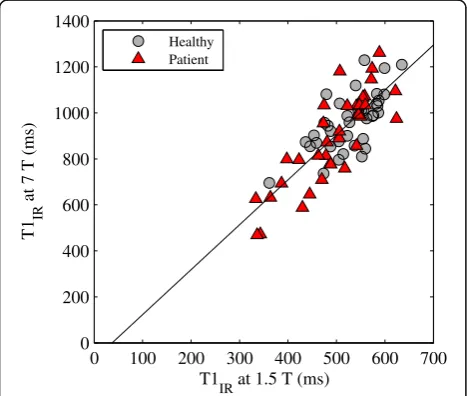
A linear correlation was found between the T1
values at 1.5 T and 7 T with a Pearson correlation coefficient of 0.80 (Fig. 3). The coefficient of variation at 1.5 T/7 T T1 s was 0.50/0.54 for healthy subjects
and 0.57/0.88 for patients, thus indicating a slightly larger spread of the 7 T T1 values, especially for
pa-tients. The inter-reader variability of the IR T1s was
[image:5.595.55.542.88.245.2]5.71 ± 49.2 ms at 1.5 T and−4.25 ± 96.1 ms at 7 T. The adiabatic pulse quality observed at 7 T was sig-nificantly lower compared to at 1.5 T with median (range) k factors equal to 1.85 (1.75–1.93) and 1.71 Fig. 1Example post-contrast T1maps overlaid on raw images acquired at 1.5 T and 7 T from a healthy volunteer (top row) and a patient (bottom row). As, expected longer T1values were measured at 7 T compared to 1.5 T. IR resulted in homogenous and precise T1 maps, whereas more variation was seen for the VFA and LL T1maps
Table 1Estimated T1values in the femoral condyles of study
subjects at the two field strengths
T1IRat 1.5 T (ms) T1IRat 7 T (ms)
Healthy (N= 10)
Medial Superficial 497 (361–562) 871 (695–1081)
Deep 534 (459–587) 967 (854–1229)
Lateral Superficial 530 (436–599) 944 (796–1080)
Deep 556 (488–635) 1042 (921–1209)
Patients (N= 9)
Medial Superficial 463 (336–522) 799 (469–1031)
Deep 507 (333–589) 984 (626–1261)
Lateral Superficial 541 (343–624) 890 (473–1068)
Deep 546 (364–622) 1029 (632–1193)
[image:5.595.56.291.570.723.2](1.11–1.89) at 1.5 and 7 T, respectively (P= 4·10−13). Of the 38 acquired IR data sets at each field strength, three data sets at 7 T had too low SNR for a voxel-by-voxel T1estimation due to a poor quality adiabatic
pulse. For these data sets, an ROI-based T1
estima-tion was performed.
Using the same six TIs at 7 T as used at 1.5 T results in lower T1values (bias ± limits of agreement−127 ± 234 ms)
and a lower quality fit with significantly higher SEE (median
SEE = 138 (20.9–1180) compared to SEE = 77.0 (29.4–524), P= 2·10−6) compared to using an adapted sampling scheme with an additional longer TI at 7 T (Fig.4). Thus, the presentation of 7 T T1results is based on the adapted
sampling scheme.
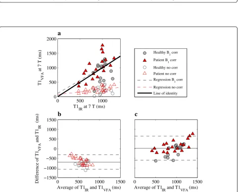
A poor agreement was observed between the T1values
measured with VFA and IR at 7 T (Fig.5 and Table 2). With no B1 correction the VFA technique severely
underestimated T1. Although the accuracy was improved
using a B1correction, the precision worsened with wider
limits of agreement. The inter-slice variability for the B1
-corrected case was −2.55 ± 433 ms and the inter-reader variability was −51.9 ± 327 ms. Both of these estimates of variability indicate a poor precision of the VFA method. Out of the 10 acquired VFA data sets, one was excluded due to technical difficulties during imaging.
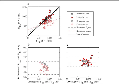
The LL T1 values agrees well with IR T1 values at
7 T (Fig. 6 and Table 2). Compared to VFA, LL both with and without B1 correction is more accurate and
precise. The agreement also for LL is improved using B1 correction, but the correction is not as vital as for
VFA. For the B1-corrected LL data, the inter-slice
variability was 1.33 ± 172 ms and the inter-reader variability was 11.5 ± 63.7 ms, thus indicating a smaller variability of LL data compared to VFA. Out of the 14 acquired LL data sets, five were excluded due to insufficient B0 shim causing a failed adiabatic
inversion pulse, and two were excluded due to tech-nical difficulties during imaging.
Discussion
This study compared dGEMRIC at 1.5 T and 7 T after a single (one) contrast-agent injection in both healthy Medial deep Medial superficial Lateral deep Lateral superficial
0 0.5 1 1.5 2
Normalized T1
IR
Healthy, 1.5 T Healthy, 7 T Patient, 1.5 T Patient, 7 T
Fig. 2Comparison of median normalized T1values at 1.5 T and 7 T in the various ROIs with error bars showing the range of values. The T1values were normalized to the median T1value of all healthy subject ROIs at 1.5 T and 7 T, respectively, to enable a comparison between the relaxation times at the two field strengths. Similar normalized T1values was seen at the two field strengths, and a significantly larger normalized T1at 7 T compared to 1.5 T was detected only in the deep lateral region in patients (P= 0.04)
0 100 200 300 400 500 600 700
0 200 400 600 800 1000 1200 1400
T1
IR at 1.5 T (ms)
T1
IR
at 7 T (ms)
Healthy Patient
[image:6.595.58.540.87.275.2] [image:6.595.57.291.465.663.2]0 500 1000 1500 0
500 1000 1500
a
T1
IR at 7 T (7 STI) (ms)
T1
IR
at 7 T (6 S
TI
) (ms)
Healthy Patient
0 500 1000 1500 −600
−400 −200 0 200 400
b
Average of using 6 and 7 S
TI (ms)
Difference of using 6 and 7 S
TI
(ms)
Fig. 4Scatter (a) and Bland-Altman plot (b) comparing IR T1values at 7 T using an adapted TI sampling with an additional longer TI (7 TIs) and the IR TI sampling pattern with 6 TIs. Ina) the line of identity is shown in solid black. Inb) the average bias and limits of agreement are shown in solid and dashed black lines, respectively. The T1values using 6 TIs were underestimated compared to using 7 TIs
0 500 1000 0
500 1000 1500 2000
T1IR at 7 T (ms)
T1
VFA
at 7 T (ms)
a
Healthy B
1 corr
Patient B
1 corr
Healthy no corr Patient no corr Regression B
1 corr
Regression no corr
Line of identity
0 500 1000 1500
c
Average of T1IR and T1VFA (ms) 0 500 1000 1500
−1500 −1000 −500 0 500 1000 1500
b
Average of T1IR and T1VFA (ms)
Difference of T1
VFA
and T1
IR
(ms)
[image:7.595.60.540.88.261.2] [image:7.595.58.540.294.683.2]subjects and patients. A randomized alternation of the 1.5 T and 7 T examinations of healthy subjects indicated that it was possible to obtain both measure-ments after a single contrast-agent administration without significant bias due to the difference in time delay after injection. Using an adapted sampling scheme with an additional longer TI, dGEMRIC based
on T1 measurements with IR is feasible at 7 T. The
estimated T1 values at the two field strengths were
strongly correlated, although there was a slightly wider distribution of the 7 T T1 s. Similar normalized
T1values were found using the two field strengths with
significant, yet small, difference between the two only for the deep lateral region. Out of the investigated 3D options at 7 T, LL showed a higher agreement to IR results com-pared to VFA. For both LL and VFA, B1correction is
ne-cessary at 7 T. Careful B0shimming is crucial, especially
for the IR and LL methods.
The feasibility of dGEMRIC at 7 T has previously been studied for knee [16] and hip applications [17, 18]. Our estimated postcontrast femoral T1 values are slightly
longer than those presented by Welsh et al. in healthy volunteers [16]. In expectation of longer T1 values at
[image:8.595.57.290.111.205.2]7 T, we chose to use an additional longer TI, compared to what was used in the Welsh study. The results from our study indicate that this choice is necessary to avoid underestimation of T1at 7 T.
Table 2Measures of method agreement between IR and the VFA and LL techniques
VFA LL
B1
correction No correction
B1
correction No correction
Bias ± limits of agreement (ms)
39.6 ± 640 −687 ± 389 12.2 ± 202 −239 ± 269
Slope ± 95% CI 0.90 ± 0.57 0.18 ± 0.18 0.88 ± 0.29 0.38 ± 0.29
Intercept ±95% CI (ms)
114 ± 537 74 ± 169 119 ± 265 326 ± 274
Regression and Bland-Altman analysis was used as measures of method agreement
0 500 1000 1500 0
500 1000 1500
a
T1IR at 7 T (ms)
T1
LL
at 7 T (ms)
Healthy B
1 corr
Patient B
1 corr
Healthy no corr
Patient no corr Regression B
1 corr
Regression no corr Line of identity
0 500 1000 1500
c
Average of T1
IR and T1LL (ms)
0 500 1000 1500 −600
−400 −200 0 200 400 600
b
Average of T1
IR and T1LL (ms)
Difference of T1
LL
and T1
IR
(ms)
[image:8.595.58.539.341.683.2]dGEMRIC has previously been compared between 7 T and a clinical field strength in repaired cartilage tissue of the hip, where dGEMRIC at 7 T resulted in an unex-pected T1decrease compared to dGEMRIC at 3 T [18].
Our study, however, resulted in the expected markedly longer T1values at 7 T compared to 1.5 T in native knee
cartilage of both healthy volunteers and patients. In the previous study [18], the VFA technique was used, while we in contrast chose an IR T1-mapping method for the
field strength comparison. Based on the evaluation of these techniques at 7 T presented in our current study, we believe that this resulted in a more accurate compari-son of T1values between field strengths.
VFA, LL, and IR have previously been compared at clinical field strengths [25]. Similarly to the results in this study, both the accuracy and precision of LL was su-perior to VFA also at 1.5 T. Previous studies using dGEMRIC at 7 T has used IR [16] and VFA [17, 18] for T1mapping. In a few healthy hips, these two techniques
have also been semi-quantitatively compared at 7 T and their respective measures were considered comparable [17]. Success of the VFA technique is dependent on an optimal choice of flip angle pair and B1-inhomogeneity
correction at high field strengths [11, 15]. Thus, at 7 T VFA is expected to be especially challenging as B1
in-homogeneity is likely high enough to also affect the opti-mal choice of flip angles. This issue may explain why VFA showed poor agreement with IR even after B1
cor-rection in our quantitative comparison.
The inversion pulses used in IR sequences were of bet-ter quality at 1.5 T compared to at 7 T in this study. This might be explained by the use of a transmit/receive coil at 7 T compared to a receive-only coil at 1.5 T. In addition, the adiabatic-type pulses rely on a successful B0 shim which is more challenging at 7 T. Especially,
this issue was apparent for the LL technique of which several data sets had to be excluded for this reason. However, also a few IR data sets suffered from poor SNR due to this problem. The B0-shim procedure was
im-proved during the course of the study, and after the volume-based first-order shim technique first used was replaced by use of the Shimtool [26] (an image-based second-order shim technique) the shim was sufficient in all the remaining LL data sets and the SNR of the remaining IR data sets were consistently high.
In our implementation, dGEMRIC using IR required a longer scan time at 7 T compared to at 1.5 T. The rea-son is that we, as we expected longer T1s at the higher
field strength, chose to increase the repetition time and add an extra acquisition with longer TI at 7 T. Our com-parison of using six and seven TIs for the T1estimation
demonstrates that this was necessary to achieve an ac-curate T1 estimation at 7 T. However, we also noticed
that the longer acquisition time made the sequences
more sensitive to patient motion as motion correction was more frequently needed in the 7 T scans as com-pared to the shorter 1.5 T scans. In a practical case when designing a study protocol it is important to take both the benefits and the potential disadvantages of a longer scan time into consideration.
Focus of this work was on the T1-mapping techniques
used for the dGEMRIC method at 7 T, and patients were primarily recruited to increase the expected range of T1
values. For this reason, a full comparison of dGEMRIC indices and diagnostic performance was beyond the scope of this study. However, although the difference in post-contrast T1 values between patients and healthy
volunteers was small (not statistically significant) in this study, it was similarly small at both 1.5 T and 7 T. At both field strengths it was the same region (superficial medial) that was closest to a significant difference, which is also the region were cartilage changes had been ob-served in the patients. The normalized T1 values were
also similar at the two field strengths. This hence implies that the methods perform similarly at the two field strengths. As possible explanation for the small differ-ences found, we speculate that the difference in timing between the protocols starting at 1.5 T and 7 T may have increased the spread of the data making compari-sons between groups more difficult.
dGEMRIC using Gd-(DTPA)2- (Magnevist) will probably be performed less frequently in the future given the fact that its use will be restricted based on the recent reports about long-term gadolinium deposits [5]. However, dGEMRIC could potentially also be used with other contrast agents such as gadoterate meglumine (Dotarem, Guerbet, Villepinte, France). To date almost all dGEMRIC studies have been performed using Mag-nevist, and future dGEMRIC studies with other contrast agents would of course first need careful and in depth validation studies. After such validation, the results from our evaluation of T1 mapping methods and field strength comparison would still be valuable for future studies with dGEMRIC at 7 T.
There were mainly two limitations of the study design of this work: the time difference between the examina-tions at the two field strengths and that no precontrast T1values were measured. Both for ethical and study
between 2 h and 3 h after injection [27]. Although no statistically significant difference in T1was found due to
timing differences in healthy volunteers, they may have increased the spread of the data as mentioned in the paragraph above. Precontrast T1 values were not
mea-sured neither at 1.5 T nor 7 T. This choice was made as the addition of these measurements would make the visit and scan time unbearably long for the study sub-jects. Instead, it was prioritized to make it feasible to perform the examinations at the two field strengths in a single visit and after a single contrast agent injection. Previous work indicates that the precontrast T1 value
contributes little additional information compared to postcontrast values at both 1.5 T and 3 T in native cartil-age [3,28]. In repaired cartilage tissue, measurements of precontrast T1 may be more important [29]. The
im-portance of a precontrast T1value may need to be
inves-tigated further also at 7 T.
Conclusions
In conclusion, T1 mapping for use in the dGEMRIC
method is feasible at 7 T with similar normalized T1
values compared to at 1.5 T and with a strong correl-ation between T1 values at 1.5 T and 7 T. However,
the IR protocol at 7 T needs to be adapted to the longer T1 values at this field strength. As a 3D
alter-native to IR at 7 T, LL is preferred and VFA is not recommended without further optimization of the method. For both 3D methods, B1 correction is
ne-cessary for an accurate T1 estimation. For LL and IR,
careful B0 shimming is crucial at 7 T.
Abbreviations
BMI:Body mass index; CEST: Chemical exchange saturation transfer; dGEMRIC: Delayed gadolinium enhanced magnetic resonance imaging of cartilage; DREAM: Dual refocusing echo acquisition mode; FOV: Field of view; GAG: Glycosaminoglycan; IR: Inversion recovery; LL: Look-locker;
MRI: Magnetic resonance imaging; ROI: Region of interest; SEE: Standard error of the estimate; TE: Echo time; TI: Inversion time; TR: Repetition time; VFA: Variable flip angle
Acknowledgments
We would like to thank the staff at the Swedish National 7 T Facility, especially Boel Hansson, Johanna Arborelius, and Karin Markenroth Bloch, for their invaluable help.
Funding
This research was supported by the Swedish Research Council [grant number K2013-52X-22196-01-3] and Greta och Johan Kocks stiftelser.
Availability of data and materials
The data used and/or analyzed during the current study are available from the corresponding author on reasonable request. However, imaging data will not be publicly shared to not compromise the study subject privacy.
Authors’contributions
The study was conceived and designed by PP, CJT, LEO, and JS. Data was acquired by PP and EO, and the acquired images were read and inspected by BL. Analysis of the data was conducted by PP, CJT, and EO. The manuscript was drafted by PP. All authors contributed to interpretation of
the results and critical review of the manuscript. All authors have read and approved the manuscript.
Ethics approval and consent to participate
The study was approved by the Lund regional ethical review board (2015/ 371) and all human subjects gave their written informed consent.
Competing interests
The authors declare that they have no competing interests.
Publisher’s Note
Springer Nature remains neutral with regard to jurisdictional claims in published maps and institutional affiliations.
Author details
1
Medical Radiation Physics, Department of Translational Medicine, Lund University, Inga Marie Nilssons gata 49, SE-205 02 Malmö, Sweden.
2Department of Oncology and Radiation Physics, Skåne University Hospital,
Inga Marie Nilssons gata 49, SE-205 02 Malmö, Sweden.3Orthopedics,
Department of Clinical Sciences, Lund University, Skåne University Hospital, SE-221 85 Lund, Sweden.4Department of Medical Imaging and Physiology,
Skåne University Hospital, SE-221 85 Lund, Sweden.
Received: 17 January 2018 Accepted: 30 April 2018
References
1. Bashir A, Gray ML, Burstein D. Gd-DTPA2- as a measure of cartilage degradation. Magn Reson Med. 1996;36(5):665–73.
2. Owman H, Tiderius CJ, Neuman P, Nyquist F, Dahlberg LE. Association between findings on delayed gadolinium-enhanced magnetic resonance imaging of cartilage and future knee osteoarthritis. Arthritis Rheum. 2008; 58(6):1727–30.
3. Tiderius CJ, Olsson LE, Leander P, Ekberg O, Dahlberg L. Delayed gadolinium-enhanced MRI of cartilage (dGEMRIC) in early knee osteoarthritis. Magn Reson Med. 2003;49(3):488–92.
4. Tiderius CJ, Svensson J, Leander P, Ola T, Dahlberg L. dGEMRIC (delayed gadolinium-enhanced MRI of cartilage) indicates adaptive capacity of human knee cartilage. Magn Reson Med. 2004;51(2):286–90. 5. Fraum TJ, Ludwig DR, Bashir MR, Fowler KJ. Gadolinium-based contrast
agents: a comprehensive risk assessment. J Magn Reson Imaging. 2017; https://doi.org/10.1002/jmri.25625.
6. Trattnig S, Zbyn S, Schmitt B, Friedrich K, Juras V, Szomolanyi P, et al. Advanced MR methods at ultra-high field (7 tesla) for clinical musculoskeletal applications. Eur Radiol. 2012;22(11):2338–46. 7. Singh A, Haris M, Cai K, Kassey VB, Kogan F, Reddy D, et al. Chemical
exchange saturation transfer magnetic resonance imaging of human knee cartilage at 3 T and 7 T. Magn Reson Med. 2012;68(2):588–94.
8. Staroswiecki E, Bangerter NK, Gurney PT, Grafendorfer T, Gold GE, Hargreaves BA. In vivo sodium imaging of human patellar cartilage with a 3D cones sequence at 3 T and 7 T. J Magn Reson Imaging. 2010;32(2):446–51. 9. McKenzie CA, Williams A, Prasad PV, Burstein D. Three-dimensional delayed
gadolinium-enhanced MRI of cartilage (dGEMRIC) at 1.5T and 3.0T. J Magn Reson Imaging. 2006;24(4):928–33.
10. Rohrer M, Bauer H, Mintorovitch J, Requardt M, Weinmann HJ. Comparison of magnetic properties of MRI contrast media solutions at different magnetic field strengths. Investig Radiol. 2005;40(11):715–24.
11. Mamisch TC, Dudda M, Hughes T, Burstein D, Kim YJ. Comparison of delayed gadolinium enhanced MRI of cartilage (dGEMRIC) using inversion recovery and fast T1 mapping sequences. Magn Reson Med. 2008;60(4):768–73.
12. Kimelman T, Vu A, Storey P, McKenzie C, Burstein D, Prasad P. Three-dimensional T1 mapping for dGEMRIC at 3.0 T using the look locker method. Investig Radiol. 2006;41(2):198–203.
13. Li W, Scheidegger R, Wu Y, Vu A, Prasad PV. Accuracy of T1 measurement with 3-D look-locker technique for dGEMRIC. J Magn Reson Imaging. 2008; 27(3):678–82.
14. Siversson C, Tiderius CJ, Dahlberg L, Svensson J. Local flip angle correction for improved volume T1-quantification in three-dimensional dGEMRIC using the look-locker technique. J Magn Reson Imaging. 2009;30(4):834–41. 15. Siversson C, Chan J, Tiderius CJ, Mamisch TC, Jellus V, Svensson J, et al.
angle T1 measurements in hip dGEMRIC at 3 T and 1.5 T. Magn Reson Med. 2012;67(6):1776–81.
16. Welsch GH, Mamisch TC, Hughes T, Zilkens C, Quirbach S, Scheffler K, et al. In vivo biochemical 7.0 tesla magnetic resonance: preliminary results of dGEMRIC, zonal T2, and T2* mapping of articular cartilage. Investig Radiol. 2008;43(9):619–26.
17. Lazik A, Theysohn JM, Geis C, Johst S, Ladd ME, Quick HH, et al. 7 tesla quantitative hip MRI: T1, T2 and T2* mapping of hip cartilage in healthy volunteers. Eur Radiol. 2016;26(5):1245–53.
18. Lazik-Palm A, Kraff O, Johst S, Quick HH, Ladd ME, Geis C, et al. Morphological and quantitative 7 T MRI of hip cartilage transplants in comparison to 3 T-initial experiences. Investig Radiol. 2016;51(9):552–9. 19. Burstein D, Velyvis J, Scott KT, Stock KW, Kim YJ, Jaramillo D, et al. Protocol
issues for delayed Gd(DTPA)(2-)-enhanced MRI (dGEMRIC) for clinical evaluation of articular cartilage. Magn Reson Med. 2001;45(1):36–41. 20. Deoni SC, Rutt BK, Peters TM. Rapid combined T1 and T2 mapping
using gradient recalled acquisition in the steady state. Magn Reson Med. 2003;49(3):515–26.
21. Nehrke K, Bornert P. DREAM–a novel approach for robust, ultrafast, multislice B(1) mapping. Magn Reson Med. 2012;68(5):1517–26. 22. Deichmann R, Haase A. Quantification of T1 values by snapshot-flash Nmr
imaging. J Magn Reson. 1992;96(3):608–12.
23. Homer J, Beevers MS. Driven-equilibrium single-pulse observation of T1 relaxation - a reevaluation of a rapid new method for determining Nmr spin-lattice relaxation-times. J Magn Reson. 1985;63(2):287–97. 24. Tiderius C, Hori M, Williams A, Sharma L, Prasad PV, Finnell M, et al.
dGEMRIC as a function of BMI. Osteoarthr Cartil. 2006;14(11):1091–7. 25. Siversson C, Tiderius CJ, Neuman P, Dahlberg L, Svensson J.
Repeatability of T1-quantification in dGEMRIC for three different acquisition techniques: two-dimensional inversion recovery, three-dimensional look locker, and three-three-dimensional variable flip angle. J Magn Reson Imaging. 2010;31(5):1203–9.
26. Schar M, Kozerke S, Fischer SE, Boesiger P. Cardiac SSFP imaging at 3 tesla. Magn Reson Med. 2004;51(4):799–806.
27. Tiderius CJ, Olsson LE, de Verdier H, Leander P, Ekberg O, Dahlberg L. Gd-DTPA2- -enhanced MRI of femoral knee cartilage: a dose-response study in healthy volunteers. Magn Reson Med. 2001;46(6):1067–71.
28. Williams A, Mikulis B, Krishnan N, Gray M, McKenzie C, Burstein D. Suitability of T(1Gd) as the dGEMRIC index at 1.5T and 3.0T. Magn Reson Med. 2007;58(4):830–4.