2018 International Conference on Computational, Modeling, Simulation and Mathematical Statistics (CMSMS 2018) ISBN: 978-1-60595-562-9
Simulation and Analysis of Leakage Magnetic Field of PMSM
Based on Comsol Multiphysics
Gui HU, Qi ZHANG
*, Meng-chun PAN, Cheng-biao WAN and Zhong-yan LIU
College of Artificial Intelligence, National University of Defense Technology, Changsha, 410073, China
*Corresponding author
Keywords: PMSM, Leakage magnetic field, Simulation.
Abstract. When using rotary aircraft equipped with three-axis magnetometer for measurement, the magnetometer is often affected by the leakage magnetic field from the permanent magnet synchronous motor (PMSM) on the aircraft. The analysis of the characteristics of the leakage magnetic field of PMSM is helpful for the determination of the installation position of the magnetometer and cancellation of the interference of the leakage magnetic field when measuring the external environment magnetic field. In this paper, a three-dimensional PMSM model has been simulated by using Comsol Multiphysics software, and the leakage magnetic field of the motor was investigated. According to the simulation results, we find that the phase of the leakage magnetic field varies linearly around the center of the motor in space, and the amplitude decays exponentially in different directions.
Introduction
Geomagnetic field is one of the important geophysical fields. It has complex spatial structure and time evolution [1]. Geomagnetic field measurement has great significance in aerospace, resource exploration, traffic, national defense, earthquake prediction, space weather and environmental monitoring, etc. [2]. Aeromagnetic survey using high-precision magnetometers and unmanned rotorcraft is a widely used method for its high speed and low cost [3]. However, this method is susceptible to the complex electromagnetic interference of rotorcraft and greatly affects magnetometer measurement accuracy. In order to facilitate effective compensation and suppression, it is necessary in order to fully analyze the magnetic field characteristics. By analyzing the structure and material properties of the rotorcraft, it is known that the main source of magnetic interference is the motor, and the leakage magnetic field outside the motor casing is one of the main factors [4].
At present, the shielding cover on the motor is mainly adopted to reduce the influence of the leakage magnetic field of the motor [5, 6]. However, this method would undoubtedly increase the motor size. In some research groups, filters are utilized to remove the motor leakage magnetic field signal [7], but some useful signals are also inevitably filtered out. The magnetic field of the motor rotates at a fixed frequency in the space [8], so a certain magnetic field outside the motor can be regarded as a sinusoidal signal which changes with time. If the law of phase and amplitude of the magnetic field can be obtained as a function of space, the magnetic field of the motor at any position outside the shell can be determined, so that the interference of the magnetic field can be accurately removed from the total signal. Therefore, this paper uses Comsol Multiphysics finite element software to model and simulate the leakage magnetic field of the motor, and studies the variation law of the leakage magnetic field, which lays the groundwork for subsequent.
Parameter of the Motor
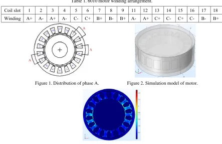
slots. The slot windings of the 6010 type motor are given in table 1, and the corresponding A-phase windings are shown in Figure 1.
Table 1. 6010 motor winding arrangement.
Coil slot 1 2 3 4 5 6 7 8 9 11 12 13 14 15 16 17 18 Winding A+ A- A+ A- C- C+ B+ B- B+ A- A+ C+ C- C+ C- B- B+
Figure 1. Distribution of phase A. Figure 2. Simulation model of motor.
Figure 3. Motor magnetic field distribution.
Modeling and Simulation
The simulation model of PMSM is established by Comsol software. As shown in Figure 2 the model mainly includes a rotor and a stator. The magnetic field distribution of the motor at a time is given in Figure 3. From the figure we can see the distribution of the motor magnetic field.
The air gap magnetic flux waveform of one circle of the motor is shown in Figure 4. It can be seen that the motor air gap magnetic field frequency is consistent with the current frequency. According to the principle of PMSM, the rotor speed is determined by the frequency of the coil current, and the relationship is as follows:
p f
n60 / . (1)
[image:2.612.97.518.613.724.2]The Law of the Amplitude and Phase of the Leakage Magnetic Field in Space The Law of Phase
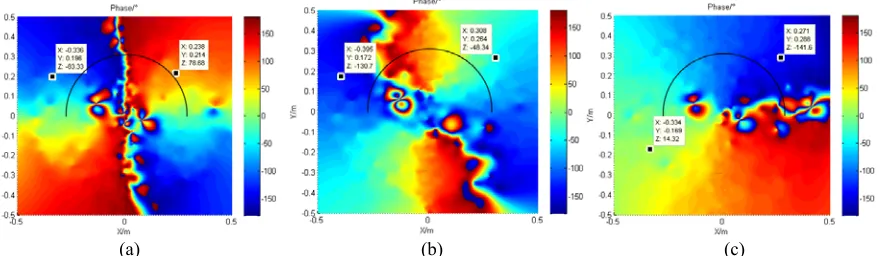
A magnetic field that rotates in space is generated, when a balanced three-phase current is injected into the three-phase symmetrical winding of the PMSM. At the same time, the leakage magnetic field also changes in rotation, and its frequency is in line with the primary frequency magnetic field of the motor. To derive the variation law of the leakage magnetic field of the motor, the change of the amplitude and phase of the leakage magnetic field should be taken into account as a function of position. A rectangular coordinate system is created in the center of the motor so that the xoy plane is parallel to the horizontal plane of the motor and the z-axis is perpendicular to the plane. Figure 6 shows the phase values of the three components of the magnetic field at each point in the yoz plane. It can be seen that the phase change of Bx on the yoz plane is small, with an average of 170.1°. The average phase of By in the semi-circular area on the right and left sides of the motor is 74.1°, and the other areas are -101.8°. The phase of Bz is -104.4° in the upper left and lower right rectangular areas of the motor, and the other two areas are 76.2°. Such a regularity of the phase has to be in conformity with theoretical expectations, which can be explained by Figure 5. The figure shows the distribution of the magnetic field vector on the yoz plane at the initial moment. It can be observed that the magnetic field rotate around the motor on both sides of the motor.
[image:3.612.89.529.304.432.2](a) (b) (c)
Figure 6. The phase of the components of the magnetic field on the yoz plane. (a) Bx component.
(b) By component. (c) Bz component.
(a) (b) (c)
Figure 7. The phase of the components of the magnetic field on the x’o’y’ plane. (a) Bx component.
[image:3.612.90.530.468.596.2](a) (b) (c)
Figure 8. Changes in phase on a semicircle. (a) Bx component. (b) By component. (c) Bz component.
The changes in the phase of the magnetic field at other positions can be briefly summarized by taking a plane directly below the motor. Figure 7 is the phase of the x'o'y' plane at 0.1 m from the lower surface of the motor. A semicircle with a radius of 0.3 m is drawn in these phase diagrams. Phase changes in the semicircle are shown in Figure 8. It can be observed that the phase changes linearly along the circular arc, that is, the phase changes linearly around the center. Moreover, the phase of Bx and By change by 360° in the semicircle, the phase of Bz changes by 180°, and the other semicircle is the same. It should be noted that the maximum and minimum phases of some positions in the figure are 180° and -180°, respectively. For phase, they are equal.
In combination with the above rules, the phase at any position in space is obtained by rotating counterclockwise with the z-axis as the center and taking the phase of the yoz plane as the initial value. And in the rotation process, the phase decreases linearly.
(a) (b) (c)
(d) (e) (f)
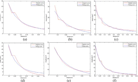
Figure 9. Fitting of amplitude attenuation. (a) Fitting of Bx's amplitude in the horizontal direction. (b) Fitting of Bx's
amplitude in the vertical direction. (c) Fitting of Bx's amplitude in the oblique direction. (d) Fitting of By's amplitude in the horizontal direction. (e) Fitting of By's amplitude in the vertical direction.
(f) Fitting of Bz's amplitude in the oblique direction.
[image:4.612.85.530.366.629.2]that magnetic objects can be treated as magnetic dipoles in space more than 2.5 times the length of the object [9]. The magnetic dipole model is as follows:
5 2
0 3( )
4 r
Mr r r M
B
. (2) Where, μ0 is the vacuum permeability, r is the distance, and M is the magnetic moment of the magnetic dipole. The attenuation of the magnetic field is substantially reduced by an exponential function with an exponent of -3. Therefore, this paper takes the exponential function fitting on the amplitude in the horizontal, vertical and oblique directions. The exponential function used is as follows:
k Ar
B . (3) Where, B is the modulus of the component, A represents the initial coefficient and k represents the decay index. The magnetic field at three times the length of the motor is fitted with the above function. The fitting situation is shown in Figure 9, and the resulting attenuation index is shown in Table 2. The position of the slashes in the table is not fitted due to the area where the amplitude difference is as large as the difference mentioned above.
From the table, it can be seen that the attenuation of the magnetic field amplitude on the line is consistent with the magnetic dipole model, i.e., a magnetic field three times the length of the magnet is approximately exponentially decayed with an index of -3. The attenuation of Bx is close to -2 at the three lines and the attenuation of By at the vertical line is also close to -2. By analyzing the magnetic field, it can be known that when the magnetic field vector on the yoz plane is parallel to the x-axis, the amplitude of Bx gets the maximum value. And when the amplitude of By on the yoz plane takes the maximum, the magnetic field vector on the vertical line is also parallel to the y-axis. At the same time, it can be found that these attenuation paths are perpendicular to the direction of the magnetic field vector. That is, when the magnetic field attenuation is studied along the direction perpendicular to the magnetic field vector, the attenuation index is less than -3, which can be also available by simulating a typical magnetic dipole model.
From the above, the amplitude of the Bx component decays exponentially with -2 in three directions, the By decays exponentially with -3 in the horizontal direction, -2 in the vertical direction, and Bz decays in the oblique direction by -3. From these laws, the magnitude of the leakage magnetic field at any location can be known.
Table 2. Leakage magnetic field attenuation exponent.
attenuation exponent Bx By Bz
horizontal -2.051 -2.911 \
vertical -1.962 -1.989 \
oblique -2.118 \ -3.356
Summary
References
[1] Merrill, R.T, The magnetic field of the earth: paleomagnetism, the core, and the deep mantle, Eos Transactions American Geophysical Union. 50(1997), 70-70.
[2] Peng Fuqing, Mao Xuejun. Review on Geomagnetic Surveying and Application. Geomatic Science and Engineering. 26 (2006) 53-56.
[3] Xu Wenyao, Physics of Electromagnetic Phenomena of the earth, First ed., University of Science and Technology of China Press, China, 2009.
[4] Li Xinjue, Electromagnetic Performance Analysis and Magnetic Flux Leakage Research on Permanent Magnet Motor for Manipulator [D], Harbin Institute of Technology, 2017.
[5] Li Jiming, Hu Yuli, Magnetic Field Analysis of Permanent Magnet DC Motor with Different Shields, Small & Special Electrical Machines. 8 (2011) 19-22.
[6] Zhang Lei, Lin Mingyao, Li Xin, Finite Element Processing Method to the Peripheral Leakage Magnetic Field of PM Machine, explosion-proof electric machine. 44 (2009) 24-28.
[7] Liu Zhe, Brushless DC Motor Interference Analysis of Magnetic Measurements and Compensation Technology Research [D], Huazhong University of Science & Technology, 2012. [8] Editorial board, China Electric Power Encyclopedia, third ed., China Electric Power Press, China, 2014.