2018 International Conference on Computer, Communication and Network Technology (CCNT 2018) ISBN: 978-1-60595-561-2
Development of a Virtual Equipment Training System
Based on Multi-platform Integration
Cheng-wei JIANG*, Xing-wu KANG, Xu-ping WANG and Jun-kang CHEN
Xi'an High-tech Research Institute, Shanxi 710025, China
*Corresponding author
Keywords:Unity3D,Multi-platform integration, Decomposition and reinstalling.
Abstract. Aiming at the shortcomings of the existing equipment virtual training system and simulation system development platform, which is backward and the simulation effect is poor, the development of a multi-platform integrated virtual training system for a certain equipment is put forward. Through the 3Dsmax geometric model modeling and behavior modeling of Unity3D platform equipment equipment operators, to achieve the basic functions of virtual training system, and combined with other software development characteristics and advantages, the advantages of Flash applied to the virtual training system of equipment. The results show that: It is entirely feasible to develop a virtual training system based on the Unity3D platform. Combined with the combination of 3Dsmax and Flash, the effect of a certain type of equipment simulation is more realistic than the previous single platform, and the human-computer interaction experience is better and can be widely used. It is used in virtual assembly and disassembly training and virtual maintenance of complex equipment.
Introduction
The constant innovation of various simulation platform technologies has made the physical simulation of large-scale complex equipment more and more simple, and it has also become increasingly rich in the virtual operation functions of large-scale equipment. However, the continuous technical revolution in the Internet field has led to the development of simulation systems and virtual training systems that are facing a backward technology. Virtools, NGRAIN, Vega and other simulation platform tools are already relatively backward technological means. In contrast, Unity3D, as a mainstream game development software platform, has the advantages of rich functions, various types of graphics engines, good compatibility, and a large selection of development languages, allowing visual developers to easily create 3D scenes and numbers. Visual content [1-2] for entertainment games, building visualization, etc., so the use of Unity3D becomes more and more frequent in the application of visual simulation of large complex equipment [3]. At the same time, Unity3D is a comprehensive visual development tool that supports multi-platform publishing. It is also a 3D production engine with rich functions. Combining Unity3D with other modeling platforms and interactive interface video production platforms, it can be used as the main platform in the virtual simulation of complex equipment.
System Module Composition
Overall equipment model Structural component Component selection Model dynamic analysis Joining of components Equipment structure recognition Selection of components Choice of operator type Familiar with the operating specifications Steps to achieve Judging the correctness or error Complete the virtual decomposition and reinstall
The module of decomposition and reinstall Structural Cognitive Module User login Module selection User Management Record inquiry Special tools Overall
equipment GUI module
System user
V
I
R
T
U
A
L
S
Y
S
T
E
m
Figure 1. Overall system structure.
Development of Virtual Training System
Figure 2. Technology Roadmap.
The equipment simulation system based on Unity3D is composed of three modules. The design of the Graphical User Interface (GUI) module, the structural modeling of the structure recognition module, and the behavior modeling of the disassembly and reassembly module are completed separately. Select the appropriate collision detection solution, and finally integrate three complete modules to optimize the system and complete the development of the entire system. Figure 2 shows a multi-platform technology roadmap for the development of a virtual training system. The specific steps are as follows.
GUI Design
The design of the GUI is mainly implemented through a scripting language. At the same time, you can also write your own editor script to develop your own GUI editor. The GUI code needs to be called in the OnGUI function. The GUI control needs to pass in the Rect parameter to set the drawing area of the screen, for example Rect (10,30,250,350). The corresponding screen area is the coordinates of the upper left corner (10, 30). The width is 250 and the height is 350. In Unity 3D's GUI control, the coordinate of the screen is the origin in the upper left corner. This system realizes the user login interface and function selection interface through the programming of ONGUI script language. The system user logs in with the login password. After the login is successful, the function module can be selected.
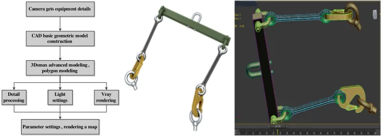
Structural Modeling of Equipment and Special Tool
The core and simulation object of the virtual training system is the model, which mainly includes the models of equipment and special tools. 3Dsmax is usually used in conjunction with CAD to achieve model modeling through CAD model-aided design and 3Dsmax post-detail processing. The specific steps are first to build the basic geometric model through the graphical command; then use the advanced modeling in the 3Dsmax to process the model in detail; after the details of the model are processed, the light and the camera are used to adjust the visual effects of each perspective; The vray renderer is turned on, and the texture is mapped according to the material of the model, giving a real physical feeling, setting parameters, and rendering the figure. The specific modeling process is shown in Figure 3.
There are two ways of scene modeling in scene simulation: the first is to directly use the built-in functions of the Unity3D platform for modeling; the second is to import the model created by 3Dsmax into the Unity3D file directory through the .max model file. This system mainly performs 3Dsmax modeling of equipment and special tools, renders graphs, and imports Unity3D for actual functional applications. Rendering of a specific tool and modeling in 3Dsmax is shown in Figure 3.
CAD basic geometric model construction CAD basic geometric model
construction Camera gets equipment details Camera gets equipment details
3Dsmax advanced modeling , polygon modeling 3Dsmax advanced modeling ,
polygon modeling Detail
processing Detail processing
Vray rendering
Vray rendering Light
[image:3.612.104.496.395.538.2]settings Light settings Parameter settings , rendering a map Parameter settings , rendering a map
Figure 3. Modeling process and tool model.
Decomposition and Reinstall Process Behavior Modeling
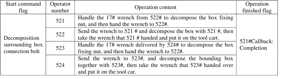
Using Unity3D as a development platform, the behavior modeling of the system is accomplished through scripting language. The implementation of the virtual operation is similar to the ordinary system development process. The first step is to determine the functions and operation specifications of different virtual operators according to the operational procedures of the equipment; the second step is to divide according to the established procedures and the functions of the operators. The preparation of the program, the format and content of the preparation are saved through the XML file format, so that the system can be updated later, the program writing and application steps can be reduced when the system is optimized, and the XML document can be updated in real time; The third step is to model the behavior of the system by calling the XML document on the Unity3D platform. The interception part of the operating rules of this system is shown in Table 1. The corresponding XML file program is written as:
<RatingsStep ID="4" Name="Resolve Enclosure Connection Bolt">
Name="#|Open End Wrench 1|#|Open End Wrench 3" StepAnimation="4_StepAnm_1" StepTips ="Hand the [#|1|#|3] from the tool cart [#|1|#|2] to the [#|1|#|3] trumpeter" BackTips="[#|1|# |3] Please answer the tool "StepDub="" />
<MemberStep ID="2" Number="1|#|3|#" StepDub="" ResultTips="Disassembled"" />
The ID number is given to the operator, a password is set at the beginning of the action, a flag is given at the end of a step. The "#" in the code identifies that the operator does not need to work, and other personnel work normally this action step. Through the modeling of the behavior of the operation procedure, the actual operation steps in the system are converted into virtual operations, and part of the system development is completed. The rest of the behavior modeling is carried out in accordance with the above steps, and finally complete the function implementation on the Unity3D platform.
Table 1. Operating procedures.
Start command flag
Operator
number Operation content
Operation finished flag
Decomposition surrounding box connection bolt
521 Handle the 17# wrench from 522# to decompose the box fixing nut, and then hand the wrench to 522#.
521#Callback: Completion 522 Send the wrench to 521 # and decompose the box with 521 #, then
take the wrench that 521 # handed and put it on the tool cart.
523 Handle the 17# wrench delivered by 524# to decompose the box fixing nut, and then hand the wrench to 522#.
524
Send the wrench to 523#, and decompose the bounding box together with 523#, then take the wrench that 523# handed over and put it on the tool car.
Collision Detection
The system involves a large number of model structure diagrams, and the model's structure is more complex, so in the process of equipment virtualization operations, there will inevitably be a large number of collision detection tests. Therefore, in order to improve the accuracy of collision detection and the good experience of the system, first divide the size of the model according to the size of the actual model, and divide the parts and tools whose length, width and height are more than 50cm into large models, and the other models are divided into Small model. Based on the model classification, the system provides two solutions for rigid body collision detection.
The first solution is to avoid the collision between rigid bodies by the fixed design of the behavior path of large models through complex operation behavior. The specific implementation scheme is to simplify the complex operation specification, then carry out 3Dsmax animation design, and determine the specific path of the operation step through animation design. The 3Dsmax animation can then be called in the appropriate place in the Unity3D script. When the operator triggers this instruction, the animation is called and the operation steps are displayed. Some of the calling programs and functions are as follows:
public const sring ANIM_NAME201 = "2_StepAnm_1"; if( Input.GetKeyDown(KeyCode.A))
{ anm[ANIM_NAME201].speed=1; anm.Play(ANIM_NAME201);}
distances of two objects are similar, it is detected whether there is an intersecting area in the first layer of bounding spheres. In this case, rough detection is used. If there is no intersecting area, there must be no intersecting collision. Specifically, assume that the center of the bounding sphere is (a, b, c) and the radius of the sphere is R, where X min, X max, Y min, Y max, Z min, and Z max represent the minimum of the object on the X, Y, and Z axes, respectively. With the projection and the maximum projection value, you can find the coordinate formula of the bounding sphere:
(
, ,) (
{ , ,)
|(
)
,(
)
,(
)
}O a b c = a b c a= X min+X max b= Ymin+Ymax c= Zmin+Zmax (1)
2 2 2
1
= ( max min) ( max min)
2 max min)
R (X −X + Y −Y + Z −Z
(2)
The area encompassed by the sphere is:
2 2 2 2
I={(x,y,z)T | (x−a) +(y−b) +(z−c) <R }
(3)
Assume that there are two model bounding spheres in three-dimensional space: (O1, R1), (O2, R2). You need to compare the distance d between the two centers and the size of (R1+R2). If d<(R1+R2), the two bounding spheres intersect; otherwise, they do not intersect.
After the first layer of rough detection, deep collision detection is performed on the model contained in the intersected area. Firstly, the second layer and the second layer are also surrounded by the ball intersection test. If they intersect, the second layer and the third are continued. The layer performs the OBB bounding box intersection test, and the third and third layers perform the intersection test between the OBB bounding boxes. The area of the OBB bounding box is determined as: Assuming that the center of the OBB bounding box is O, the direction of the bounding box cuboid is v1, v2, and v3, and the radius in the three directions is r1, r2, and r3, and it is possible to draw the OBB envelope. The area of the box is:
(
)
1 1 2 2 3 3 , , 1,
{ | 1 }
I= O+ar v +br v +cr v a b c∈ −
(4)
The three-layer structure hybrid level bounding box collision detection algorithm improves the detection accuracy and also avoids a large amount of redundant data update processing. At the same time, the system combines this algorithm with the first fixed path animation calling scheme, which greatly improves the accuracy of collision detection and improves the collision detection design of the model in the system.
Figure 4. Three-layer structure hybrid hierarchical bounding box structure.
System Optimization
basic purpose of this article, but the experience of human-computer interaction is too bad to be satisfied. The user needs better experience in use. To this end, the system is based on the writing of Unity3D's own scripts, and the use of Flash gives the release system a better visual experience and experience. The main system optimizations are:
The first is the redevelopment of embedded user interfaces. Flash Catalyst is a design tool that quickly creates expressive interfaces and interactive content without writing code. Through the use of the Flash Catalyst tool, a more functional interactive interface is created, and the system created by Unity3D is embedded in the Flash completed interface. By using the mouse pointer to trigger the option of the Flash interface, Unity3D content can be used. In this system, all the components are classified and classified in the structure recognition module. The component parts are assembled in the Flash interface and the parts assembly tree is constructed. Through the assembly tree, the details of the corresponding components can be selected and used by the user. The process has a deeper understanding of the structure of the equipment and ensures a good experience of the system.
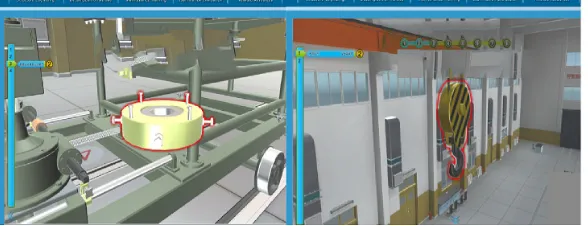
[image:6.612.161.455.445.558.2]The second is the optimization of feature functions. Written in C# language, you can understand the process of disassembly and reassembly process and the general operation of this step in real time. At the same time set the "Guide" option as a feature of the system. Due to the large number of components and the complicated structure of the equipment, it will be difficult to directly use this system for disassembly and reinstalling. At this time, you can turn on the “Guide” option. At this time, the system prompts you for this step. It is a combination of language prompts and color highlighting. It displays the operation conditions required by this step through the screen and gives the red-graded prompt color of the parts to be operated. Users can avoid frequent mistakes in the early stage of use. At the same time, they can use the "Guide" function to perform disassembly and reinstalling to ensure good system availability. As shown in Figure 5.The debugging of this system was carried out in the VS2015 version. One improvement of VS2015 is that it can directly debug the Unity program. After the final completion, the system is released on the Build interface, a visual simulation system for the equipment is generated, and the generated system is embedded in the interactive interface completed by the Flash. This completes the development of a virtual training system for equipment. Figure 5 shows the man-machine interaction scenario of a certain operation step.
Figure 5. Human-computer interaction.
Conclusion
References
[1]Fei Luan. Development of virtual simulation teaching system for hydraulic transmission based on Unity3D. Jinan: Shandong University of Architecture, 2015:11-14.
[2]Jun-feng Chen. Research and implementation of cross-platform mobile online games based on Unity3D. Guangzhou: Sun Yat-Sen University, 2013:9-11.
[3]Yi Zhang. Research and application of visual simulation technology based on HLA and Unity3D. Xi'an: Xidian University, 2014:19-24.
[4]Yi-bin Yang, Min Li, Hong-wen Xie. Desktop Virtual Maintenance Training System Based on Unity3D. Computer Applications, 2016, 36(S2).