2018 2nd International Conference on Applied Mathematics, Modeling and Simulation (AMMS 2018) ISBN: 978-1-60595-580-3
Chaotic Motions for a Class of the Compound Pendulum System
Peng JI
1, Liang-qiang ZHOU
1,*and Ling-hui LI
2 1College of Science, Nanjing University of Aeronautics and Astronautics, Nanjing 211100, China
2
College of Science, Hangzhou Normal University, Hangzhou 311121, China
Keywords: Compound pendulum, Melnikov method, Homoclinic orbit, Smale horseshoe.
Abstract: The dynamics equation of the compound pendulum system is studied with the Melnikov method. The critical condition of the chaotic motion is discussed and the critical curve of the parameter is drawn. With the Runge-Kutta method, Numerical simulations are given, which verified the analytical results. It is concluded that there exists Smale horseshoe chaos arising from transversal intersections of stable and unstable manifold of the homoclinic orbit. The critical values for chaos first increase and then decrease with the increasing of the driving torque.
Introduction
The compound pendulum system has a wide application prospect in many fields, such as architecture, space, military, medical, agriculture and so on. Therefore, it is of great practical significance to study the dynamic behavior of the compound pendulum. The concept of chaos proposed in nonlinear dynamics has been extensively studied in many fields[1] such as mathematics, physics, biology, engineering, chemistry and so on. In practical work, considering the driving torque and the actual damping torque, the compound pendulum motion presents nonlinear dynamic characteristics and may produce the motion state of bifurcation and chaos. Now, the research on compound pendulum system is mainly used in crusher[2-4], power generating turbine[5], air floatation platform[6], bionic mechanical[7].
In this paper, the chaotic motion of a kind of complex pendulum system is studied. The critical condition of its chaotic motion is discussed and the critical curve of the parameter is drawn. With the Runge-Kutta method, the system is simulated and the phase diagram of the system is drawn, which confirm the analytical results.
Mathematical Model
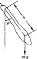
[image:1.595.276.343.588.692.2]The model of the compound pendulum device is shown in Figure 1. The compound pendulum is a dynamic system, in which a rigid body swings around a fixed horizontal axis with the action of gravity and it is also called a physical pendulum.
Figure 1. Compound pendulum.
The mathematical model for the compound pendulum:
sin cos
Wheremrepresents quality,I represents the moment of inertia for the rotating shaftO,h
represents the distance between the center of mass and the axis of the rotating shaft,k represents the damping torque in motion, pcostrepresents the driving torque, mghsinrepresents the heavy torque at any other angular displacement.
Chaotic Motion for the System
Considering the vibration at any angle, sinis expanded into 1 3
sin
6
, While the first
two items are taken, the gravitational moment can be expressed: ( 1 3) 6
M mgh
When ak I b/ , mgh I c/ , mgh/ 6 ,I dp I/ which are parameters related to damping, natural frequencies, nonlinearity and driving torque, the mathematical model can be transformed into[8]:
3
cos
a b c d t
(2) System (2)can be transformed into a state equation:
1 2
3
2 1 1
2
cos
a b c d t
(3)
Considering the situation of damping torque and weak driving torque, the system (3) is converted to
'
1 2
3
2 1 1 2
( ) 0
( ) cos
t
t b c a d t
(4)
where aa d, d,0 1.
When b 6,c1, 0,the undisturbed system is
1 2
3
2 1 1
( )
( ) 6
t t (5)
The system (5) is a Hamilton system[9], whose Hamilton quantity is
4 2 2
1 2 1 1 2
1 1
( , ) 3
4 2
H h
The equilibrium point of the system is O(0, 0), ( 6, 0), (A B 6, 0).Ois addle point andA B, are Center points.
2
0 0
2 2
2
2
( ) ( ( )) ( ( ), )
( )( ( ) cos ( ))
( ) ( ) cos ( )
4
12 sech( ) sin
3 2
M f q t g q t t
t a t d t dt
a t dt d t t dt
a d
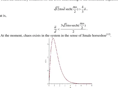
Thus, the necessary condition for the cross intersecting of the homoclinic trajectories is:
4
12 sech( )
2 3
d a
,
that is,
3 3 sech( )
2 2
a d
.
[image:3.595.67.466.188.495.2]At the moment, chaos exists in the system in the sense of Smale horseshoe[12].
Figure 2. The critical curve of chaotic motion for system (5).
As shown in Figure 2, when the parameter is located below the curve, the system generates chaotic motion. With the increase of driving torque, the chaotic threshold increases first and then decreases.
Numerical Simulation
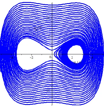
Numerical results of system (5) are obtained with Runge-Kutta method in the flowing. When
0.01,d 6,a 3, 1
, the phase diagram of the system (5) is shown in Figure 3.
Figure 3. The phase diagram of the system (5).
Conclusion
In this paper, the chaotic motion of a kind of complex pendulum system is mainly studied. The stable manifold of the homoclinic orbit and the cross section of the unstable manifold are the mechanism of the chaotic motion of the system. The critical and parameter critical curves of the chaotic motion of the system are discussed and given. With Runge-Kutta method, the phase diagram is obtained, and the results of theoretical analysis are verified.
Acknowledgement
This work is supported by by National Natural Science Foundation of China (11772148, 11572148), China Postdoctoral Science Foundation (2013T60531), and the Fundamental Research Funds for the Central Universities (NS2017046).
References
[1] H.P. Ren, D. Liu, H. Li, Delay feedback control of chaos in permanent magnet synchronous motor, Proceedings of the CSEE, 2003, 23(6) 175-176.
[2] K. Zhang, J.N. Liu, M.C. Yang, Motion Simulation and FEM Analysis of Compound Pendul Jaw Crusher, Coal Mine Machinery, 2008, 29(10) 69-71.
[3] H.P. Luo, Study on the effective space in the crushing cavity of the compound pendulum jaw crusher. Mining & Processing Equipment, 2010(5) 73-77.
[4] Z.Y. Qin, X.F. Rong, X.M. Xu, Design and optimization of crushing cavity for compound pendulum jaw crusher, Mining & Processing Equipment, 1992(2) 28-34.
[9] G. Barles, Viscosity solutions of Hamilton-Jacobi equations, Transactions of the American Mathematical Society, 1982, 61(1) 117-125.
[10] W. Omana, M Willem. Homoclinic orbits for a class of Hamiltonian systems. Proceedings of the Royal Society of Edinburgh, 1992, 114 (1-2) 33-38.
[11] P.J. Holmes, Melnikov's method and Arnold diffusion for perturbations of integrable Hamiltonian systems, Journal of Mathematical Physics, 1982, 23(4) 669-675.