An Experimental Study on Effect of Twisted Tape on Performance of
Plane Steel Tube and 550 Corrugated Steel Tube Double Pipe Heat
Exchanger
Shatrudhan Lal Kushwaha
1Mr. Sanjay Kumar Singh
21
M.Tech Student
2Associate Professor
1,2
Department of Mechanical Engineering
1,2
Sagar Institute of Science and Technology, Bhopal India
Abstract—The main aim of this comparative analysis is to determine effectiveness, over all heat transfer coefficient and number of transfer unit(NTU) using a straight steel tube double pipe heat exchanger(DPHE) with respect to 550
corrugated steel be DPHE without anything insert and 550
corrugated steel be DPHE with insert twisted tape half and full length. In current work the fluid to fluid heat exchange is taken into consideration, Most of the investigations on heat transfer coefficients are for constant wall temperature or constant heat flux. The effectiveness, overall heat transfer coefficient, effect of hot water flow rate on effectiveness of heat exchanger when cold water mass flow rate is kept constant. Here studied and compared for parallel flow and counter flow DPHE arrangement of Straight steel tube and 550 corrugated steel be DPHE without anything insert and
550 corrugated steel be DPHE with insert twisted tape half
and full length. All readings were taken at steady state condition of heat exchanger. The result shows in the graphical representation for effectiveness, LMTD, NTU and over all heat transfer coefficient for parallel flow and counter flow arrangement. Effectiveness of heat exchanger is decreases when mass flow rate of hot fluid is below 45LPH and then increases in straight steel and to 550
corrugated steel be DPHE without anything insert and 550
corrugated steel be DPHE with insert twisted tape half and full length when hot water mass flow rate varies and cold water flow is fixed at 45LPH
Key words: Effectiveness, LMTD, NTU and over All Heat Transfer Coefficient
I. INTRODUCTION
A heat exchanger is equipment which transfers the heat energy from hot fluid to a cold fluid without direct contact of the fluids as a result of temperature gradient take place. The design procedure of heat exchangers is quite complicated, as it needs exact analysis of heat transfer rate, efficiency and pressure drop apart from issues such as long term performance and the economic aspect of the equipment. The steel tube heat exchanger with inside 550
corrugated Double pipe heat exchanger (DPHE) is a modified form of simple steel tube DPHE. This modification increase some thermal efficiency as compare to simple DPHE. This kind of heat exchanger is widely used in chemical, food, oil and gas industries.
Heat transfer enhancement methods:- In general, heat transfer enhancement
methods are of following three main categories:
1) Active method:- This method involves some external power input for the enhancement of heat transfer. Some examples of active methods include induced pulsation by cams and reciprocating plungers.
2) Passive method:- This method generally uses surface or geometrical modifications to the flow channel by incorporating inserts or additional devices. For example, inserts extra component, swirl flow devices, treated surface, rough surfaces, extended surfaces, displaced enhancement devices, coiled tubes, surface tension devices and additives for fluids
3) Compound method:- Combination of the above two methods, such a rough surface with a twisted tape swirl flow device, or rough surface with fluid vibration, rough surface with twisted tapes.
It is focused on reviewing the passive methods in double pipe heat exchanger(DPHE).
II. PARAMETERS DEPENDS ON THE HEAT TRANSFER
A. Overall heat transfer [U]:
The overall heat transfer coefficient is a measure of the overall ability of a series of conductive and convective barriers to transfer heat. Overall heat transfer coefficient is the ratio of the heat transfer LMTD at unit area.
q=UAdt
q= heat transfer rate (W)
U= overall heat transfer rate (W/ (m2.K))
A = heat transfer surface area (m2)
dt= LMTD (K)
B. Effectiveness [€] :- The effectiveness (€), is the ratio between the actual heat
transfer rate and the maximum heat transfer rate: €=qact/qmax
€= effectiveness
qact= actual heat transfer rate (W) qmax = maximum heat transfer rate (W)
C. LMTD (logarithmic mean temperature difference) : We assumed that a generic heat exchanger has two ends (which we called A and B) at which the hot and cold streams enters or exit on either sides then the LMTD is defined by the logarithmic mean as follows
LMTD = ΔTA− ΔTB ln(ΔTA/ΔTB) Where,
Δ𝑇𝐴 = temperature difference between two streams at A And ΔTB = temperature difference between two streams at B .
D. NTU (number of transfer unit)
NTU method is used:
NTU= UA/Cmin
Where,
U = overall heat transfer coefficient A= heat transfer area
Cmin= minimum capacity of thermal energy.
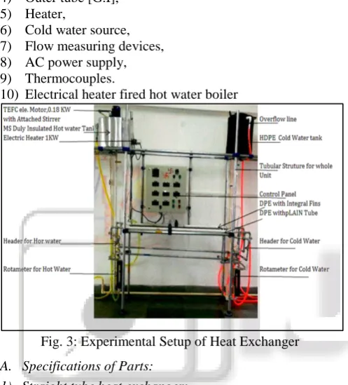
III. EXPERIMENTAL SETUP
The set-up consisted of the following components: 1) Plain Steel Tube,
2) 550 corrugated Steel Tube
3) Twisted Inserts 4) Outer tube [G.I], 5) Heater,
6) Cold water source, 7) Flow measuring devices, 8) AC power supply, 9) Thermocouples.
[image:2.595.307.554.53.195.2]10) Electrical heater fired hot water boiler
Fig. 3: Experimental Setup of Heat Exchanger
A. Specifications of Parts: 1) Straight tube heat exchanger:
Plain Steel tube heat exchanger consists of 10 mm inner and length 1.5meter plain tube. The hot water flow rate was measured and controlled with rotameter; similarly cold water through second rotameter enters at top of one side of outer tube and exit from top of other side of outer tube.
Fig. 3.1.1: Double Pipe heat Exchanger (DPHE) Straight steel Tube
2) Hot Water Tank:
[image:2.595.45.294.204.479.2]Hot water tank is installed on the CI pipe steel frame on the left top corner. It is the source of hot water using electric heater for heat exchanger. Hot water tank is shown in figure.
Fig. 3.1.2: Hot Water Tank 3) Control Panel:
The control panel consist all circuit of the system, the various parameter of heater, motor and temperature indicator depend on it. It helps in smooth operation of electrical equipment.
Fig. 3.1.3: Control Panel and Display Board 4) Motor and Stirrer
[image:2.595.308.554.258.429.2]Motor and Stirrer are used to produced swirl in the hot water which is kept in the hot water tank. This motor and stirrer arrangement is installed inside
Fig. 3.1.4: Motor & Stirrer TEFC Weather proof Electric
Motor
Power 3P 440V 50Hz RPM 1400
KW 0.18 Frame 63
[image:2.595.377.481.462.665.2] [image:2.595.46.292.546.664.2]5) Boiler: Make of item.
1) Plate : - is 2062 m.s. plate 2) Tube : - tata / ti/ msl
3) Valve : - sant / atam /mahavir. 4) Pump : - standred
5) Pr. switch : - indfos/ standred 6) Contecters : - seimens/ l& t 7) Panel : - powder coated dust proof 8) Relay : - seimens/l&t
9) Pre. gauge : - arihant 10) Heater : - s.b.s
11) Safety valve : - sant / atam / mahavir 12) Ele. motor : - abb / crompton. a) Specification:-
[image:3.595.27.544.50.734.2]1) Hot water Boiler: It is a 100L water capacity vertical cylindrical shaped boiler which consist a heater of capacity 9KW at bottom end, it also have inlet point for cold fluid and suction point for water pump, air vent at top side, blow down valve at bottom side, water level tube, float switch for heater safety, thermocouple for inside temp. Measurement, Top side man hole for boilers cleaning. Out of 100L capacity.
Fig. 3.1.5: Design and fabrication of boiler
2) Water circulation pump: One of hot water shifting pump supply with motor fitting in same base frame. its power consumption is just 0.5 HP and deliver hot water upto height of 6-24 m.
3) Heater Systems: one no. of immersion flanged type best quality heater. It has 9KW power by this we can get hot water of 60º-90ºC temp. In just 25-35 minute we save our valuable time.
6) Specifications of plain tube heat exchanger :
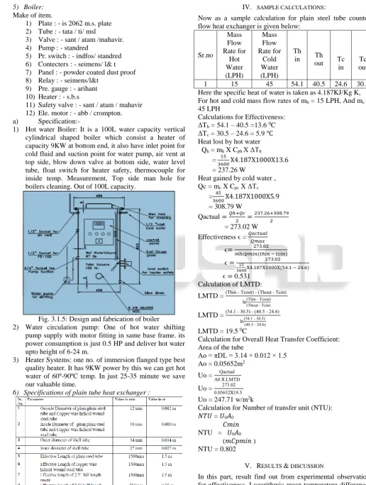
IV. SAMPLE CALCULATIONS:
Now as a sample calculation for plain steel tube counter flow heat exchanger is given below:
Sr.no
Mass Flow Rate for
Hot Water (LPH)
Mass Flow Rate for
Cold Water (LPH)
Th
in Th
out Tc
in Tc out
1 15 45 54.1 40.5 24.6 30.5
Here the specific heat of water is taken as 4.187KJ/Kg K, For hot and cold mass flow rates of mh = 15 LPH, And mc =
45 LPH
Calculations for Effectiveness: ΔTh = 54.1 – 40.5 =13.6 0C
ΔTc = 30.5 – 24.6 = 5.9 ℃
Heat lost by hot water Qh = mh X Cph X ΔTh
= 15
3600X4.187X1000X13.6
= 237.26 W
Heat gained by cold water , Qc = mc X Cpc X ΔTc
= 45
3600X4.187X1000X5.9
= 308.79 W
Qactual =𝑄ℎ+𝑄𝑐
2 =
237.26+308.79 2 = 273.02 W
Effectiveness ϵ = 𝑄𝑎𝑐𝑡𝑢𝑎𝑙 𝑄𝑚𝑎𝑥
ϵ= 273.02 𝑚h𝑐𝑝𝑚𝑖𝑛(𝑡ℎ𝑖𝑛 − 𝑡𝑐𝑖𝑛)
ϵ = 15 273.02
3600X4.187X1000X(54.1 − 24.6) ϵ = 0.531
Calculation of LMTD:
LMTD = (Thin - Tcout) - (Thout - Tcin) ln(Thin - Tcout)
(Thout - Tcin)
LMTD = (54.1 - 30.5) - (40.5 - 24.6) ln(54.1 - 30.5) (40.5 - 24.6)
LMTD = 19.5 0C
Calculation for Overall Heat Transfer Coefficient: Area of the tube
Ao = πDL = 3.14 × 0.012 × 1.5 Ao = 0.05652m2
Uo = Qactual A0 X LMTD Uo = 273.02
0.05652X19.5 Uo = 247.71 w/m2k
Calculation for Number of transfer unit (NTU): 𝑁𝑇𝑈 = 𝑈0𝐴0
𝐶𝑚𝑖𝑛 NTU = 𝑈0𝐴0
(𝑚𝐶𝑝𝑚𝑖𝑛 ) NTU = 0.802
V. RESULTS & DISCUSSION
[image:3.595.299.558.87.178.2]Table: 5.1. Plane Steel Tube Heat Exchanger Without Insert When Cold Water is Fixed at 45 LPH In counter flow:-
Observation table
S.No. Vol. flow Rate of Hot Water (Mh) (LPH)
Vol. flow rate of Cold water (Mc) (LPH)
Thot(inlet)
(oC)
Thot
(Outlet) (oC)
Tcold(inlet)
(oC)
Tcold
(Outlet) (oC)
1. 15 45 54.1 40.5 24.6 30.5
2. 30 45 54.9 43.8 24.6 31.6
3. 45 45 55.5 45.8 24.6 32.8
4. 60 45 56 47.3 24.6 33.9
5. 75 45 56.4 48.6 24.6 35.3
Calculation table
S.No.
Vol. flow Rate of Hot Water (Mh)
(LPH)
Vol. flow rate of Cold water (Mc) (LPH)
Effectiveness (ϵ) Logarithmic mean Temperature Difference (LMTD)
Өm= (∆𝑇1−∆𝑇2)
ln(∆𝑇1∆𝑇2)
Overall heat Transfer Coefficient (U) Number Of Transfer unit (NTU) Heat gain by cold fluid (Qc)
1. 15 45 0.531 19.5 247.71 0.802 308.79
2. 30 45 0.356 21.18 305.71 0.496 366.36
3. 45 45 0.290 21.94 345.75 0.374 429.17
4. 60 45 0.333 22.4 384.13 0.415 486.74
5. 75 45 0.373 22.52 439.59 0.475 560.01
In parallel flow:- Observation table
S.No. Vol. flow Rate of Hot Water (Mh) (LPH)
Vol. flow rate of Cold water (Mc) (LPH)
Thot(inlet)
(oC)
Thot
(Outlet) (oC)
Tcold(inlet)
(oC)
Tcold
(Outlet) (oC)
1. 15 45 52.7 38.4 23.4 28.4
2. 30 45 53.3 41.8 23.4 29.5
3. 45 45 54.1 43.7 23.4 30.6
4. 60 45 55.1 45.6 23.4 31.7
5. 75 45 55.8 47 23.4 32.6
Calculation table
S.No.
Vol. flow Rate of Hot Water (Mh)
(LPH)
Vol. flow rate of Cold water (Mc) (LPH)
Effectiveness (ϵ) Logarithmic mean Temperature Difference (LMTD)
Өm= (∆𝑇1−∆𝑇2)
ln(∆𝑇1 ∆𝑇2) Overall heat Transfer Coefficient (U) Number Of Transfer unit (NTU) Heat gain by cold fluid (Qc)
1. 15 45 0.5 17.95 257.65 0.836 261.69
2. 30 45 0.345 19.81 284.82 0.462 319.26
3. 45 45 0.287 20.67 322.33 0.348 376.83
4. 60 45 0.331 21.59 355.65 0.384 434.4
5. 75 45 0.368 22.2 383.46 0.415 481.51
Table: 5.2. 55’ Corrugated Tube Heat Exchanger without Insert When Cold Water is Fixed at 45 LPH In counter flow:- Observation table
S.No. Vol. flow Rate of Hot Water (Mh) (LPH)
Vol. flow rate of Cold water (Mc) (LPH)
Thot(inlet)
(oC)
Thot
(Outlet) (oC)
Tcold(inlet)
(oC)
Tcold
(Outlet) (oC)
1. 15 45 53.7 40.3 24.4 30.7
2. 30 45 54.6 42.8 24.4 31.8
3. 45 45 55.4 44.6 24.4 33
4. 60 45 56 46.4 24.4 34.2
5. 75 45 56.3 47.5 24.4 35.3
Calculation table
S.No.
Vol. flow Rate of Hot Water (Mh)
(LPH)
Vol. flow rate of Cold water (Mc) (LPH)
Өm= (∆𝑇1−∆𝑇2) ln(∆𝑇1
∆𝑇2)
1. 15 45 0.551 19.23 303.06 0.983 329.73
2. 30 45 0.379 20.52 333.61 0.541 387.30
3. 45 45 0.313 21.28 373.87 0.404 450.1
4. 60 45 0.358 21.90 414 0.448 512.91
5. 75 45 0.401 22.98 457.68 0.495 570.48
In parallel flow: - Observation table
S.No. Vol. flow Rate of Hot Water (Mh) (LPH)
Vol. flow rate of Cold water (Mc) (LPH)
Thot(inlet)
(oC)
Thot
(Outlet) (oC)
Tcold(inlet)
(oC)
Tcold
(Outlet)(oC)
1. 15 45 52.3 38.7 23.3 28.7
2. 30 45 53.5 41.1 23.3 29.8
3. 45 45 54.3 43.4 23.3 31.0
4. 60 45 54.9 45.3 23.3 32.4
5. 75 45 55.5 46.4 23.3 33.5
Calculation table
S.No.
Vol. flow Rate of Hot Water (Mh)
(LPH)
Vol. flow rate of Cold water (Mc) (LPH)
Effectiveness (ϵ)
Logarithmic mean Temperature
Difference (LMTD)
Өm= (∆𝑇1−∆𝑇2)
ln(∆𝑇1∆𝑇2)
Overall heat Transfer Coefficient
(U)
Number Of Transfer unit
(NTU)
Heat gain by cold fluid (Qc)
1. 15 45 0.514 17.85 279.95 0.908 282.62
2. 30 45 0.367 19.23 312.78 0.507 340.19
3. 45 45 0.300 20.30 350.94 0.379 403
4. 60 45 0.347 20.87 403.36 0.436 476.27
5. 75 45 0.394 21.10 447.26 0.483 533.84
Table: 5.3. 55’ Corrugated Tube Heat Exchanger 2.5” full length Insert When Cold Water is Fixed at 45 LPH In counter flow:- Observation table
S.No. Vol. flow Rate of Hot Water (Mh) (LPH)
Vol. flow rate of Cold water (Mc) (LPH)
Thot(inlet)
(oC)
Thot
(Outlet) (oC)
Tcold(inlet)
(oC)
Tcold
(Outlet) (oC)
1. 15 45 54 37.8 24.5 31.9
2. 30 45 55.1 41.3 24.5 33.2
3. 45 45 55.8 43.6 24.5 34.3
4. 60 45 56.3 45.1 24.5 35.5
5. 75 45 56.8 47.3 24.5 36.9
Calculation table
S.S. No.
Vol. flow Rate of Hot Water (Mh)
(LPH)
Vol. flow rate of Cold water (Mc) (LPH)
Effectiveness (ϵ)
Logarithmic mean Temperature
Difference (LMTD)
Өm= (∆𝑇1−∆𝑇2)
ln(∆𝑇1 ∆𝑇2)
Overall heat Transfer Coefficient
(U)
Number Of Transfer unit
(NTU)
Heat gain by cold fluid (Qc)
1. 15 45 0.651 17.33 395.07 1.281 387.3
2. 30 45 0.439 19.24 418.4 0.678 455.34
3. 45 45 0.351 20.28 447.15 0.483 512.91
4. 60 45 0.408 20.70 491.63 0.531 575.71
5. 75 45 0.437 21.32 538.16 0.582 648.99
In parallel flow:- Observation table
S.No. Vol. flow Rate of Hot Water (Mh) (LPH)
Vol. flow rate of Cold water (Mc) (LPH)
Thot(inlet)
(oC)
Thot
(Outlet) (oC)
Tcold(inlet)
(oC)
Tcold
(Outlet) (oC)
1. 15 45 52.5 38.9 24.6 30.5
2. 30 45 53.4 40.8 24.6 31.8
3. 45 45 54.2 43.1 24.6 32.9
4. 60 45 54.9 45.6 24.6 34.2
5. 75 45 55.8 47.3 24.6 35.9
S.No.
Vol. flow Rate of Hot Water (Mh)
(LPH)
Vol. flow rate of Cold water (Mc) (LPH)
Effectiveness (ϵ) Logarithmic mean Temperature Difference (LMTD)
Өm= (∆𝑇1−∆𝑇2)
ln(∆𝑇1 ∆𝑇2) Overall heat Transfer Coefficient (U) Number Of Transfer unit (NTU) Heat gain by cold fluid (Qc)
1. 15 45 0.561 16.24 336.01 1.09 308.79
2. 30 45 0.406 17.02 391.31 0.635 376.83
3. 45 45 0.328 18.21 421.7 0.456 434.4
4. 60 45 0.363 19.33 459.36 0.497 502.44
5. 75 45 0.408 19.67 531.59 0.575 591.41
Table: 5.4. 55’ Corrugated tube 2.5” half-length Insert When Cold Water is Fixed at 45 LPH In counter flow: -
Observation table
S.No. Vol. flow Rate of Hot Water (Mh) (LPH)
Vol. flow rate of Cold water (Mc) (LPH)
Thot(inlet)
(oC)
Thot
(Outlet) (oC)
Tcold(inlet)
(oC)
Tcold
(Outlet) (oC)
1. 15 45 53.8 38.5 24 30.8
2. 30 45 54.7 41.7 24 32.1
3. 45 45 55.4 43.7 24 33.2
4. 60 45 56 45.4 24 34.4
5. 75 45 56.5 47.1 24 35.8
Calculation table
S.No.
Vol. flow Rate of Hot Water (Mh)
(LPH)
Vol. flow rate of Cold water (Mc) (LPH)
Effectiveness (ϵ) Logarithmic mean Temperature Difference (LMTD)
Өm= (∆𝑇1−∆𝑇2)
ln(∆𝑇1∆𝑇2)
Overall heat Transfer Coefficient (U) Number Of Transfer unit (NTU) Heat gain by cold fluid (Qc)
1. 15 45 0.599 18.42 341.45 1.107 355.9
2. 30 45 0.410 20.05 373.75 0.610 423.93
3. 45 45 0.333 20.93 406.76 0.440 481.51
4. 60 45 0.383 21.50 447.52 0.484 544.31
5. 75 45 0.423 21.88 498.99 0.539 617.58
In parallel flow:- Observation table
S.No. Vol. flow Rate of Hot Water (Mh) (LPH)
Vol. flow rate of Cold water (Mc) (LPH)
Thot(inlet)
(oC)
Thot
(Outlet) (oC)
Tcold(inlet)
(oC)
Tcold
(Outlet) (oC)
1. 15 45 52.6 38.5 24.1 29.7
2. 30 45 53.7 41.3 24.1 30.9
3. 45 45 54.7 43.8 24.1 32.1
4. 60 45 55.4 45.7 24.1 33.5
5. 75 45 55.8 47.1 24.1 34.9
Calculation table
S.No.
Vol. flow Rate of Hot Water (Mh)
(LPH)
Vol. flow rate of Cold water (Mc) (LPH)
Effectiveness (ϵ) Logarithmic mean Temperature Difference (LMTD)
Өm= (∆𝑇1−∆𝑇2)
ln(∆𝑇1 ∆𝑇2) Overall heat Transfer Coefficient (U) Number Of Transfer unit (NTU) Heat gain by cold fluid (Qc)
1. 15 45 0.542 16.76 309.05 1.002 293.09
2. 30 45 0.382 18.36 342.72 0.556 355.9
3. 45 45 0.309 19.66 376.49 0.407 418.7
4. 60 45 0.357 20.27 428.99 0.464 491.97
5. 75 45 0.399 20.42 489.28 0.529 565.25
Graph: 5.1. Comparative analysis of effectiveness when cold water is constant at 45 LPH for Plane steel tube, 55’ corrugated steel tube without inserts and 55’ corrugated
steel tube DPHE with 2.5” full & half length inserts in counter flow arrangement.
Graph: 5.2. Comparative analysis of effectiveness when cold water is constant at 45 LPH for Plane steel tube, 55’ corrugated steel tube without inserts and 55’ corrugated
steel tube DPHE with 2.5” full & half length inserts in parallel flow arrangement.
Graph: 5.3. Comparative analysis of LMTD when cold water is constant at 45 LPH for Plane steel tube, 55’ corrugated steel tube without inserts and 55’ corrugated
steel tube DPHE with 2.5” full & half length inserts in counter flow arrangement.
Graph: 5.4. Comparative analysis of LMTD when cold water is constant at 45 LPH for Plane steel tube, 55’ corrugated steel tube without inserts and 55’ corrugated
steel tube DPHE with 2.5” full & half length inserts in parallel flow arrangement.
Graph: 5.5. Comparative analysis of Overall heat transfer Coefficient when cold water is constant at 45 LPH for Plane
steel tube, 55’ corrugated steel tube without inserts and 55’ corrugated steel tube DPHE with 2.5” full & half length
inserts in counter flow arrangement.
Graph: 5.6. Comparative analysis of Overall heat transfer Coefficient when cold water is constant at 45 LPH for Plane
steel tube, 55’ corrugated steel tube without inserts and 55’ corrugated steel tube DPHE with 2.5” full & half length
Graph: 5.7. Comparative analysis of NTU when cold water is constant at 45 LPH for Plane steel tube, 55’ corrugated
steel tube without inserts and 55’ corrugated steel tube DPHE with 2.5” full & half length inserts in counter flow
arrangement.
Graph: 5.8. Comparative analysis of NTU when cold water is constant at 45 LPH for Plane steel tube, 55’ corrugated
steel tube without inserts and 55’ corrugated steel tube DPHE with 2.5” full & half length inserts in parallel flow
arrangement.
Graph: 5.9. Comparative analysis of heat transfer rate in cold fluid when cold water is constant at 45 LPH for Plane steel tube, 55’ corrugated steel tube without inserts and 55’ corrugated steel tube DPHE with 2.5” full & half length
inserts in counter flow arrangement
Graph: 5.10. Comparative analysis of heat transfer rate in cold fluid when cold water is constant at 45 LPH for Plane steel tube, 55’ corrugated steel tube without inserts and 55’ corrugated steel tube DPHE with 2.5” full & half length
inserts in parallel flow arrangement.
VII. CONCLUSION
In this experimental analysis of a straight steel tube and 550
Corrugated Steel Tube Double Pipe Heat Exchanger for parallel and counter flow in heat transfer lab with experimental setup. In experimental setup shell dimensions was also same. The mass flow rates inside tube and outside tube were varied as well as parallel flow and counter flow arrangement.
The effectiveness of heat exchanger significantly affected by cold water flow rate and hot water flow rate. When cold water mass flow rate is fixed at 45 LPH and increases mass flow rate of hot water then effectiveness is gradually decreases at mass flow rate of hot water is 45LPH then increases with increase mass flow rate of hot water. 550
Corrugated Steel Tube with 2.5” pitch full length is insert in steel tube is more effective in all condition when counter flow and parallel flow. The maximum value of heat transfer rate was found in counter flow arrangement with 2.5” full length insert.
The maximum value of effectiveness in counter flow arrangement in case of plane steel tube without insert, copper wire tube without insert and 2.5” half-length insert respectively.
It was observed that the value of overall heat transfer coefficient increases with increase in volume flow rate of hot fluid and maximum value of overall heat transfer coefficient was found in case of 2.5” full length insert was 538 W/m2K.
It was observed that the value of LMTD increases with increase in volume flow rate of hot fluid and maximum value of LMTD was observed in case of 550 corrugated steel
tube without insert was 22.98 0c. and it was 10.8%, 8.2%
and 13% greater than the value found in 2.5” half-length insert, 550 corrugated steel tube without insert and 2.5” full
length insert respectively.
REFERENCES
[1] D.D Clarke, V.R Vasquez,W.B
of heat exchanger Designs to physical properties estimation,Applied thermal Engineering 21 (2001) 993-1017.
[2] S. Rozzi, R. Massini, G. Paciello, G. Pagliarini, S.Rainieri, A. Trifiro, Heat treatment of fluid foods in a shell and tube heat exchanger: comparison between smooth and helically corrugated wall tubes, J. Food Eng. 79 (2007) 249–254.
[3] Carsten Schroer , Olaf Wedemeyer, Josef Novotny, Aleksandr Skrypnik, Jürgen Konys, Long-term service of austenitic steel 1.4571 as a container material for flowing lead–bismuth eutectic, Journal of Nuclear Materials 418 (2011) 8–15.
[4] Zaid S. Kareem,M.N. Mohd Jaafar, Tholudin M. Lazim, Shahrir Abdullah , Ammar F. Abdulwahid (2015) heat transfer enhancement review in corrugation. Experimental Thermal and Fluid Science 68 (2015) 22– 38.
[5] M. Mazaheri a, F. Djavanroodi a,, K.M. Nikbin, Creep life assessment of an overheated 9Cr-1Mo steel tube, International Journal of Pressure Vessels and Piping 87 (2010) 746e752.
[6] Navid Parnian, Failure analysis of austenitic stainless steel tubes in a gas fired steam heater, Materials and Design 36 (2012) 788–795.
[7] P.V. Durga Prasad1, A.V.S.S.K.S. Gupta2 and K. Deepak, Investigation of Trapezoidal- Cut Twisted Tape Insert in a Double Pipe U-Tube Heat Exchanger using Al2O3/Water Nanofluid, Procedia Materials Science 10 ( 2015 ) 50 – 63.
[8] Rad, Sepideh Esmaeili, et al. “Heat Transfer Enhancement in Shell-and-Tube Heat Exchangers Using Porous Media.” Heat Transfer Engineering, vol.
36, no. 3, 2014, pp. 262–277.,
doi:10.1080/01457632.2014.916155
[9] Zan Wu, Lei Wang, Bengt Sundén, Pressure drop and convective heat transfer of water and nanofluids in a double-pipe helical heat exchanger, Applied Thermal Engineering 60 (2013) 266e274.
[10]F. Taib Heakala, M.M. Hefnya, A.M. Abd El-Tawabb, Electrochemical behavior of 304L stainless steel in high saline and sulphate solutions containing alga Dunaliella Salina and_-carotene, Journal of Alloys and Compounds 491 (2010) 636–642.