item and our policy information available from the repository home page for further information.
Author(s):Sooriyakumar, G., Perryman, Roy; Dodds, Stephen J.
Title: Improved cogging calculation methods for surface mounted permanent magnet synchronous motors
Year of publication:2007
Citation: Sooriyakumar, G., Perryman, R., Dodds, S. J. (2007) ‘Improved cogging calculation methods for surface mounted permanent magnet synchronous motors’ Proceedings of Advances in Computing and Technology, (AC&T) The School of Computing and Technology 2nd Annual Conference, University of East London, pp.222-227
Link to published version:
IMPROVED COGGING CALCULATION METHODS FOR
SURFACE MOUNTED PERMANENT MAGNET
SYNCHRONOUS MOTORS
*G. Sooriyakumar, R. Perryman, S. J. Dodds
*
Control Techniques Dynamics Ltd, Andover, Hants, UK
Control Research Group, SCoT, UEL {r.perryman, s.j.dodds}@uel.ac.uk
Abstract: As part of the design process of surface mounted permanent magnet synchronous motors (PMSM), a combination of analytical calculation and finite element analysis (FEA) is proposed for the cogging torque calculation. The analytical methods are recommended for the initial design iterations in view of their high computational speed. In general, however, finite element analysis is more accurate and is therefore recommended for the final design iterations. In order to obtain continuity when switching from analytical calculations to FEA, two modifications are made to the equations upon which the analytical methods are based in order to improve accuracy. This is demonstrated by comparing the results from the unmodified and modified analytical method with those using the finite element method through their application using the nominal parameters of a Control Techniques Dynamics CTD 142UMC300 motor. Air-gap flux density calculations are compared as well as cogging torque calculations.
1 Introduction
Cogging torque is an unwanted but unavoidable characteristic in permanent magnet synchronous motors. Consequently, it is usual to design a PMSM with a cogging torque less than 1.5% of the stall torque. To carry out the necessary calculations, analytical and finite element methods are available. In general, the finite element methods are more precise than the analytical methods but are more time consuming. In order for the design engineer to minimise the computational time without compromising accuracy, it is proposed to use an analytical method to arrive at a rough design through some iterations using design parameters such as the permanent
magnet dimensions, followed by fine tuning with finite element analysis.
knowledge that a finite element package is capable of more accurate results, the analytical calculation is verified by means of finite element analysis.
The intention is not to improve the analytical method to the extent of replacing the finite element method but to improve it to a level where it is able to help the motor designer achieve a good ‘first cut’ design prior to use of the finite element method for refinement. It should be noted, however, that computational errors become more significant (as a percentage of the peak cogging torque) as the design is improved to reduce the peak cogging torque. Although the calculation can be improved by better geometry and mesh creation, this will not eliminate the problem entirely. There are two main methods upon which finite element programmes are based. The first is the Maxwell stress method and the second is the energy method. The Maxwell stress method is the most common and its accuracy depends on the contour location as well as the judiciously chosen mesh sizing. The energy method does not have contour dependent accuracy but suffers from the drawback of numerical differentiation and the associated errors. In this paper, the Maxwell stress method is employed.
2. Standard Formulae for
Analytical Methods
The well known cogging torque formulae of Zhu and Howe is in common use [1] [2] [3] and is used in this study. It is formulated in three stages. First, the air gap flux density distribution formula for the ideal slot-less machine is taken. Then it is modified to take account of the air gap permeance. Finally the cogging torque is calculated from modified air gap flux
density. Thus, the equation for the flux density at the surface of the stator bore of an ideal slot-less machine is as follows:
1 0
2 1 3 5
1 2
2
2 2
2
1
1 2 1
1 1 1 + ∞ = + = − − + − + + − − − −
∑
rl np n mn , , ,.... r s
np np r r m m np r r r s np np m r r
r s m
B ( )
M np R
R ( np )
R R
( np ) ( np )
R R . R R R R R R θ µ µ µ µ µ µ ( )
cos npθ
(1) where 0 2 2 2 = p r n p p n sin B M n πα α
µ πα , Br is
the remanence flux density of the magnet,
0
µ is the permeability of free space, Rm is
the magnet outer radius of curvature, Rs is
the stator bore radius, Rr is the rotor radius, p is the number of pole pairs and
r
µ is the relative permeability of the magnetic stator and rotor material.
Then the slotting effect is taken into account by means of the permeance equation 1 2 + = + + m r rel m r l g l g w µ λ π µ (2)
2 2
1 1 1
0 1
2 1 0
2 2 2
2
2 =
+
=
− +
∫
∑
∫
s
ws
N PM s
ws cog
m
PM s
ws
B ( w ).( R w )dw L
T ( )
B ( w ).( R w )dw θ
µ (3)
and computed by means of the equivalent discrete algorithm obtained by numerical approximations to the integrals:
(
)
2
1 1
1 0
2
2 =
= + +
∑
Ns
cog PM M
m
LR
T ( ) B m . R g .ssg
N N α
π π
θ θ
µ (4)
where
{
{
12
0 and 0 outside the slot opening on the left side and 1 of the slot opening
on the right side and 1 of the slot opening
= =
= + =
= + = −
g ssg
g w g ssg
g w g ssg
α
α
α
.
(5)
3. Modified
Formulae
3.1 Tapered Magnet Profile
A common measure taken to reduce cogging torque is decreasing the radius of curvature of the outer surface of the permanent magnet to obtain an increase of the air gap towards the edges of the magnet so as to achieve a closer approximation to the ideal sinusoidal flux distribution around the air gap [3] [4] [5]. This yields a tapered magnet profile as illustrated in Figure 1. Here, the centre of curvature of the magnet outer surface is offset by Moff from the rotor centre and
increase of this parameter yields increase of the tapering.
The standard cogging formulae presented in section 2 becomes inaccurate once
magnet tapering is introduced. To overcome this problem, the following formula for Rm has been implemented,
[image:4.595.301.515.103.469.2]based on the geometry of Figure 1.
Figure 1 Geometry of tapered magnet profile
1
−
+
=
off out
out m
M sin( )
M sin sin M
R
sin( ) θ θ
θ (6)
3.2 Bread-loaf Magnet Profile
An alternative method to the magnet tapering for cogging torque reduction is to maintain coincidence of the centre of curvature of the outer magnet surface and the rotor centre to keep a constant air gap but introduce a flat inner magnet surface, as illustrated in Figure 2.
for Rr according to the geometry of Figure 2:
2 2
4
− =
wid in r
M M
[image:5.595.81.302.155.407.2]R cos( )θ (7)
Figure 2 Geometry of bread-loaf magnet profile
4. Computational
Results
A C++ program was developed for the analytical method based on equations (1), (2) and (4) for the non tapered magnet design and additionally equation (6) for the magnet tapering by variation of the outer magnet radius of curvature and equation (7) for the bread-loaf magnet.
For the finite element calculation, Opera 2d was employed. The Maxwell integration is performed along a circular contour going through the air gap. The integration is undertaken near to the rotor and near to the stator and then the average is taken.
In all cases, the air gap flux density and the corresponding cogging torque is plotted against rotor angle in degrees, two plots being displayed, one for the analytical
method and the other for the finite element method.
4.1 Standard Formulae
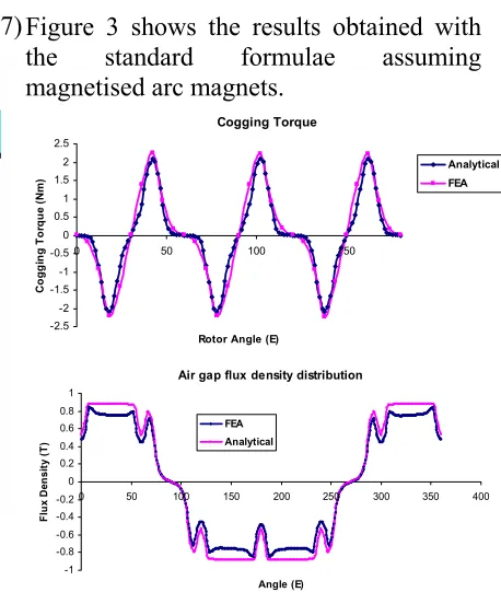
Figure 3 shows the results obtained with the standard formulae assuming magnetised arc magnets.
Cogging Torque
-2.5 -2 -1.5 -1 -0.5 0 0.5 1 1.5 2 2.5
0 50 100 150
Rotor Angle (E)
C
o
g
g
ing Tor
q
u
e
(N
m
)
Analytical FEA
Air gap flux density distribution
-1 -0.8 -0.6 -0.4 -0.2 0 0.2 0.4 0.6 0.8 1
0 50 100 150 200 250 300 350 400
Angle (E)
F
lux
D
ens
it
y
(T)
[image:5.595.296.525.172.448.2]FEA Analytical
Figure 3, Comparison of Finite Element and analytical results for non-tapered magnet
Although the errors between the analytical and FEA plots are significant, they are not so large that they would entail an excessive number of design iterations with the FEA after the initial iterations using the analytical method in order to arrive at an optimal design. Hence, if similar levels of errors between the analytical and FEA plots are obtained for the modified formulae in the following two sections, then the results will be considered satisfactory.
4.2 Modified Formulae for Tapered Magnet Profile
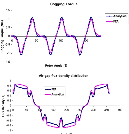
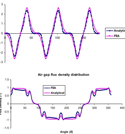
modified to cater for the tapered magnet profile. As expected, the peak cogging torque is reduced compared to non tapered case of Figure 3. Comparing Figures 4 and 5 shows that increasing the offset, Moff
significantly reduces the peak cogging torque.
In Figures 4 and 5, the percentage errors between the analytical and FEA plots are of a similar order to those obtained in Figure 3. The modified formula for the tapered magnet profile therefore produces satisfactory results.
It must be noted, however, that a severe taper reduces the magnet thickness so much at its ends that it will adversely affect the demagnetisation characteristics of the motor.
Cogging Torque
-2 -1.5 -1 -0.5 0 0.5 1 1.5 2
0 50 100 150
Rotor Angle (E)
C
o
gg
in
g
To
rq
ue
(
N
m
)
Analytical FEA
Air gap flux density distribution
-1 -0.8 -0.6 -0.4 -0.2 0 0.2 0.4 0.6 0.8 1
0 50 100 150 200 250 300 350 400
Angle (E)
Fl
ux
De
ns
it
y
(T
)
[image:6.595.311.532.111.340.2]FEA Analytical
Figure 4. Comparison of Finite Element and analytical results for taper with Moff = 3.35mm
Cogging Torque
-1.5 -1 -0.5 0 0.5 1 1.5
0 50 100 150
Rotor Angle (E)
C
ogg
ing Tor
que
(
N
m
)
Analytical FEA
Air gap flux density distribution
-1 -0.8 -0.6 -0.4 -0.2 0 0.2 0.4 0.6 0.8 1
0 50 100 150 200 250 300 350 400
Angle (E)
Fl
ux
D
ens
it
y (T)
FEA Analytical
Figure 4 Comparison of Finite Element and analytical results for taper with Moff = 6.35mm
4.3 Modified Formulae for
Bread-loaf Magnet Cogging Torque Profile
[image:6.595.85.294.383.635.2]-3 -2 -1 0 1 2 3
0 50 100 150
Analytical FEA
Air gap flux density distribution
-1.5 -1 -0.5 0 0.5 1 1.5
0 50 100 150 200 250 300 350 400
Angle (E)
Fl
ux
D
ens
it
y (
T
)
[image:7.595.87.290.112.329.2]FEA Analytical
Figure 6 Comparison of Finite Element and analytical results for bread-loaf magnet
5. Conclusions
The standard formulae of Zhu and Howe for calculating the cogging torque of a PMSM with magnetised arc magnets by the analytical method has been modified to enable the method to be applied in the design of motors with outer surface tapered magnets and bread-loaf magnets. In all cases, sufficiently small errors between the analytical and FEA plots of air gap flux density and cogging torque are obtained for the analytical method to produce an adequate ‘first cut’ motor design to initiate the final design stage using FEA without an excessively large number of iterations. It is suggested that similar modifications are produced to enable the analytical method to be applied to PMSM with other magnet geometries.
6. Acknowledgements
The authors would like to thank Control Techniques Dynamics for the use of their facilities to produce the results.
7. References
[1]Zhu, Z. Q., Howe, D., Bolte, E. and Ackermann, B., “Instantaneous magnetic field distribution in brushless permanent magnet dc motors – part I: Open circuit field”, IEEE Trans. Magn., vol. 29, no. 1, pp. 124-135, 1993.
[2]Zhu, Z. Q. and Howe, D.,
“Instantaneous magnetic field distribution in brushless permanent magnet dc motors – part III: Effect of stator slotting”, IEEE Trans. Of Magn., vol. 29, no. 1, pp. 143-151, 1993.
[3]Proca, A. B., Keyhani, A., Antably, A. E., Lu, W. and Dai, M., “Analytical Model for Permanent Magnet Motors with Surface Mounted Magnets”, IEEE Trans. on Energy Conversion, Vol. 18, Sept. 2003.
[4]Li, T. and Slemon, G. R., “Reduction of cogging torque in permanent magnet motors”, IEEE Trans on Magn., Vol. 24, pp. 2901-2903, Nov. 1988.