Basic Logic Gate Realization using Quantum Dot
Cellular Automata based Reversible Universal Gate
Saroj Kumar Chandra
Department Of Computer Science & Engineering, Chouksey Engineering College,
Bilaspur (CG), India.
Prince Kumar Sahu
Department Of Computer Science & Engineering, Chouksey Engineering College,
Bilaspur (CG), India.
ABSTRACT
Quantum-dot Cellular Automata is a new technology for development of logic circuits based on nanotechnology, and it is an one of the alternative for designing high performance computing over existing CMOS technology. The Research on reversible circuits is going on both VLSI and QCA based design due to low power consumption. In this paper we are presenting basic logic gate design using Reversible universal gate and also presenting the effectiveness of Reversible Universal Gate(RUG) by comparing it with other reversible gates.
Keywords
Reversible Universal Gate, Quantum Cell, Majority Voter, Inverter, Quantum Dot Cellular Automata.
1.
INTRODUCTION
Due to miniaturization of transistors, the fundamental building block of digital circuits in VLSI technology such as CMOS, the performance of computer chips has shown outstanding development in the last decades. CMOS technology represents binary information by switching the electric current [1] [2] [3] [4]. However, this paradigm has serious drawbacks as device sizes are reduced. The interconnection of devices and signals is one of these problems. Another problem is with regard to the quantization of charge, which becomes significant as transistors become smaller. Finally, current switching results in huge energy dissipation. Recent studies show that the spatial limits of conventional electronics will be reached in the next few years and, as a consequence, this continuing development of VLSI based design is threatened; new approach is required in the circuit design. Quantum-Dot Cellular Automata (QCA) is one of the best alternatives from of the several alternatives based on nanotechnology to the CMOS-VLSI technologies [3].
One of the most pressing hurdles in the development of innovative computation paradigms and systems is energy dissipation [5] [6]. A possible solution is reversible computing. QCA is a promising emerging Nanotechnology that relies on novel design concepts. The basic logic devices for QCA are the majority voter (MV) and inverter (INV) [1]. QCA cells and some simple devices have already been successfully developed [7], [8], and [9]. A four-phase clocking scheme for QCA also known as Landauer clocking has been proposed in [10]. QCA has very low power consumption. The universal gate structures such as AOI (and-or-inverter) [11] have been proposed to achieve the cost effective digital design. However, these gates realize the irreversible logic and, therefore, can’t be the right choice for energy efficient design.
Landauer [6] proved that for irreversible logic computations, each bit of information loss generates kBTln2 joules of heat
energy as the energy required for a binary transition Ebit is given
by the Shannon-von Neumann- Landauer (SNL) expression [6] Ebit ≥ ESNL = kBTln2=0.017eV, (1)
Where kB is the Boltzmann constant, T=300K. This is the
minimum energy to process a bit. However, the reversible computation allows computing beyond the SNL limit. Bennett [13] showed that zero power dissipation in logic circuits is possible only if a circuit is composed of reversible logic gates. The reversible logic conserves energy using a charge recovery process in CMOS. On the other hand, the QCA circuit is a clocked information preserving system [14]. The energy dissipation of a QCA circuit can be significantly lower than kBTln2. This energy conservation is extra feature in favor of the
QCA based circuit design. However QCA is more error prone to circuit designation [11].
The above scenario leads to another approach to design new gate structure based on QCA that will behave in reversible manner and also realizes the all basic logic functions. QCA based reversible circuit design satisfies the requirement for energy saving and at the same time ensure the defect tolerance. The reversible universal logic gate (RUG) has already proposed [12] that reduce the number of logic gates and garbage outputs in a digital design around it as compared to other existed reversible gates. Reversible Universal gate (RUG) is area saving implementation of complex logic simultaneously ensuring energy loss close to zero. So in this paper we are presenting realization of all basic logic gates using RUG.
2.
REVERSIBLE GATE
A logic gate L is reversible if, for any output Y, there is a unique input X such that
L(X) = Y
If a gate L is reversible, there is an inverse gate L′ which maps Y to X for which
L’(Y) = X.
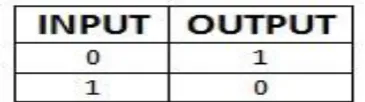
[image:1.595.329.512.705.756.2]From common logic gates, NOT gate is reversible, as can be seen from its truth table below.
The original motivation was that reversible gates dissipate less heat (or, in principle, no heat). In a normal gate, input states are lost, since less information is present in the output than was present at the input. This loss of information loses energy to the surrounding area as heat, because of thermodynamic entropy. Another way to understand this is that charges on a circuit are grounded and thus flow away, taking a small charge of energy with them when they change state. A reversible gate only moves the states around, and since no information is lost, so energy is conserved. Any reversible gate must have the same number of input and output bits. Many reversible gate exists namely Fredkin, Toffoli, QCA1,QCA2 RUG,PERES,TR, in which RUG is Universal Gate and use’s much less number of QCA cells.
3.
REVERSIBLE UNIVERSAL GATE
(RUG)
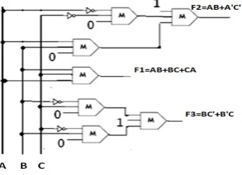
Reversible Universal Gate has a 3-bit input as A, B, and C and 3-bit output as AB+BC+CA, AB+A’C’ and B’C+BC’. The First output is majority function, second output is Universal function and third output is XOR function. Shown in figure 1.
Figure 1: Block Diagram of RUG Gate
RUG logic design is consist of seven majority gates (MV) and four inverter, as shown in figure 1, retains in the simple clocking scheme. For the wire A, B, C it is in different clock zone because to main signal strength. Similarly all MV’s also kept in corresponding clock zones.
RUG gate is universal; this means that for any Boolean function f(𝑥1, 𝑥2,𝑥3,……𝑥𝑚), there is a circuit consisting of RUG gates which takes 𝑥1, 𝑥2,𝑥3,……𝑥𝑚 and some extra bits set to 0 or 1 and outputs 𝑥1, 𝑥2,𝑥3,……𝑥𝑚, f(𝑥1, 𝑥2,𝑥3,……𝑥𝑚), and some extra bits. Essentially, this means that RUG gate can be used to build systems that will perform any desired Boolean computation in a reversible manner. So in this paper we are presenting, how to realize basic logic gates using RUG. The F2=AB+A’C’ in the RUG gate is called Universal Function and which can be used to any logic with a given number of variables with minimum number of wire crossings [15]. So from [15], presence of universal function RUG based QCA circuits are very much cost-effective in terms of number of logic gate, wire crossing, cells count as compared to the designs based on existing reversible gate. This is the concept of a special form of reversible logic with universal functionality. The implementation and effectiveness of RUG has been reported[12] and RUG is very cost effective reversible circuit
4.
REALIZING BASIC LOGIC GATES
USING RUG
The RUG gate takes three input bit A, B, C and produces three bit F1, F2, F3 as output as shown in figure:1; using various input combination on the RUG ; we can form basic logic gates as output. We are presenting how to realize basic logic gates using RUG
4.1
AND, NOT, XOR Gate Realization
[image:2.595.334.511.227.353.2]The logic AND, NOT and XOR can be formed by setting 0 ,A and B as input in respective position in RUG gate as shown in figure 2.
[image:2.595.72.246.309.434.2]
Figure 2: Logic AND, NOT and XOR Gate
4.2
OR Gate Realization
The logic OR can be realized by setting 1 , A and B as input in respective position in RUG gate as shown in figure 3.
Figure: 3. Logic OR Gate
4.3
NAND , NOR Gate Realization
[image:2.595.327.488.427.574.2]5.
EFFECTIVENESS OF RUG
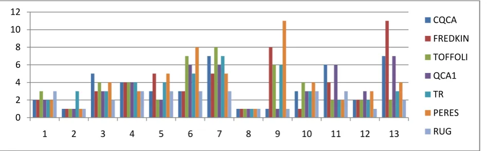
A comparative study on the performance of conventional reversible gates and the RUG in implementing standard function is also reported in table II. The performance in terms of average number of gates required in implementing all thirteen 3-variable standard functions is shown in Fig.5. It
points to the fact that the realization of logic circuits around RUG can result in better cost effective design than that of with other conventional reversible gates. Moreover, the reversible gates such as Feynman, toffoli etc. can’t provide efficient realization of all thirteen standard functions.
[image:3.595.65.539.462.609.2]The figure 5. Bellow present graph in implementation of thirteen standard functions and can be easily seen that the RUG takes less number of gates as compared to other reversible gates.
Figure.5: Number of gates taken to implement 13 standard functions by different reversible gates(y coordinate) vs. 13 standard functions. (X coordinate)
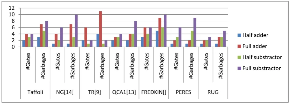
The design capability of RUG is further evaluated in implementing adder operations and subtractor. The cost of a design is estimated in terms of number of reversible gates (Gate) and the number of garbage outputs (garbage) in
implementing of adder/subtractor. The comparative results are noted in Table III. The performance analysis considering the average number of gates and garbage outputs required for all those realization is represented in Fig.6.
0 2 4 6 8 10 12
1 2 3 4 5 6 7 8 9 10 11 12 13
CQCA
FREDKIN
TOFFOLI
QCA1
TR
PERES
Table III: Implementation of adder and subtractor by different reversible gates with gate count
Gates Criteria Half adder Full adder Half subs tractor Full subs tractor Average Value
Tinfoil #Gates 2 4 3 4 3.25
#Garbage’s 3 7 5 8 5.75
NG[17] #Gates 1 4 2 6 3.25
#Garbage’s 1 7 3 10 5.25
TR[19] #Gates 2 6 1 2 2.75
#Garbage’s 4 11 1 2 4.5
QCA1[16] #Gates 2 3 3 4 3
#Garbage’s 2 4 4 8 4.5
FREDKIN #Gates 3 6 4 6 4.75
#Garbage’s 5 9 6 10 7.5
PERES #Gates 1 2 3 6 3
#Garbage’s 1 2 5 9 4.25
RUG #Gates 1 2 2 3 2
#Garbage’s 1 3 3 5 3
The figure 6. Bellow present graph while implementing adder and subtractor and it can be easily seen that the RUG takes less number of gates as compared to other reversible gates.
Figure: 6. Number of gates and garbage’s taken (y-coordinate) vs. TOFFOLI, NG, TR, QCA, FREDKIN, PERES and RUG Gates (x-coordinate) in implementing adder and subtractor
Now it can be easily seen form Figure: 5 and Figure: 6 that the RUG implements all 13 standard function and adder/ subtractor in less number of gates and garbage. So RUG is very efficient for circuit designing while taking energy saving into consideration.
6.
CONCLUSION
RUG is a 3X3 input output reversible logic gate having majority function and universal function and XOR function as outputs; like any other reversible gates RUG do not erase information and ultimately it leads high performance computing. In this paper we have shown how to realize basic logic gates using RUG and also presented effectiveness of RUG gate by comparing it with other existing reversible gate and I
7.
REFERENCES
[1] P.Tougaw and C.Lent, “Logical Devices Implemented using Quantum Cellular Automata”, Journal of Applied Physics,vol.75,no.3,pp.1818-1825,1994.
[2] C.S.Lent and P.D.Tougaw, ”A Device Architecture for
Computing with Quantum Dots,”
Proc.IEEE,vol.85,no.4,pp.541-577,Apr.1997.
[3] W.Porod , ”Quantum-Dot Devices and Qunatum-Dot Cellualr Automata”, hirer J Bi/urcorionond Cltaor,YO7I.,no.10, pp.2199-2218,1997.
[4] I.Amlani , ”Digital Logic Gate Using Quantum-Dot Cellular Automata”, Science v01.284,pp.289-291,1999.
0 2 4 6 8 10 12
#G
at
es
#G
ar
b
ages
#G
at
es
#G
ar
b
ages
#G
at
es
#G
ar
b
ages
#G
at
es
#G
arb
age
s
#G
at
es
#G
ar
b
ages
#G
at
es
#G
ar
b
ages
#G
at
es
#G
ar
b
ages
Taffoli NG[14] TR[9] QCA1[13] FREDKIN[] PERES RUG
Half adder
Full adder
Half substractor
[image:4.595.66.551.350.519.2][6] R.Landaurer, ”Irreversibility and Heat Generation in the Computational Process”, IBM Journal of Research and Development,vol.5,pp 183-191,1961.
[7] I.Amlani ,”Demonstration of a Functional Quantum-Dot Cellular Automata Cell” , J.Vaccume Science and Technology, Cellular Automata Cell , J. Vacuum Science and Technology.
[8] I.Amlani ,”Digital Logic Gate Using Quantum-Dot Cellular Automata” , Science ,pp.289-291,1999.
[9] G.L. Snider, ”Experimental Demonstration of Quantum-Dot Cellular Automata”, Semiconductor Science Technolgy,vol.13,pp.A130-A134,1998.
[10] K.Hennessy and C.Lent, ”Clocking of Molecular Quantum-Dot Cellular Automata”, Journal Of Vacuum Science and Technology,vol.19,no.5,pp.1752-1755,2001. [11] Momenzadeh, M, Jing Huang, Tahoori, M.B., Lombardi,F.
,’Characterization, test, and logic synthesis of and-or-inverter (AOI) gate design for QCA implementation’, in IEEE Transaction on Computer-Aided Design of Integrated Circuits and Systems, Vol. 24, pp-1881-1893 No. 12, December,2005.
[12] Bibhash Sen, Divyam Saran, Mousumi Saha and B K Sikdar, “Synthesis Of Reversible Universal Logic Around QCA With Online Testability”, in Proceedings of 2nd IEEE Conference ISED'11, Page(s): 236 - 241 Kochi,India, 2011.
[13] C.H. Bennett, ’Logical Reversibility of Computation’, IBM J.Research and Development, pp. 525-532, November 1973.
[14] J. Timler and C. Lent, ’Maxwells demon and quantum dot cellular automata’, Journal of Applied Physics, vol.94, no. 2,pp. 1050, 2003.
[15] Yinshui Xia, Keming Qui , ”Design and Application of Universal Logic Gate Based on Quantum-Dot Cellular Automata”, pp.335-338,2008.
[16] X. Ma, J Huang, C Metra and F Lombardi, 'Testing Reversible lD Arrays for molecular QCA', in Proceedings of 21st IEEE international symposium on Defect and Fault Tolerence in VLSI(DFT'06) 2006. [17] Azad Khan and Md M. H, 'Design of full adder with
reversible gate', Proceedings of Internation conference on Computer and information Technology, Dhaka, 2002.
[18] Himanshu Thapliyal and Nagarajan Ranganathan, 'Conservative QCA Gate(CQCA) for Designing Concurrently Testable Molecular QCA circuits ',in Proceedings of 22nd IntI. conference on VLSI design, New Delhi,Jan, pp 511-516,2009.