Congestion Control in Real Time Applications
S. Vishnu Vardhan
M.Tech Dept of CSE
JNTUACEP
P. Chenna Reddy
Phd, Associate Professor Dept of CSE
JNTUACEP
ABSTRACT
The amount of traffic generated by RTAs has increased substantially over the years. RTA will face congestion where there is any form of bottleneck restricting traffic. This will result in packet loss or delayed traffic which is unacceptable for RTAs. Therefore it is desirable for RTAs to implement congestion control mechanism to improve the stability of networks.
TCP Friendly Rate Control (TFRC) is a congestion control algorithm that provides a smooth transmission rate for RTAs. TFRC is a congestion control mechanism for unicast flows operating in a best effort internet environment. It is reasonably fair when competing for bandwidth with TCP flows in congested network, but has a much lower variation of throughput over time compared with TCP. In this work we use NS2, the network simulator for simulation of TFRC. TFRC is simulated in different environments, limitations are identified and modifications are proposed.
Keywords
Congestion, RTAs, TFRC, TCP, VoIP, Video Conference
1.
INTRODUCTION
The Transmission Control Protocol (TCP) is connection oriented protocol that provides reliable and ordered delivery of packet and also provides end-to-end congestion control mechanism. Data transfer applications such as FTP, HTTP and SMTP are based on TCP. But over Internet, the use of RTAs such as VoIP, video conferences, instant messaging is constantly growing. Estimates show that these streaming media accounted for 30% of overall internet traffic.
The user datagram protocol (UDP) is one of the protocols of the Internet protocol suite. Using UDP, programs on networked computers can send datagram’s to one another. UDP applications can send data at constant bit rate where it does not guarantee reliability or ordering in the way that TCP does. It is one of the non TCP based protocol. This non TCP flow cannot adjust their flow rate when congestion is detected where it continue to send at original rate. So these non TCP applications do not have congestion control mechanism and do not share bandwidth fairly with TCP based applications. A new congestion control protocol for datagram transport was defined i.e., TFRC standardized by Internet Engineering Task Force (IETF). It provides a smooth transmission rate for real-time applications.It is reasonably fair when competing for bandwidth with TCP flows. In RFC 3448 a TFRC algorithm is defined based on model of TCP and it is designed for continues flow traffic. This is not suitable for the applications whose transmission is variable bit rate. Datagram congestion control protocol (DCCP) is recently standardized protocol. DCCP supports multiple congestion control algorithms and these will be selected through its Congestion Control ID
(CCID). Three CCIDs are now standardized by IETF. CCID2 is a window based congestion control algorithm similar to TCP, CCID3 is a TCP-Friendly Rate Control algorithm, and CCID4 is a TCP-Friendly Rate Control for Small Packets (TFRC-SP).
In this paper, we present results of experimental evaluation of the performance DCCP (CCID3) TCP-Friendly rate control over wired environments.
2.
HOW TFRC WORKS
TFRC functionalities are located at the receiver’s end. TFRC can adjust its transmission rate based on the TCP throughput equation shown below:
T(Bps)
=
Where:
s is segment size in bytes, RTT is round trip time in seconds,
RTO is the TCP retransmission timeout value in seconds,
P is the loss event rate.
To calculate loss event rate, receiver needs to find loss event of one or more packets lost or marked in particular RTT. Timestamp along with RTT is used by receiver to determine losses belong to same loss event or not. RTT is used to determine when to send feedback packets.Loss event rate and RTT is then fed to TCP throughput equation at senders end to calculate the TCP friendly rate. Sender then adjusts its sending rate according to this calculated rate. TFRC provides smooth sending rate while still providing sufficient responsiveness to competing traffic. It allows moderate bandwidth changes and is more appropriate to video streaming.
2.1 Improvements of TFRC
The original specification of TFRC-RFC 3448 is suited for many multimedia streaming applications, where it is used for continuous flow of data is available at sender. It is not useful for the applications like voice over IP (VoIP) and video conference characterized by periods of higher (but limited) transmission rate, separated by periods in which much less (which we call ‘data-limited’), or without transmission of data ( which we call ‘idle periods’). This type of applications required variable media rate at senders.
few RTTs sending rate will be less than media rate and this delay is called start-up delay. During an idle period (no data can be transferred) for a period of 4RTTs, TFRC reduces the allowed sending rate by one half for every no feedback timer expiry (4RTT). The rate can be reduced to minimum of 2 packets for each RTT. When the application restarts (starts sending data) TFRC must slow start back from idle period rate to the given rate. It takes time to recover from idle period to maintain media rate.
DCCP provides features of unreliable flow of datagram’s with acknowledgements, reliable handshake for connection setup and teardown. DCCP working group also updated the algorithms in RFC 3448, leading to RFC 5348. It is intended to provide better support to streaming media applications like voice over IP (VoIP) and video conference during data limited and idle periods. RFC 5348 can share bandwidth fairly with the TCP based applications.
In TFRC (RFC 5348) during slow-start phase, the initial rate of the sender was increased to 4 packets per RTT. The behavior after an idle period was updated in the absence of loss, the sending rate is not reduced below 4 packets per RTT or equal to the initial rate. After idle and data-limited period double sending rate is not limited by receiver rate in congested network.
The development and specification of TFRC is still ongoing in the IETF. One focus of the current IETF work is on variants of the existing mechanisms that are better suited for bursty interactive traffic. It is motivated by the observation that the original TFRC model assumes transmission of MTU-sized segments. Applications that transmit short segments, such as voice audio, achieve a significantly lower throughput under TFRC. Similarly, video encoders employing motion compensation may result in varying media rates. It is motivated by the observation that the original TFRC model.
3.
QOS REQUIREMENTS OF VOIP
AND VIDEO CONFERENCE
Voice over IP and video conference both are two-way interactive applications that function within time frame that the user senses as immediate (or) current.
Three quality factors are required for both VoIP and video conference.
Loss should be no more than 1 percent.
One–way latency should be no more than 150ms. Jitter should be no more than 30ms.
These quality requirements must be satisfied for both VoIP and video conference. VoIP requires low bandwidth of range 21 to 320 kbps with small packet size and for Videoconference it requires high bandwidth, minimum of 384 Kbps with large packet size.
4.
SIMULATION
:4.1 Methodology
The performance of TCP when operated along with UDP traffic is studied. The performance of RFC5348 for VoIP and Video conference applications is studied. In this paper, we are using
RFC 5348 with slow media rate for VoIP traffic with an encoding rate of 64 Kbps and packet size of 160 bytes and for
video conference we are using high media rate with an encoding rate of 448 Kbps and packet size of 1000 bytes. The network simulator NS-2, version 2.34 is used for simulation. In addition to NS-2, a set of tools, mainly Bash scripts and AWK filters, to post-process the output trace files generated by the simulator are developed. In order to evaluate the performance, multiple experiments have been set up.
At first, simulation for TCP and UDP traffic is presented in wired network. The topology we are using is dumbbell topology with bottleneck traffic of capacity 2 Mbps at (R1-R2)
and other links capacity of 5Mbps. The topology is shown in Fig. 1.
Figure 1: simulation topology
By keeping TCP window size constant and increasing the UDP rate with 0.5 Mbps. Packet size of TCP and UDP is same with 1000 bytes. TCP traversed between (N0-N3) and UDP traversed between (N1-N2).
4.2 Metrics
4.2.1 Packet Delivery Ratio:
It is the ratio of number of packets received by the destination to number of packets sent from the source.
4.2.2 Average End-to-End Packet Delay:
It is the average delay of all the packets while traveling from source node to destination node.
4.2.3 Packet Loss Ratio:
It is the ratio of number of lost packets to the sum of number of packets received and number of lost packets
[image:2.595.319.533.219.356.2]4.3 Simulation Results
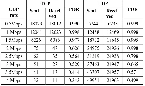
Table 1: The impact of UDP on TCP
UDP rate
TCP
PDR
UDP
PDR
Sent Recei
ved
Sent Recei ved
0.5Mbps 18029 18012 0.990 6244 6238 0.999
1 Mbps 12041 12023 0.998 12488 12469 0.998
1.5Mbps 6226 6086 0.977 18732 18645 0.995
2 Mbps 75 47 0.626 24975 24926 0.998
2.5Mbps 62 35 0.564 31219 24938 0.798
3 Mbps 51 27 0.529 37463 24947 0.665
[image:2.595.311.550.630.772.2]0 0.2 0.4 0.6 0.8 1 1.2
0.5 1 1.5 2 2.5 3 3.5 4
[image:3.595.318.548.98.239.2]TCP UDP
Figure 2: Comparison of Packet delivery ratio of TCP and UDP
0 50 100 150 200 250
0.5 1 1.5 2 2.5 3 3.5 4
[image:3.595.56.285.100.234.2]TCP UDP
Figure 3: Comparison of End-to-End Delay of TCP and UDP
The results show that UDP does not share bandwidth fairly with the TCP traffic. TCP reduces the sending rate in reaction to congestion. UDP does not react to congestion and it continues to send the data at the same rate. This makes UDP take advantage over TCP and ultimately may result in instability of the network. The results are shown in Table 1. Packet delivery ratio and end-to-end delay are shown in Fig.2 and Fig. 3 respectively. X-axis represents the bandwidth of bottleneck link in both the graphs. End-to-end delay is in milliseconds.
4.4 Fairness of TFRC with TCP
[image:3.595.56.280.249.422.2]In this section TFRC (RFC5348) is compared with TCP by operating both at the same time. Packet size of TFRC and TCP is same i.e., 1000 bytes. The topology is as shown in Fig. 1.
Table 2: Comparison of TFRC with TCP
0.97 0.975 0.98 0.985 0.99 0.995 1
256&30 384&50 512&70 768&90 1024&100
TCP TFRC
Figure 4: Packet Delivery Ratio of TCP and TFRC
315 320 325 330 335 340 345 350
256&30 384&50 512&70 768&90 1024&100
[image:3.595.318.537.268.432.2]TCP TFRC
Figure 5: End to End Delay of TCP and TFRC
The results show that TFRC shares bandwidth fairly with the TCP. The packet delivery ratio metric is plotted in Fig. 4. On X-axis (TFRC rate, TCP window size) are represented. Table 2 presents the more detailed results. End-to-End delay results are shown in Fig. 5. The interesting observation to be made is TFRC also reduces the data rate in reaction to congestion and hence is fair to TCP.
4.5 VoIP performance
This section analyzes the performance of VoIP interactive media flows using “dumbbell” topology having bottleneck link capacity of 100Kbps at (R1-R2) and other links capacity being 1Mbps. A G.711 VoIP codec is assumed, with 64 Kbps rate and packet size 160 bytes.
Table 3: comparison of TFRC with UDP
TFR C rate
in Kbps
TC P Win dow size
TCP
PDR
TFRC
PDR Sent Rece
ived Sent
Rece ived
256 30 8860 8831 0.9967 3197 3187 0.9968
384 50 7324 7271 0.9927 4795 4763 0.9933
512 70 6416 6359 0.9911 5751 5684 0.9883
768 90 7013 6952 0.9913 5180 5086 0.9818
1024 100 6772 6698 0.9890 5453 5343 0.9798
Simulation
time Sent Received Drop
TFRC
5 ms 332 331 0
10 ms 672 670 0
50 ms 3386 3386 0
100 ms 6780 6778 0
UDP
5 ms 630 574 6
10 ms 1271 1160 60
50 ms 6396 5847 498
[image:3.595.310.548.628.749.2]0 2 4 6 8 10
5 10 50 100
TFRC UDP
Figure 6: Packet Loss Ratio of TFRC and UDP
0 100 200 300 400 500
5 10 50 100
[image:4.595.318.543.72.386.2]TFRC UDP
Figure 7: End to End Delay of TFRC and UDP
The results show that smooth transmission of TFRC. It is able to compete with UDP and prevent UDP from exploiting its share of the bandwidth. The Packet Loss ratio metric is plotted in Fig. 6. On X-axis (simulation time of TFRC and UDP at 5, 10, 50, 100 milliseconds) are represented. Table 3 presents the more detailed results. End-to-End delay results are shown in Fig. 7.
4.6 Video performance
This section analyzes the benefits of video conference over RFC 5348. A packet size of 1000 bytes is taken. The bottleneck link capacity is set to 1Mbps at (R1-R2). Video
conferencing using variable bit rate. It is initially set to 448Kbps, at 20 seconds set rate is minimum rate of 20kbps, at 50 seconds set rate is 1Mbps and at 80 seconds set rate is 448Kbps.
Table 4: comparison of TFRC with UDP
Simulation
time Sent Received Drop
TFRC
20 ms 2230 2230 0
50 ms 2380 2380 0
70 ms 4889 4788 71
100 ms 8544 8420 82
UDP
20 ms 2230 2228 0
50 ms 2380 2380 0
70 ms 7380 4878 2451
100 ms 12118 8416 3701
0 10 20 30 40
20 50 70 100
TFRC UDP
Figure 8: Packet Loss Ratio of TFRC and UDP
0 50 100 150 200 250
20 50 70 100
[image:4.595.56.283.75.221.2]TFRC UDP
Figure 9: End to End Delay of TFRC and UDP
The Packet Loss ratio metric is plotted in Fig. 8. On X-axis (simulation time of TFRC and UDP at 20, 50, 70, 100 milliseconds) are represented. Table 3 presents the more detailed results. End-to-End delay results are shown in Fig. 9.
5.
CONCLUSION
The Performance of TCP when operated along with UDP is compared and simulation results show that TCP suffers with UDP traffic. Simulation results also show that TFRC (RFC5348) can share bandwidth with TCP flow efficiently in wired environment. The specification of RFC 3448 poorly supported interactive multimedia applications where padding can be used to guarantee the required media rate for RTA applications. Where RFC5348 does not require padding, which consumes unnecessary network capacity. RFC 5348 also increases the sending rate compared to RFC 3448. The performance of RFC5348 works fine with VoIP and video conference applications during variable bit rate through bottleneck capacity. We therefore expect this new standard to further encourage the use of a standard-based congestion control for Real Time Applications.
6.
REFERENCES
[1] M. Handley, S. Floyd, J. Padhye, J. Widmer, TCP Friendly Rate Control (TFRC): Protocol Specification, IETF RFC 3448, January 2003.
[2] M. Handley, S. Floyd, J. Padhye, J. Widmer,TCP-Friendly Rate Control (TFRC): Protocol Specification, IETF RFC 5348, April 2008.
[3] QoS requirements of VoIP and video conference by Cisco. <http://www.ciscopress.com/articles>
[image:4.595.56.283.251.408.2][5] M. Allman, V. Paxson, W. Stevens TCP Congestion Control, IETF RFC5681, September 2009.
[6] S. Floyd, E. Kohler, J. Padhye, Profile for Datagram Congestion Control Protocol (DCCP) Congestion Control ID 3: TCP-Friendly Rate Control (TFRC), IETF RFC 4342, March 2006.
[7] B. Zhou, C. Fu, V. Li, TFRC Veno: an Enhancement of TCP Friendly Rate Control over Wired/Wireless Networks, ICNP, October 2007, pp. 216–225.
[8] S. Floyd, M. Handley, E. Kohler, Problem Statement for the Datagram Congestion Control Protocol (DCCP), IETF RFC 4336, March 2006.
[9] S. Floyd, E. Kohler, Profile for DCCP Congestion Control ID 4: the Small-packet Variant of TFRC Congestion Control, IETF RFC 5622,August 2009. [10]M. Chen, A. Zakhor, Rate control for streaming video