http://dx.doi.org/10.4236/cs.2015.68018
How to cite this paper:Walde, N. and Ahmad, S.N. (2015) New Voltage Mode Sinusoidal Oscillator Using Voltage Diffe-rencing Transconductance Amplifiers (VDTAs). Circuits and Systems, 6, 173-178. http://dx.doi.org/10.4236/cs.2015.68018
New Voltage Mode Sinusoidal Oscillator
Using Voltage Differencing
Transconductance Amplifiers (VDTAs)
Nisha Walde
*, Syed Naseem Ahmad
Department of Electronics & Comm. Engineering, Jamia Millia Islamia, New Delhi, India Email: *[email protected], [email protected]
Received 19 June 2015; accepted 15 August 2015; published 19 August 2015
Copyright © 2015 by authors and Scientific Research Publishing Inc.
This work is licensed under the Creative Commons Attribution International License (CC BY). http://creativecommons.org/licenses/by/4.0/
Abstract
The purpose of this paper is to introduce a new electronically controlled voltage mode sinusoidal oscillator (VMSO) using Voltage Differencing Transconductance Amplifiers (VDTA). The proposed circuit provides electronic control of ω0 and independent condition of oscillation (CO). It is found
that the oscillator works very satisfactorily and pure sinusoidal waveforms are available at the outputs. The PSPICE simulation confirms the theoretical results. The proposed oscillator circuit employs only two VDTAs, along with two grounded capacitor and single grounded resistor. The circuit exhibits low active and passive sensitivities for ω0. Simulation results are obtained by using
PSPICE software with TSMC CMOS 0.18 um process parameters.
Keywords
Voltage Differencing Transconductance Amplifier (VDTA), Voltage-Mode Circuit, Oscillator
1. Introduction
In recent years the focus has been on the design of various applications based on advanced analog building blocks [1]-[4]. Sinusoidal oscillators find wide applications in communication engineering, electronic instru-mentation and control systems [5] [6]. The voltage differencing transconductance amplifier (VDTA) is an active versatile building block used in the realization of analog signal processing circuits and analog wave generation. It is also attractive due to its capability of adjusting the output current gain.
However, these circuits suffer from
• Excessive use of passive elements, especially external resistors.
• Use of a floating capacitor, which is not convenient to further fabrication in IC.
• Oscillation conditions (CO) and oscillation frequencies cannot be independently controllable.
Various filters and oscillators are designed using active building blocks such as CFTAs [8] [9], CCCFTAs [10], CDTA, VDTA, CFA, CC-II [11]-[18].
The purpose of this paper is to present new voltage mode sinusoidal oscillator by using two VDTAs, two grounded capacitors and one resistor. PSPICE simulation results are provided, which verify the workability of the proposed circuit. The resulting circuit is low-power and provides independent control of the condition of os-cillation (CO) and frequency of osos-cillation (FO). The important feature of VDTA is that this new element exhi-bits two different values of transconductances so that several applications such as oscillator, filters, inductance and FDNR (frequency dependent negative resistor) simulator can be realized with a single active block employ-ing one or two capacitors. One more important feature is that this block can be used easily at transconductance mode applications such that the input terminals is voltage and output terminals is current. The proposed circuit employs minimum number of passive and active components. The use of additional VDTA facilitates the achievement of independent control of ω0, which is an attractive feature of the circuit.
2. Circuit Description
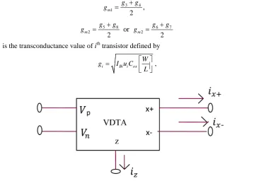
The Voltage Differencing Transconductance Amplifier (VDTA), whose schematic symbol is shown in Figure 1, consists of an input current follower that transfers the input current to the z terminal and an output transconduc-tance amplifier stage, which is used to convert the voltage at the z terminal into output currents. Relations be-tween the individual terminals of VDTA can be described by the following hybrid matrix:
1 1
2
2
0
0 0
0 0
z m m VP
x m VN
x m Z
I g g V
I g V
I g V
+
−
−
=
−
(1)
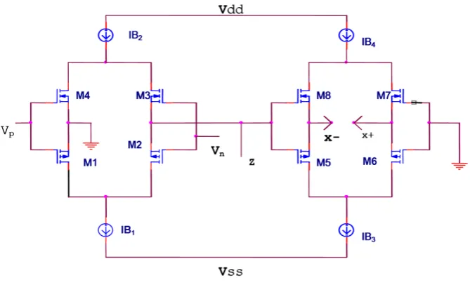
where gm is transconductance gain of the VDTA which is given by Equations (2) & (3). Internal construction of VDTA used for simulation is shown in Figure 2. The introduced circuit employs two transconductances. In-put and outIn-put transconductances parameters of VDTA element in the circuit are determined by the transcon-ductance of outputs transistors. It can be approximated as
3 4
1 ,
2
m
g g
g = + (2)
5 8 6 7
2 or 2
2 2
m m
g g g g
g = + g = + (3)
where gi is the transconductance value of ith transistor defined by
i Bi i ox
W
g I u C
L
=
[image:2.595.130.514.453.709.2] , (4)
Figure 2. Internal construction of VDTA using CMOS used for simulation.
i
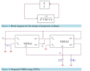
u is (i = n, p) the mobility of the carrier for NMOS (n) and PMOS (p) transistors, Cox is the gate-oxide capa-citance per unit area, W is the effective channel width, L is the effective channel length and IBi is bias current of ith transistor. The proposed VMSO using VDTA [18] is shown in Figure 4. It consists of 2 VDTAs, 2 grounded capacitors and one resistor.
3. Proposed Circuit Realization of VMSO Using Voltage Differencing
Transconductance Amplifier (VDTA)
The oscillator is designed by cascading an inverting second order low-pass filter and the lossless integrators as shown in Figure 3. From block diagram as shown in Figure 3, we obtain the characteristic equation of a sinu-soidal oscillator as
3 2
0
s +bs +as ck+ = (5a) Hence, from Equation (5a), the condition of oscillation (OC) and frequency of oscillation (FO) can be written as
OC :
ab
=
ck
(5b)and
0 a
ω
= (5c)From Equation (5a), if a = c, the oscillation condition and oscillation frequency can be adjusted independently, i.e. the oscillation condition can be controlled by b and k, while the oscillation frequency can be tuned by a. The proposed voltage mode sinusoidal oscillator using VDTA is shown in Figure 4. The frequency of oscillation (FO) and condition of oscillation (CO) are found to be
(
)
1 2
0 4
1 2
m
m m
g
g g
c c
ω = +
If c1=c2=c
(
)
0 1 2 4
FO : 1 gm gm gm
c
ω = + (6)
(
2 4)
1
CO : 1 gm gm 0
R − + ≤ (7)
Figure 3. Block diagram for the design of proposed oscillator.
Figure 4. Proposed VMSO using VDTA.
oscillation is controlled independently by gm1 which is independent of CO. The voltage mode transfer function obtained from Figure 4 is
( )
( )
(
2 4)
2
1 1
m m
g g
V s
V s sC
+
= − (8)
Therefore, the proposed circuit provides two voltage mode sinusoidal oscillations across output simulta-neously.
4. Non Ideal and Sensitivity Analysis
The FO and CO for the circuit shown in Figure 5 are given as:
(
) (
)
(
)
(
)
1 2 4 2 4
1
1 2
0
FO :
1 1 1 1 1
m m m m m
x x z x
p z
g g g g g
R R R R R
C C C C
ω − + −
+ + + + − +
+
=
+ (9)
(
1)
(
2) (
2 4)
(
1)
1
1 1 1
: 1 0
CO P z m m p
x z x
C C C C g g C c
R R+ R R−
+ + + + + − + + ≤
(10)
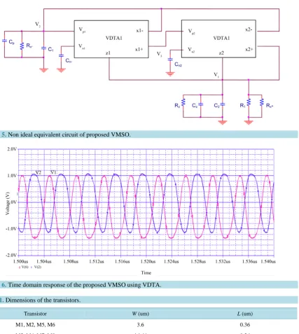
From Figure 5, it shows that parasitic capacitances Cp and Cz are in parallel with the external capacitances C1
and C2 respectively. Therefore, the influence of the parasitic capacitances can be eliminated easily by reducing
the values of external capacitances. If Rx− is infinite, the frequency of oscillation and condition of oscillation are independently tunable even under the influence of VDTA parasitic. The effect of changes in active and pas-sive element values is determined by evaluating sensitivity coefficients which are found to be
0 0 0 0 0 0
1 2 4 1 1 2
1 1
, 0,
2 2
m m m
g g g R C C
Sω =Sω =Sω = Sω = Sω =Sω = − (11)
Therefore, all the active and passive sensitivities of ω0 are low. The non ideal equivalent circuit of proposed
5. Simulation Results
The performance of the proposed voltage mode sinusoidal oscillator circuit in Figure 4 has been verified by PSPICE simulation results. The PMOS and NMOS transistors have been simulated by respectively using the parameters of a 0.18 µm TSMC CMOS technology [11] [18]. The aspect ratios of PMOS and NMOS transis-tors are indicated in Table 1. The circuit was biased with ±0.9 V power supply voltage, VBB= −0.55 V,
1 2 3 4 150 A
B B B B
I =I =I =I = µ . The transconductance values of VDTA are 1 2 3 4 636.3uA V
m m m m
g =g =g =g =
and the parasitic capacitance at the Z terminal is specified as Cp = 0.15 pF. The values of the capacitors were
chosen as: C1=C2 =1 nf and R1=1.5 kΩ. In Figure 6, time domain response of the proposed VMSO using VDTA is shown using PSPICE 16.3 which confirms the validity of design equations of oscillator shown in Equ-ations (6) and (7). Frequency of oscillation was found to be f0 = 15.56 MHz.
[image:5.595.112.540.229.707.2]Figure 5. Non ideal equivalent circuit of proposed VMSO.
Figure 6. Time domain response of the proposed VMSO using VDTA.
Table 1. Dimensions of the transistors.
Transistor W (um) L (um)
M1, M2, M5, M6 3.6 0.36
[image:5.595.88.544.667.718.2]6. Conclusion
In this paper, a new VMSO using VDTAs (Voltage Differencing Tranconductance Amplifier) is presented as shown in the PSPICE. The circuit is realized by using two VDTAs, two grounded capacitors and one resistor. The circuit has the features of low active and passive sensitivities, low voltage supply and large bandwidth. It has low-input and high-output impedances and is also convenient for electronic controllability through tran-sconductance gain gm of VDTAs.
References
[1] Sedra, A. and Smith, K.C. (1970) A Second-Generation Current Conveyor and Its Applications. IEEE Transactions on Circuit Theory, 17, 132-134. http://dx.doi.org/10.1109/TCT.1970.1083067
[2] Herencsar, N., Koton, J., Vrba, K. and Lahiri, A. (2010) Current-Controlled CFTA-Based Current-Mode SITO Uni-versal Filter and Quadrature Oscillator. 2010 International Conference on IEEE Explorer Digital Library Applied Electronics (AE),Pilsen, 8-9 September 2010, 1-4.
[3] Walde, N. and Ahmad, S.N. (2014) New Current-Mode Second Order Filter Using Current Feedback Amplifiers (CFAs). International Journal of Computer Applications, 86, 10-12. http://dx.doi.org/10.5120/15068-3432
[4] Herencsar, N., Koton, J., Vrba, K. and Misurec, J. (2009) A Novel Current-Mode SIMO Type Universal Filter Using CFTAs. Contemporary Engineering Sciences, 2, 59-66.
[5] Abuelma’atti, M.T. and Al-Qahtani, M.A. (1998) Low Component Second-Generation Current Conveyor-Based Mul-tiphase Sinusoidal Oscillator. International Journal of Electronics, 84, 45-52.
[6] Skotis, G.D. and Psychalinos, C. (2010) Multiphase Sinusoidal Oscillators Using Second Generation Current Con-veyors. AEU—International Journal of Electronics and Communications, 64, 1178-1181.
http://dx.doi.org/10.1016/j.aeue.2009.11.013
[7] Wu, D.S., Liu, S.I., Hwang, Y.S. and Wu, Y.P. (1995) Multiphase Sinusoidal Oscillator Using Second-Generation Current Conveyors. International Journal of Electronics, 78, 645-651. http://dx.doi.org/10.1080/00207219508926198
[8] Walde, N. and Ahmad, S.N. (2015) Resistorless Switched Capacitor Biquad Filter using Current Follower Transcon-ductance Amplifier. IEEE Explorer International Conference on Computing for Sustainable Global Development, New Delhi, 11-13 March 2015, 2185-2189.
[9] Lahiri, A. (2010) Resistorless Mixed-Mode Quadrature Sinusoidal Oscillator. International Journal of Computer and Electrical Engineering, 2, 63-66.
[10] Herencsar, N., Koton, J. and Vrba, K. (2009) Electronically Tunable Phase Shifter Employing Current-Controlled Current Follower Tranconductance Amplifiers (CCCFTAs). International Conference on Telecommunications and Signal Processing, Hungary, 26-27 August 2009, 54.
[11] Prommee, P. and Dejhan, K. (2002) An Integrable Electronic-Controlled Quadrature Sinusoidal Oscillator Using CMOS Operational Transconductance Amplifier. International Journal of Electronics, 89, 365-379.
http://dx.doi.org/10.1080/713810385
[12] Walde, N. and Ahmad, S.N. (2015) Realization of a New Current Mode Second-Order Biquad Using Two Current Follower Transconductance Amplifiers (CFTAs). Circuits and Systems, 6, Article ID: 56374.
[13] Biolek, D., Senani, R., Biolkova, V. and Kolka, Z. (2008) Active Elements for Analog Signal Processing: Classifica-tion, Review, and New Proposals. Radioengineering, 17, 15-32.
[14] Prasad, D. and Bhaskar, D.R. (2012) Electronically Controllable Explicit Current Output Sinusoidal Oscillator Em-ploying Single VDTA. ISRN Electronics, 2012, Article ID: 382560. http://dx.doi.org/10.5402/2012/382560
[15] Walde, N. and Ahmad, S.N. (2015) Resistorless Current Mode Electronically Tunable Multiphase Sinusoidal Oscillator Using CFTAs. Communicated in Contemporary Engineering Sciences, in June.
[16] Prasad, D., Bhaskar, D.R. and Srivastav, M. (2014) Voltage Mode Quadrature Oscillator Employing Single VDTA and Grounded Passive Elements. Contemporary Engineering Sciences, 7, 1501-1507.
[17] Satansup, J., Pukkalanun T. and Tangsrirat, W. (2012) Electronically Tunable Single-Input Five-Output Voltage-Mode Universal Filter Using VDTAs and Grounded Passive Elements. Circuits, Systems, and Signal Processing, 32, 9492. [18] Yesil, A., Kacar, F. and Kuntman, H. (2011) New Simple CMOS Realization of Voltage Differencing