1037852-0001 Revision A September 4, 2008
HX System
System Overview
Release 1.2.7
Copyright © 2008 Hughes Network Systems, LLC
All rights reserved. This publication and its contents are proprietary to Hughes Network Systems, LLC. No part of this publication may be reproduced in any form or by any means without the written permission of Hughes Network Systems, LLC, 11717 Exploration Lane, Germantown, Maryland 20876.
Hughes Network Systems, LLC has made every effort to ensure the correctness and completeness of the material in this document. Hughes Network Systems, LLC shall not be liable for errors contained herein. The information in this document is subject to change without notice. Hughes Network Systems, LLC makes no warranty of any kind with regard to this material, including, but not limited to, the implied warranties of merchantability and fitness for a particular purpose.
Trademarks
Hughes and Hughes Network Systems are trademarks of Hughes Network Systems, LLC. All other trademarks are the property of their respective owners.
Revision record
Revision Date of issue Scope
Contents
Chapter 1
Overview . . . .1
Scope . . . .1 Audience. . . .1 Target Markets . . . .2 Related publications . . . .2What’s new in this release . . . .3
Multiple Outroutes . . . .3
Inroute Management by NMSS . . . .3
Inroute CIR with Min, Guaranteed and Max bandwidth . . . . .3
Configurable Demodulation System (CDS) . . . .3
CACTI Network Manager . . . .4
Expansion rack option . . . .4
The HX System . . . .4
Innovative features . . . .6
Broadband applications . . . .7
HX System architecture . . . .8
HX System star topology . . . .8
HX gateway . . . .8 Fixed gateway (GW) . . . .8 Transportable gateway (TGW) . . . .8 HX satellite routers. . . .9 Network segments . . . .9 Gateway segment . . . .9
Satellite router segment . . . .9
Space segment . . . .9
Wide area network segment . . . .9
System management . . . .10 Information flow. . . .11
Chapter 2
Subsystems . . . .13
Interface subsystem . . . .15 IP gateways. . . .15Radio frequency (RF) subsystem . . . .16
Radio frequency terminal . . . .16
Uplink subsystem . . . .16
Satellite gateway. . . .16
DVB and DVB-S2 modulators. . . .17
Timing subsystem. . . .18
Timing generator . . . .18
Timing unit . . . .18
Closed loop timing . . . .19
Timing subsystem physical constraints . . . .19
Downlink subsystem . . . .19
Configurable Demodulation Subsystem. . . .19
CDDM . . . .20
CDIM . . . .20
IF Subsystem-Turbo Code system . . . .20
Return channel components . . . .20
Return channel demodulator. . . .20
Return channel control processor . . . .21
Return channel IF distribution . . . .21
Dynamic network control cluster (DNCC). . . .21
Control Processor . . . .21
Systems with CDS . . . .22
Systems with IFSS-TC . . . .22
Network Management Support Services (NMSS) subsystem . .22 Vision . . . .23
Conditional access controller . . . .23
Management file server . . . .23
Web-based auto-commissioning . . . .23
Satellite-based commissioning . . . .24
UEM database . . . .24
Special services gateway . . . .24
Quality monitor PC. . . .24
CACTI Network Manager . . . .25
Local area networks . . . .25
Gateway LAN. . . .25
Management VLAN . . . .25
Satellite VLAN . . . .25
Return Channel LAN . . . .26
CP VLAN . . . .26 Enterprise LAN/VLAN . . . .26
Chapter 3
Network management . . . .27
Overview . . . .27 NMSS server components . . . .29 Configuration management . . . .29Gateway component configuration. . . .29
Remote site component configuration . . . .29
Software configuration management . . . .30 Configuration interfaces . . . .30 Fault management . . . .31 Status monitoring . . . .31 Alarms . . . .31 Performance management . . . .32 Real-time statistics . . . .32 Historical statistics . . . .32 Security management . . . .32 Operator security . . . .32
Network component security . . . .32
Configuration NMDs . . . .32
Management NMDs . . . .33
Encryption key management . . . .33
Component control . . . .34
HX gateway control . . . .34
Remote site control. . . .34
Chapter 4
Network security . . . .35
Data encryption . . . .35
DES-encrypted outbound channel . . . .35
Two-way IPSec encryption . . . .35
Network security features. . . .36
Firewalling . . . .36
Fenced Internet . . . .37
Chapter 5
Bandwidth management . . . .39
Bandwidth management overview . . . .39
Bandwidth assignments . . . .40
Inroute bandwidth pooling . . . .40
Dynamic stream services . . . .42
Advanced bandwidth management techniques . . . .43
Preassigned CBR services . . . .43
Outroute CBR . . . .43
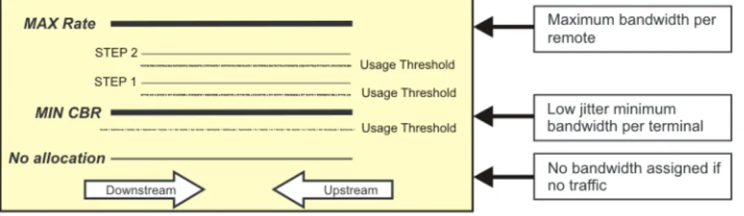
Adaptive CBR with step increments . . . .43
CIR . . . .45
Outroute CIR . . . .46
Best effort services . . . .47
Bandwidth terminology . . . .47
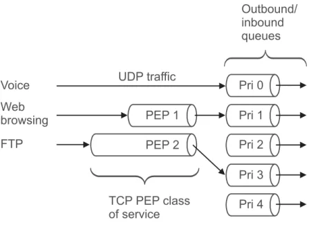
Traffic prioritization . . . .47
Chapter 6
IP features. . . .51
Network layer features . . . .51
Bandwidth conservation features . . . .51
IP packet payload compression . . . .52
Inbound header compression . . . .52
Performance Enhancing Proxy (PEP V3). . . .52
TCP spoofing . . . .52
PEP and TCP payload compression . . . .52
TurboPage. . . .53
IP packet delivery prioritization . . . .53
NAT/PAT . . . .53
Port mapping . . . .54
VLAN Tagging. . . .54
IPGW VLAN tagging. . . .54
Remote VLAN tagging. . . .55
End to End VLAN tagging . . . .55
Application layer network services . . . .55
DHCP server. . . .55
DHCP relay . . . .55
DNS caching. . . .56
Access Control List . . . .56
PBR. . . .56 VRRP . . . .57
Chapter 7
Multicast features . . . .59
Multicast applications. . . .59 Broadcast applications . . . .59Streaming media applications. . . .60
Remote Site Originated Multicast . . . .60
HX gateway multicast management. . . .60
Satellite router multicast support . . . .60
Chapter 8
Transmission features . . . .61
Outbound channel: DVB-S2 . . . .61 DVB scaling . . . .61 DVB and multiplexing . . . .61 DVB-S2 spectral efficiency . . . .62DVB-S2 outbound adaptive coding and modulation . . . .62
Inbound channel: adaptive coding . . . .64
Closed loop control . . . .65
Inroutes and inroute groups . . . .66
Inroute types and burst types . . . .66
Inroute groups. . . .67
Chapter 9
Satellite routers . . . .69
Overview . . . .69 Antenna. . . .70 Outdoor unit . . . .70 Indoor unit . . . .70 Features . . . .70Satellite router configuration and commissioning . . . .72
IP device support . . . .72
Chapter 10
HX options . . . .73
Enterprise package delivery . . . .73
IPSec. . . .74
ACP . . . .75
Appendix A
Technical specifications . . . .77
HX gateway specifications . . . .77
HX50/100 satellite router mechanical and environmental specifications . . . .78
HX150 satellite router specifications . . . .79
Appendix B
Transportable Gateway (TGW) . . . .81
TGW Overview . . . .81
Features . . . .81
Services Supported . . . .82
DVB-S2/IPoS with ACM Advantages . . . .82
HX Transportable Gateway specifications. . . .82
Acronyms and abbreviations . . . .85
Figures
Chapter 1
1. HX System . . . .5
2. HX System equipment data flow . . . .11
Chapter 2
3. HX Subsystems and LAN Connections . . . .14Chapter 3
4. Network management system and LAN connections. . . .28Chapter 5
5. Multi-frequency inbound access. . . .416. Inbound pooling . . . .42
7. CBR services . . . .45
8. CIR services with best effort . . . .46
9. HX System traffic prioritization . . . .48
10. Multiple service plans. . . .49
Chapter 8
11. Multiplexing DVB Streams . . . .6212. Using ACM to optimize the link budget . . . .63
13. Using ACM to dynamically change coding/modulation . . . .64
14. Multiple FECs within one TDMA frame . . . .64
15. HX System closed loop power control . . . .65
Chapter 9
16. Typical HX100 site configuration . . . .69Chapter 10
17. Enterprise package delivery . . . .74Tables
Chapter 2
1. CP support for systems with CDS . . . .22
Chapter 9
Chapter 1
Overview
The chapter provides a general overview of the HX System. It contains the following sections:• Scope on page 1
• What’s new in this release on page 3
• The HX System on page 4
• Innovative features on page 6
• Broadband applications on page 7
• HX System architecture on page 8
• Information flow on page 11
Scope
This document provides a high-level overview of the HXbroadband satellite system, including discussions of system concepts, features, and components.
Audience
The primary audience for this document is enterprise customers who are responsible for operating and managing their own HX System gateway. The secondary audience is customers at any level who need to understand the operation of the HX System. This manual assumes that the reader understands:• Telecommunications and computer networking technology
• Transmission Control Protocol/Internet Protocol (TCP/IP)
• Common computer networking services and protocols
• Satellite communications principles
• Satellite orbit characteristics
• Time and frequency division multiplexing
• Phase-shift keying
• Forward error correction
Target Markets
The following is a list of potential markets for the current HX system: • Mobility • SCPC/MCPC replacement links • GSM backhaul • MPLS extension services• Embassy and government networks
• Private leased-line services
Related publications
The following documents provide more detailed information about HX system and gateway components.• Guide to Gateway Customer Documentation
(1037851-0001)
• Gateway Installation Manual, Volume 1: Overview and Hardware Installation (1037853-0001)
• Gateway Installation Manual, Volume 2: Component Configuration (1037854-0001)
• Gateway Operations and Troubleshooting Manual, Volume 1: Satellite Router Operations (1037855-0001)
• Gateway Operations and Troubleshooting Manual, Volume 2: Gateway Operations (1037856-0001)
• Gateway Reference Manual, Volume 1: Vision Interface
(1037857-0001)
• Gateway Reference Manual, Volume 2: NOC Forms and Local Interfaces (1037858-0001)
• Remote Terminal Installation Guide, Models: HX50, HX100 (1037106-0001)
• Remote Terminal User Guide, Models: HX50, HX100
(1036942-0001)
• Remote Terminal User Guide, Model HX150
(1037194-0001)
• Remote Terminal Installation Guide, Model HX150,
What’s new in this
release
Multiple Outroutes
The Multiple Outroute (MORT) feature, in a mobile setting, allows a very small aperture terminal (VSAT) to seamlessly operate on multiple outroutes that are managed by a single Network Management System. The VSAT can be commanded by a third party component to switch outroutes when moving from one satellite footprint to another.Inroute Management by
NMSS
The HX System Release 1.2.7 now provides for the full management of DNCCs, Aurora CPs, and the Configurable Demodulation System (CDS) (next generation CP) through Vision. Inroutes and Inroute Groups are configured through the NMSS GUI or using the NMSS spreadsheet load facility. The NMSS provides capacity validation checks when adding inroutes. The NMSS further provides the operator the ability to view status and statistics for the DNCC, Aurora CP and CDS. Control commands (reboot, force reload, etc.) are also provided by the NMSS. Capacity validation checks are performed when the logical inroute resources are modified (including changes to Downconverters, Inroute Groups, IQoS Plans, and Inroutes). Hub views are now organized by outroute number instead of outroute group.
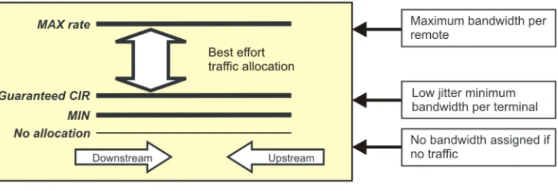
Inroute CIR with Min,
Guaranteed and Max
bandwidth
CIR is the rate that has been committed to a particular remote. Satellite routers are allocated bandwidth based on the following parameters:
1. Minimum CIR Rate 2. Guaranteed CIR Rate 3. Maximum CIR Rate
At the very least, the network operating center (NOC) will try to satisfy the minimum configured rate. In the event that additional bandwidth over the minimum is available it is up to the NOC’s discretion to provide bandwidth for a particular remote. This excess bandwidth is not guaranteed and when available will be capped at the maximum rate.
Configurable Demodulation
System (CDS)
This release is the first release of the next generation return channel (inroute) Configurable Demodulation System (CDS). Advantages of the CDS over its predecessor (IFSS-TC) include:
• Improved configuration flexibility
• Increased inroute capacity per rack space (up to 9 inroutes for 1U of rack)
• Supports higher symbol and user data rates
• Fully managed by NMSS
While the introduction of CDS is an upgrade, HX systems continue to support IFSS-TC, as well.
CACTI Network Manager
CACTI Network Manager (new installations only) provides for network monitoring, event logging, and graphing SNMP statistics. Templates for network devices are included with this feature.Expansion rack option
An expansion rack option has been added to the HX System fixed rack model.The HX System
The HX System is an innovative IP broadband very smallaperture terminal (VSAT) system created by Hughes. The system is designed and optimized for smaller networks that require high-bandwidth, high-quality of service (QoS) links. The HX System leverages the best features and capabilities of the proven Hughes HN broadband VSAT system - with over one million terminals deployed - while providing new features that support high-bandwidth, real-time applications such as telephony trunking, video conferencing, and much more.
The most significant upgrade with the HX 1.2.7 over previous models is the inclusion of the mobility feature. While mobile satellite services at lower satellite frequencies (L-band, in particular) have been available for some time, these services tend to provide lower rates of speed (up to 400 kbps) and tend to be very expensive. With the HX 1.2.7, mobile satellite broadband using higher frequency services, such as Ku-band, now provides more bandwidth at a much lower cost.
The HX System’s advanced bandwidth-management features enable operators to customize fine-grained QoS and SLAs (service level agreements) on a per-satellite router basis. For example, HX System operators can guarantee both inbound and outbound bandwidth per satellite router. In addition, the HX System can provide dynamic bandwidth allocation for
time-division multiple access (TDMA) channels based on usage and need, allowing development of a wide range of service plans fine-tuned to meet individual needs. By leveraging the DVB-S2 transmission standard for the outbound channel, the HX System
achieves the best spectral efficiency of any TDM/TDMA network available today.
The HX network architecture is based on the TDM/TDMA star topology. As shown in Figure 1, the system can provide high-speed Internet protocol satellite connectivity between the corporate headquarters and multiple remote sites. The HX System operates in the Ku, Ka, and C frequency bands.
Note: Although the term satellite router technically refers to all of the equipment at the remote site, it is often used to refer only to the VSAT.
Innovative features
The HX System provides many state-of-the-art features including:• Advanced bandwidth management capabilities – The HX System allows operators to easily provision services like constant bit rate (similar to single channel per carrier or SCPC), minimum committed information rate (CIR) with maximum limits, and best effort services. Plus, the HX System can tailor these service offerings for each satellite router.
• DVB-S2 – The HX System uses DVB-S2—the latest generation satellite transmission standard. In its most basic form, DVB-S2 incorporates 8PSK or QPSK modulation together with low-density parity checking (LDPC). The combination of 8PSK with LDPC produces approximately 30% more bandwidth than DVB-S for the same amount of satellite power/bandwidth.
• Adaptive coding and modulation – The HX System implementation of DVB-S2 supportsadaptive coding and modulation (ACM) in the outbound channel, allowing operators to optimize the outbound channel for each satellite router. For example, satellite routers in low EiRP regions can be assigned robust coding and modulation combinations (QPSK, Rate ½), while satellite routers in beam center can be assigned bandwidth-efficient coding and modulation
combinations (8PSK, Rate 9/10). The application of ACM produces up to 30% more bandwidth than DVB-S2, for a total improvement of up to 60% over DVB-S.
• Most efficient TDMA return channel – Because HX System TDMA return channels use Aloha for initial assignment request, operators can optionally utilize the bandwidth of satellite routers that are idle for some period of time while maintaining the QoS commitment to a customer. The HX System TDMA inbound channel also uses variable length bursts, allowing up to 85% efficiency on the return channel.
• Robust rain fade mitigation techniques – Recognizing that high availability is a crucial element of enterprise SLAs, the HX System provides the industry's most extensive set of features for increasing overall system availability. These features include dynamic ACM on the DVB-S2 outbound carrier, dynamic coding of the TDMA return channel, and dynamic uplink power control for the satellite router.
• Advanced IP features – HX satellite routers support a number of built-in router functions, which are configured remotely at the HX System gateway. These functions
generally eliminate the need for an external router at remote sites. Router functions include flexible addressing with support for routing information protocol (RIP), network address and port translation (NAPT), port forwarding, DHCP service and DHCP relay, DNS caching, and firewall
capability.
• PEP Data acceleration – All HX satellite routers implement the Hughes PEP (performance enhancement proxy for TCP) feature, which includes bidirectional TCP spoofing, data and header compression, IP priority levels, ACK reduction, and message multiplexing.
• Built-in network security – The HX System offers built-in network security as a standard feature. All data transmissions to satellite routers are encrypted to ensure that only
authorized modems access the transmission. Bidirectional encryption is available as an option.
• Adaptive inroute selection (AIS) - A satellite router can select an optimal symbol and coding rate for its inroute transmission as a function of a configured trajectory table and through information it learns about its transmission from a closed loop power control algorithm. See the bulleted description above for Robust rain fade mitigation techniques.
• Cost-effective gateway – The HX gateway is optimized to support small networks. It occupies a small physical space and provides a very cost-effective solution for small networks.
Broadband applications
HX Systems support the following services:• Mobility - HX systems support the use of mobile satellite routers through the use of the following primary enabling technologies:
– Closed Loop Timing – Spreading
– Doppler
• Broadband IP connectivity – The HX System offers a completely private high-speed network with
performance-enhancing features that maximize performance and network efficiency. The performance of individual applications (interactive and file transfer) can be
independently managed with Hughes performance-enhancing proxy parameters.
• GSM backhaul – The HX system can be configured as an IP pipe and used as a global system for mobile communication
(GSM) backhaul to replace T1/E1 and other ground-based base transceiver station-to-base station controller (BTS-to- BSC) network elements.
• IP multicasts – The HX gateway supports IP multicasts to send multimedia or other traffic to multiple remote sites simultaneously, and HX satellite routers include IGMP support to route IP multicast traffic to attached workstations.
• Border Gateway Protocol - BGP is a routing protocol frequently used with MPLS networks. Utilizing BGP, the HX now offers a more seamless interface to the networks.
HX System architecture
The HX system provides star TDM/TDMA connectivityconsisting of a central gateway connecting to multiple HX remote terminals. With a DVB-S/DVB-S2 outbound carrier supporting rates up to 121 Mbps and multiple inbound carriers supporting rates up to 3.2 Mbps, the HX system provides the high throughput needed for high QoS networking.
HX System star topology
The HX system star-topology network has the following major elements, the HX gateway and the HX satellite routers.HX gateway The HX gateway is the central processing center of the network. The gateway provides connectivity between HX satellite routers and customer data centers and/or the Internet.
The HX System supports two types of gateways:
• Fixed gateway
• Transportable gateway Fixed gateway (GW)
The fixed gateway equipment is contained in one or more racks that are in a fixed location.
The majority of this manual refers, by default, to the fixed gateway system.
Transportable gateway (TGW)
The transportable gateway equipment is contained in a single rack that can easily be packed, moved and reassembled.
The system is well suited for applications where network transportability is critical - including homeland security, continuity of operations, tactical military, and remote news gathering. At only two feet in height, the system is a size and
cost-efficient solution to support the rapid deployment of smaller satellite networks in difficult operating conditions.
A TGW overview with a description, list of features, services supported, advantages and technical specifications is included in Appendix B.
HX satellite routers HX satellite routers reside at the end user location and communicate with the HX gateway via satellite link.
Network segments
The HX network is divided into segments, each of whichrepresents a portion of the communications link. These segments include:
• Gateway segment
• Satellite router segment
• Space segment
• Wide area network segment
Gateway segment The gateway is the centralized earth station through which the entire network is controlled. The gateway is normally located at the customer's Network Operations Center (NOC). It contains transmit and receive communications equipment, a radio
frequency terminal (RFT) consisting of RF equipment and a large antenna, and network management subsystems and infrastructure. The gateway segment manages the entire HX System and any backend systems used for handling tasks such as billing, customer care, and provisioning. See Chapter 2 – Subsystems for more information.
Satellite router segment Satellite routers provide broadband TCP/IP communications to remote sites. The satellite router segment is the network segment located at the end-user modems. Each satellite router has an indoor unit (IDU), which contains the receive and transmit units; and an outdoor unit (ODU), which consists of RF equipment and an antenna.
A remote local area network (LAN) host is a device at the remote site that communicates across the HX System via TCP/IP.
See Chapter 9 – Satellite routers, on page 69 for more information.
Space segment The space segment is the satellite portion of the link, and connects all of the satellite routers in the network to the gateway. Wide area network segment The wide area network (WAN) segment includes the Internet and
routers communicate using TCP/IP protocol, including their host computers.
The WAN segment also includes the commercial, off-the-shelf (COTS) switches, routers, and other networking equipment within the gateway that connect the gateway to the independent IP networks.
System management
The network management system server (NMSS), also known as Vision UEM, contains the set of management tools for HX gateway primary components and interface equipment, including:• IP gateway(s) • Satellite gateway(s) • DVB-S2 modulator • Timing subsystem • Inroute components: – DNCC – CDS – Aurora CP
Minor components and equipment are managed through their own interfaces. These components within the NMSS are:
• Element-management server
• Graphical user interface
• Backend database
• CACTI
For more information, see Network Management Support Services (NMSS) subsystem on page 22.
See Chapter 3 – Network management for more information about managing the HX System network.
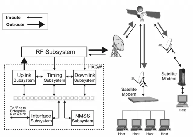
Information flow
Figure 2 illustrates how information flows through the HX System gateway equipment. Note the difference between the arrows used to represent inroutes and those used to represent outroutes. The differing widths of these arrows signify the different bandwidths for data traveling from the HX gateway to (outroutes or uplinks) and from (inroutes or downlinks) the satellite modems.Chapter 2
Subsystems
This chapter describes the subsystems that comprise the HX system. These subsystems are standard with all Hughes systems and are required for network operation.This chapter includes:
• Interface subsystem on page 15
• Radio frequency (RF) subsystem on page 16
• Uplink subsystem on page 16
• Timing subsystem on page 18
• Downlink subsystem on page 19
• Network Management Support Services (NMSS) subsystem
on page 22
• Local area networks on page 25
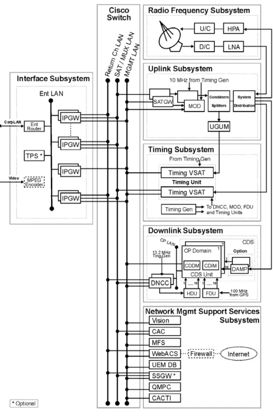
The subsystems and the network connection are illustrated in Figure 3 on page 14.
See Chapter 3 – Network management, on page 27 for a more detailed discussion on Network Management.
Interface subsystem
The interface subsystem includes the IP gateway (corecomponent) and special services gateway (optional component; described in Special Services Gateway (SSGW) Installation, Operation, and Maintenance Manual (1032030-0001).
IP gateways
The IP gateways provides the interface between the HX gateway and the enterprise intranet terrestrial data connections. The IP gateway performs the IP address mapping, packet transmission, compression, and other functions needed to support the HX satellite routers. Traffic between the IP gateway and the intranet host uses a standard IP packet format. However, the IP gateway implements an Hughes-proprietary protocol between itself and the satellite routers that is optimized for efficient, yet reliable communication over the satellite link.To facilitate data transfer from the IP gateway to the satellite gateway, the IP gateway encapsulates unicast and multicast frames containing traffic destined for satellite routers within User Datagram Protocol (UDP) packets. The IP gateway obtains the encryption information from the CAC, then encapsulates and sends the appropriate unicast data and keys information to the satellite gateway where the traffic stream is encrypted.
IP gateways forward the encapsulated unicast and multicast IP traffic from the customer network to the satellite gateway over the satellite LAN for further outroute processing. Unicast traffic is addressed to a specific satellite router; multicast traffic is sent to satellite routers in a pre-defined group and can include
management traffic or user traffic.
The IP gateways record statistics files that contain the amount of traffic that has been processed for each IP subnet. IP gateways are designed as a warm redundant pair with online and standby
modes of operation. IP gateways are SNMP-enabled and are configured, controlled, and monitored by Vision UEM running on the NMSS.
For TCP traffic, the IP gateway implements
performance-enhancing proxy (PEP) features. See Performance Enhancing Proxy (PEP V3) on page 52 for a description of the PEP feature.
The IP gateway functionality also includes support for
multicasting services. In this mode of operation, the IP gateway forwards multicast data (such as multimedia and advertising content) through the satellite gateway to the remote sites that are enabled (using the conditional access system) to receive the multicast stream. Additionally, each IP gateway can also be
configured with a maximum total CIR to limit the IP traffic to the customer's contracted grade of service.
Depending on the size of the network, there may be many IP gateways within a single HX System gateway. Typically, the HX gateway contains at least one IP gateway for each inroute subsystem.
Radio frequency (RF)
subsystem
The RF subsystem performs the actual transmission and reception of satellite signals. The RF subsystem delivers received satellite signals to the inroute subsystems at RF. It takes outroute signals in the DVB asynchronous serial interface (ASI) format and modulates and transmits those signals. The RF subsystem is managed via SNMP using the management LAN and is internally redundant. The RF subsystem consists of the radio frequency terminal (RFT) and the system IF distribution module, which use commercial, off-the-shelf equipment.
Radio frequency terminal
The RFT takes the uplink intermediate frequency (IF) output of the system IF distribution module, upconverts it to radio frequency (RF) and transmits it to the satellite. The RFT also receives from the satellite the RF echo of the transmitted signal, along with the RF input for the inroutes, downconverts the signals to IF and forwards the downconverted signals to the system IF distribution module and then to the downlink subsystem. The RFT is made up of commercial off-the-shelf products.Uplink subsystem
The uplink (or outroute) subsystem performs the multiplexing and transmission of all outbound IP traffic. All outbound traffic is formatted to conform to the DVB-S or DVB-S2 standard. The outroute subsystem is made up of satellite gateways, DVB modulators, and outroute redundancy equipment.Satellite gateway
The satellite gateway (SATGW) receives bundled satellite traffic from the other NOC components over a LAN segment, formats the information into individual packets, and forwards them to the DVB modulator for transmission over the satellite.The satellite gateway receives bundled satellite traffic over the satellite LAN from the following components:
• IP gateways (including management gateways)
• DNCCs
• Timing unit (TU)
• Conditional access controller
(
CAC) serverSatellite gateways can receive encapsulated traffic using multicast addressing.
The maximum length of the packets is configurable for each IP gateway. A maximum expected frame length is also configured into each satellite gateway and must be at least as large as the largest corresponding value configured in the IP gateways feeding that satellite gateway. The UDP frames are all destined to a single IP multicast address. The frames contain sequence numbers and other header information and one or more user traffic frames. Multicast traffic is received over the satellite gateway multicast address. This multicast address is unique across transponders. The conditional access (CA) key traffic is received over the CAC multicast address. This address is common to all satellite
gateways configured in the NOC. The common CAC address and the unique satellite gateway address allow a single LAN
configuration to support multiple transponders. All traffic to the satellite gateway is sent via multicast. The satellite gateway can receive traffic on multiple (a maximum of 8) multicast addresses.
DVB and DVB-S2
modulators
Each satellite gateway connects to a DVB or DVB-S2 modulator. The modulators are paired to satellite gateways and are designed to switch together as a chain in the event of a failure. The DVB modulators provide a 70 MHz IF output that is fed into an outroute redundancy module and then onto the uplink system of the RF terminal.
Two standards are supported, DVB-S and DVB-S2. Modulators can be configured to support DVB-S only or both standards.
• DVB-S supports Reed-Solomon coding and QPSK modulation
• DVB-S2 supports LDPC coding in both QPSK and 8PSK modulation.
The modulator supports the following symbol rates:
• In DVB-S mode, the DVB modulator supports the following symbol rates: 1.25, 2.5, 5, and 10 - 45 Msps, using FEC rates up to 7/8.
• In DVB-S2 mode, the DVB modulator supports symbol rates of 1–45 Msps in 1 Msps increments. The supported FEC rates depend upon the frame length (short codeblock or normal codeblock) and type of modulation:
– Short, QPSK modulation: 1/2, 3/5, 2/3, 3/4, 4/5, 5/6, 8/9 – Short, 8PSK modulation: 3/5, 2/3, 3/4, 5/6, 8/9
– Normal, QPSK modulation: 1/2, 3/5, 2/3, 3/4, 4/5, 5/6, 8/9, 9/10
– Normal, 8PSK modulation: 3/5, 2/3, 3/4, 5/6, 8/9, 9/10 DVB-S2 supports either CCM or ACM mode:
• In CCM mode, all satellite routers in the network operate at the configured modulation rate, symbol rate, and FEC rate.
• With DVB-S2 operating in ACM mode, satellite routers can adapt their FEC coding rate and modulation type (QPSK or 8PSK) to maximize the downlink speeds for the current operating environment.
The DVB modulators are commercial off the shelf (COTS) products.
Outroute redundancy
For the redundant configuration, outroute redundancy isimplemented to switch the SATGW/DVB modulator chain. The functionality of monitoring the outroute and commanding a switchover is implemented by the quality monitor PC (QMPC) software component.
Timing subsystem
The timing subsystem provides the master timing for the entire system. It also maintains the timing synchronization between the NOC and the satellite routers. This subsystem consists of the timing generator, the timing unit and the closed loop timing (CLT) feature.Timing generator
The timing generator provides the reference clock frequencies to several NOC components, including both outroute modulators, the timing unit, the optional automatic cross-polarization (ACP) spectrum analyzers, and the DNCCs. It also generates asuperframe pulse for the DNCCs, the RCDs (older systems), the timing unit, and the radio frequency terminal (RFT).
Timing unit
The timing unit provides return channel timing support for a specific outroute. The timing unit consists of a pair of timing satellite routers, one of which is configured as a superframe numbering packet (SFNP) transmitter. The timing unit also provides timing information for the optional ACP subsystem. A timing unit measures the difference in time between the L-band looped back signal and the signal looped back from the satellite and provides TDMA timing information to the satellite return channel terminals and the DNCCs within the downlink subsystems accessible from terminals receiving this outroute.Closed loop timing
The CLT feature provides timing adjustment feedback to enable the satellite router to transmit as close as possible to the middle of the burst aperture.For more information see Closed loop control on page 65.
Timing subsystem physical
constraints
A timing generator supports:
• Ten 10 MHz coaxial connectors thereby supporting up to 8 DVB modulators or ACP systems. Two per outroute and one per ACP system (if added) are required.
• Eight DNCCs.
• Six timing VSATs.
Downlink subsystem
The HX gateway can be configured with one or more inroutes. Each inroute is a time-division multiple access (TDMA) return channel. The inroute subsystem manages the return channels associated with a group of satellite routers.This system release features the introduction of the CDS, which replaces the IFSS-TC in newer systems.
Configurable Demodulation
Subsystem
The CDS is a powerful digital signal processor that demodulates one or more carriers, performs error corrections, and forwards the resultant bursts to a NOC component.
A CDS consists of a single cardset, configurable demodulation decoder module (CDDM) and configurable demodulation interface module (CDIM). The CDS is hosted on a CompactPCI (cPCI) chassis, along with a host control processor (CP) that is connected to the dynamic network control cluster (DNCC) through a LAN interface. The DNCC interfaces with the NOC components via multiple LANs. The CDS receives inroutes from the RF equipment and timing from the timing components. The inroute bursts are processed by the CDS (demodulated and decoded) and passed on to the DNCC. After converting inroute bursts into IP packets, the DNCC passes the inroute traffic onto the final destination, such as the corporate LAN or the Internet via the internet protocol gateway (IPGW).
The CDS is completely compatible with DNCCs that interface with Aurora return channel CPs.
One CDS platform can handle up to 9 inroutes, which can vary based on whether a type 1 or type 4 board is used, across a frequency band up to 36MHz wide, in a single 1U chassis. The term CDS can refer to one or more instances of the CDS platform.
CDS replaces the IFSS-TC, which shipped with older systems. Furthermore, while the introduction of CDS is an upgrade, HX systems continue to support both CDS and IFSS-TC.
CDDM The CDDM is a 6U wide module that plugs into one of the I/O slots in the front of a cPCI chassis.
CDIM The CDIM is a 6U wide module that plugs into one of the I/O slots in the rear of a cPCI chassis. The CDIM card accepts a wideband IF input signal containing one or more inroutes, centered at 70 MHz with a bandwidth of 36 MHz from the external NOC equipment.
IF Subsystem-Turbo Code
system
In place of the CDS, most older systems have the IFSS-TC. The IF Subsystem-Turbo Code (IFSS-TC) is a modular system that:
• Acts as the HX gateway satellite radio receiver.
• Demodulates and decodes inroute signals received from remote user modems via the satellite.
A typical redundant configuration includes:
• Up to two compact peripheral component interconnect (cPCI) chassis, that contain storage media, power supplies, control processors (CPs), CP transition boards, and RCDs that contain software radio modules (SRMs) and receive control modules (RCMs)
• One optional frequency distribution unit (FDU)
• Up to two intermediate frequency distribution units (IFDUs)
• One optional HNS timing control (HNSTC) distribution unit (HDU)‘
A nonredundant system contains one cPCI chassis.
Return channel components The NOC can be configured with one or more TDMA return channel subsystems (TRCSs). The TRCS manages the return channels associated with a group of satellite modems.
Return channel demodulator
The RCDs provide the demodulation of the TDMA burst return channels. The RCD accepts the inroute data, extracts the traffic data, and gives the traffic data to the DNCC. The RCD consists of the SRM and RCM.
Return channel control processor
The return channel CP is a Pentium III single-board computer in the cPCI chassis that manages the RCDs. Depending on the NOC rack configuration, there may be 1, 2, or 4 CPs in a system. Return channel IF distribution
The return channel IF distribution module receives the IF output from the system IF distribution module and forwards it to the RCDs.
Dynamic network control
cluster (DNCC)
The dynamic network control cluster (DNCC) performs all the processing and control functions of the inroute subsystem. The DNCC manages return channel bandwidth. The DNCC receives traffic bursts and control bursts. The traffic bursts contain modem IP traffic as well as “piggybacked” bandwidth requests. The control bursts can contain modem status, bandwidth requests, or
ranging information. Ranging is used to adjust the operational parameters of a site and to fine-tune the satellite router's timing and transmit power without the need for user intervention. If the DNCC requests that the satellite router enter ranging mode, the satellite router uses its assigned ranging burst. Based upon these measurements, the site chooses the proper settings to transmit traffic to the DNCC.
The DNCC processes each type of burst and constructs IP packets, which are forwarded to the IP gateways. Different bandwidth allocation algorithms are implemented on the DNCC. Additionally, the DNCC generates the frame timing messages and forwards them to the timing components.
The DNCC is simple network management protocol
(SNMP)-enabled and is configured, controlled and monitored by Vision UEM running on the NMSS.
The DNCC maintains detailed logs on all events pertaining to the downlink subsystem. These include ranging/commissioning information, inroute packet statistics, and other relevant data. Redundant HX gateways contain two DNCCs configured as a warm redundant pair with primary (online) and secondary (standby) modes of operation.
Control Processor To maximize efficiency when processing traffic, each inroute defined at the DNCC is assigned an inroute group. All inroutes in the same group are managed by the same CP. The number of inroutes differs between CDS and IFSS-TC (older systems).
Systems with CDS
In newer systems with CDS and one BPE FPGA on the CDDM board, each CP can support the following:
Systems with IFSS-TC
In older systems with IFSS-TC, each CP can support the following:
• 12 inroutes, 256/512 ksps Turbo BCH at 1/2, 2/3, and 4/5 forward error correction (FEC) rate
• 6 inroutes, 1024 ksps Turbo BCH at 1/2 and 4/5 FEC rate
• 3 inroutes, 2048 ksps Turbo BCH at 1/2, 2/3, and 4/5 FEC rate
RCDs are housed in a cPCI chassis. The HX gateway rack can support either one or two cPCI chassis, with three RCDs per chassis. Each RCD can support a single inroute type
(combination of symbol rate, FEC rate, and coding type).
Network Management
Support Services
(NMSS) subsystem
The NMSS is the name given to the functional elements running in the NMSS (network management and support services) server. These elements are:
• Vision - provides configuration and control interface for many of the NOC components
• Conditional Access Controller - provides access control for information transmitted through the HughesNet service
• Management file server (MFS) - provides a repository for software and configuration parameters to be downloaded to NOC components
Table 1: CP support for systems with CDS
Symbol Rate (for all active inroutes)
CDDM Board Type (Number of BPE FPGA's) Maximum active inroutes 256 KSPS 1 9 256 KSPS 4 9 512 KSPS 1 4 512 KSPS 4 9 1024 KSPS 1 2 1024 KSPS 4 9 2048 KSPS 1 1 2048 KSPS 4 4
• Web-based auto-commissioning - provides commissioning services for satellite routers
• UEM database - stores all network configuration data
• Special services gateway - (optional) acts as an IP gateway for satellite routers before they are commissioned, and provides bandwidth broker services for the downlink
• Quality Monitor PC - receives satellite output and monitors the quality
• CACTI - network monitoring and event logging
Vision
Vision provides a software interface to monitor, configure, and control network components, including satellite routers and NOC components.Conditional access
controller
The conditional access scheme prevents the reception of traffic belonging to a different customer. The CAC uses encryption technology to protect the user against unauthorized access. The CAC components perform the key management for the unicast TCP/IP encryption and IP multicast conditional access. Typically a single multicast IP address is used; however, a scaling feature that uses multiple multicast addresses is also available for large networks.
Management file server
The management file server (MFS) is both a repository and a component controller. It is a repository for software downloads and parameter files for managed NOC components. It also controls the enable/disable functions of NOC components and notifies those components of the file and version information and updates.MFS relies on the management gateway client (MGC) service that is installed on each managed component. The MFS sends periodic heartbeat messages to the MGCs on these components using broadcast or multicast. If the MGC on a particular components determines that new software or configuration files are needed, it downloads these files from the MFS using FTP. Vision copies files into MFS using FTP/Windows file sharing and notifies the MFS of any newly uploaded files using SNMP.
Web-based
auto-commissioning
When a satellite router is installed, certain information must be provided to the NOC operator to ensure the site is commissioned properly. Auto-commissioning automates the commissioning process with no intervention by the NOC operator to provide fast turnaround on satellite router installations and prevent
configuration mistakes. WebACS also configures components necessary for older generation equipment.
Auto-commissioning can take place over the Internet or the satellite link using the web-based auto-commissioning server (WebACS).
Satellite-based commissioning Satellite-based commissioning (SBC) is a optional feature that allows an operator to commission the installation without using a phone line to contact the WebACS. This method automatically establishes TCP connectivity between the client and NOC components.
SBC implements various approaches to enable this to occur. Some of the important techniques used to enable this are as follows:
• The source IP address configured in the TCP/IP stack can be the same for multiple PC's that are commissioning
simultaneously
• The default gateway IP address for all commissioning PC's will be the same
• The DNS server IP address can be any private address reserved by HNS since DNS lookups are proxied in the NOC during SBC
The SSGW is the major NOC component of the SBC process. SBC is not available with the TGW-100.
UEM database
The unified element management (UEM) database contains configuration information for these services, maintained under a separate schema for each. The NOC Forms application provides a configuration interface for CAC, WebACS, while Vision contains its own interface. The MFS is configured using an ASCII text file.Special services gateway
The special services gateway acts as the IP gateway for satellite routers that are not yet commissioned. The special services gateway is optional, but required for using the WebACS feature. The SSGW is not an option on the Transportable Gateway (TGW) model.Quality monitor PC
The QMPC, with help from the SNMP interface, receives the satellite gateways modulated output and monitors its quality, posting alarms and initiating satellite gateway switchover as appropriate.Used in redundant systems only, the QMPC ensures that only one SATGW-DVB modulator chain passes traffic at any given time. The SATGW-DVB modulator chain to pass traffic can also be selected manually by the HX gateway operator.
The QMPC resides on the NMSS server and has the ability of supporting multiple transponders (up to eight outroutes).
CACTI Network Manager
CACTI Network Manager (new installations only) provides for network monitoring, event logging, and graphing SNMP statistics. Templates for network devices are included with this feature.Local area networks
The HX systems use LANs and VLANs to simplify connections and reduce cable clutter. The following list indicates the functions of the individual LANs/VLANs within the system.• Gateway LAN
– Management VLAN – Satellite or MUX VLAN – Return channel VLAN
– Control processor (CP) VLAN
• Enterprise LAN/VLAN
Gateway LAN
The gateway LAN is used for internal communications and consists of four VLANs.Management VLAN The management LAN connects the network management subsystem to other subsystems.
The management LAN carries all NOC administrative messages, including managed NOC component software and configuration information.
Satellite VLAN The satellite LAN connects the multicast broadcasters to the multiplex (MUX) subsystem.
The satellite LAN carries outroute traffic destined for satellite routers from the IP gateway, management gateway, dynamic network control cluster (DNCC), timing unit, and conditional access controller (CAC).
The satellite gateway receives the traffic on the satellite LAN and sends it on the outroute. The satellite also sends flow control information to all the IP gateways on the satellite LAN.
The satellite LAN is a dedicated LAN, which makes it easier to troubleshoot in cases of packet loss.
Note: The nonredundant HX system configuration does not contain a QMPC.
The Satellite LAN is also referred to as the Multicast or MUX LAN.
Return Channel LAN The return channel LAN allows the DNCC to forward received inroute packets to the IP gateways in the uplink subsystem. The DNCC transmits these packets into the return channel LAN. CP VLAN The CP LAN carries inroute control messages, such as burst time
plans, from the DNCC to the CDS (or the IFSS-TC). It also carries user traffic from the CDS (or the IFSS-TC) to the DNCC.
Enterprise LAN/VLAN
The enterprise LAN carries user and management traffic from the IP gateways to the customer’s enterprise router or the internet. The enterprise LANs connect an uplink subsystem to the independent IP network accessible by terminals receiving the subsystem's uplink in such a way that the traffic from one independent IP network is accessible only by a terminalauthorized to access that network. The downlink subsystem also requires access to these enterprise LANs so that it can forward inroute packets to the associated equipment within the
appropriate uplink subsystem.
Chapter 3
Network management
This chapter describes the network management functions.• Overview on page 27
• Configuration management on page 29
• Fault management on page 31
• Performance management on page 32
• Security management on page 32
• Component control on page 34
Overview
Network management provides management tools for HX Systemgateway components and interface equipment, including:
• IP gateway • Timing unit(s) • Satellite gateway • DVB modulator • DNCC • CP
• CDS (or IFSS-TC in older systems)
All other network components and equipment are managed through their own interfaces.
Figure 4 illustrates the network management system architecture and how it connects to other HX gateway components.
NMSS server components
The HX gateway incorporates four major network-management components within a single high-performance server:• Element-management server
• Graphical user interface (GUI)
• Back end database
• CACTI
These components enable the HX gateway operator to perform both network operations (such as monitoring network status and statistics) and overall network management activities (such as configuration and control).
Configuration
management
NMSS configures satellite routers and some of the HX gateway components. The network configuration is stored in the UEM database, and operators can maintain it either through the Vision graphical user interface (GUI) or provision components using a batch mode facility. In addition, Vision provides a commissioning interface to the Web-based auto commissioning system
(WebACS) to support the auto-commissioning of satellite routers.
Gateway component
configuration
NMSS generates configuration files for each Vision-managed gateway component as needed, and sends them to the MFS component of the NMSS server. The MFS acts as a central repository for all configuration and software files for
Vision-managed gateway components. Each gateway component managed by Vision contains a management gateway client
(MGC). MGC is in constant communication with MFS using a proprietary protocol. the MGC downloads configuration files from MFS.
Remote site component
configuration
NMSS also generates configuration files for remote site
components. It communicates with remote components through a specialized mechanism called software download (SDL), which informs the components of changes in required files. The SDL protocol permits files to be delivered in both push (sent unilaterally by NMSS) and pull (requested explicitly by the modem component) modes. In addition, NMSS uses a multicast delivery mechanism to transmit shared files simultaneously to all modem components that need them, thereby conserving outroute bandwidth. Files that are not shared between components are sent via unicast delivery.
Profiles and profile groups
To simplify the task of managing the many differentconfiguration parameters available in the HX System, NMSS provides conceptual groupings of related parameters called
profiles. Profiles are generally organized by function or feature, and can be of two types: shared and unique.
• Shared profiles can contain such parameters as resource allocations and tuning parameters, which are often shareable. Operators can create shared profiles and manage them independently of any particular network component.
• Unique profiles contain parameters, such as interface addresses, whose values cannot be shared because they must be specific to a component.
Most shared profiles are optional profiles. Profiles containing parameters that must be configured on a device are considered
mandatory profiles. Profiles containing critical values that should be changed only by a network administrator are considered
restricted profiles. A network administrator can determine which profile types are considered restricted.
Because the large number of optional features can make even the management of profiles tedious, NMSS provides an even higher level of conceptual grouping called the profile group. A profile group is simply a collection of shared profiles that can be associated with a component as a set. A remote site component can be associated with one core profile group, which is assigned by a network administrator, and optional customer profile groups, which can contain profiles that are not restricted.
Software configuration
management
NMSS supports the ability to remotely install and upgrade software images on both gateway and remote site components. Software profiles are used to manage software versions. Vision distributes software files to gateway and modem components using the same mechanisms used to distribute configuration files. Software images for modem components are multicast via SDL.
Configuration interfaces
NMSS provides a number of interfaces through which network configuration can be defined and maintained.The NMSS graphical user interface (GUI) is the interactive interface that operators use to perform initial network definition and the creation of profiles, users, and hub components, as well as other administrative tasks. The GUI provides full manual control of all configuration parameters and system settings, subject to configured operator access policies and restrictions. HX gateway personnel can use the GUI, as can customers at remote sites and customer support agents.
NMSS also has a provisioning interface intended for batch-mode definitions of remote site components. The provisioning tool extracts a list of sites to be provisioned from an extensible
markup language (XML) formatted file and updates the Vision UEM database with the site definitions and configurations. A typical use of this tool is the integration of a service provider's order-entry system. For better integration with desktop tools, there is also a utility to convert comma-separated value (CSV)-formatted files into XML.
Finally, NMSS provides a commissioning interface that is used by the WebACS during the auto-commissioning process.
Fault management
Fault management functions provided by NMSS include status monitoring, reporting, and alarms.Status monitoring
Vision monitors the status of gateway and remote site network components through simple network management protocol (SNMP) and proprietary Hughes protocols. All managed HX network components have embedded SNMP agents that can report status and statistics information to a suitably configured SNMP manager.Vision uses SNMP to periodically obtain key status information from gateway components. It can also query remote site
components periodically for key status information, although this capability can be disabled to conserve network resources. Vision can use an alternate mechanism–the VSAT information protocol (VIP)–when available, to get status information from remote sites more efficiently.
Current status information is displayed on the Vision UEM GUI through color-coded icons. The GUI also provides fault-isolation capabilities that operators and customer support agents can use to troubleshoot and diagnose faults. The diagnosis functions use real-time SNMP queries to report up-to-date information from network components.
Alarms
HX network components with SNMP agents generate SNMP traps when certain error conditions occur, and send them to a configurable trap IP address. The traps generated by network components are documented in the SNMP management information base (MIB) definitions for those components. To assist in the detection of failed sites or specific patterns of network failures, NMSS can generate certain alarms in the form of SNMP traps. For example, a component alarm can begenerated when a remote site has been down for a configured period of time, and an aggregate alarm can be generated when the number or rate of failures of components in a specific group exceeds a configured threshold.
Performance
management
NMSS provides both real-time and historical statistics on network components and traffic. These statistics are obtained by querying components through SNMP.
Real-time statistics
Real-time performance reports are shown through the Vision UEM GUI. Detailed statistics, which are updated periodically, can be displayed on every managed network component. The display formats can be changed dynamically to show absolute values, relative values, deltas, or rates. NMSS also has an integrated graphing tool called FlexGraph that can be used to build an ad hoc graph of selected statistics to display trends in real time.Historical statistics
The historical statistics collection feature enables users to define ad hoc sets of statistics to be sampled periodically and saved in a disk file. NMSS can run the sampling operations between a specific range of times, and save the results in a comma-separated variables (CSV) formatted file. This facility can be used for long-term trend analysis.Security management
NMSS provides mechanisms for operator security, network component security, and encryption key management.Operator security
NMSS controls all access to network management features by user-level authentication. All interfaces, whether interactive, batch-mode or programmatic, are protected by a user id/password login sequence.There are two classes of users defined. Privileged users have unrestricted rights. They can define other users, assign access rights for those users, and perform other supervisory and administrative functions. Unprivileged users can only perform actions for which access rights have been granted to them.
Network component
security
The network is logically partitioned into network management domains (NMDs):
• Configuration NMDs
• Management NMDs
Each operator can be associated with one or more NMDs, thus restricting that operator’s access to network devices only in the assigned NMDs.
Configuration NMDs Vision supports logical partitioning of the network into non-overlapping domains called configuration NMDs.
Partitioning is performed at the network device (satellite router or HX gateway component) level.
When a network is installed, one NMD, called the default NMD, is automatically provided. Each device belongs to exactly one NMD.
Management NMDs To limit the number of service offerings that must be managed and maintained, all value-added resellers (VARs) are presented with the same set of service offerings (and therefore, profile groups). Because profile groups are linked to NMDs, all satellite routers belonging to VARs must reside in the same NMD in the NMSS.
To allow each individual VAR to monitor and control its own satellite routers, yet prevent them from accessing other VAR’s satellite routers, NMSS provides a management NMDthat may be assigned to each satellite router. Operators can then be assigned to a management NMD.
Management NMDs differ from configuration NMDs in three important aspects:
• A management NMD is optional for a satellite router.
• Any operator assigned to a management NMD may ONLY be granted monitor and control privileges to those satellite routers within the management NMD.
• No configuration privileges may be granted to any operator within a management NMD.
Encryption key
management
The management of traffic encryption keys is performed by the UEM/CAC. See For more information, see Chapter 4 – Network security.
Component control
NMSS can send commands to network components using SNMP for actions such as resets, reboots, and forced reloads of software configuration.HX gateway control
You can send commands to the following HX gateway components:• IP gateway (IPGW) / satellite gateway (SATGW)
• MFS (resides on the NMSS server)
• DNCC
• CP
• CDS
Chapter 4
Network security
This chapter describes the data security features in the HX System. These features guarantee data integrity and confidentiality, and protect the network from intrusion and external exploits. The following topics are presented:• Data encryption on page 35
• Network security features on page 36
Data encryption
The HX System can employ several information assurance techniques to safeguard the integrity and confidentiality of data transported through the system. These techniques include:• DES-encrypted outbound channel
• Two-way IPSec encryption
DES-encrypted outbound
channel
The outbound channel is encrypted using the data encryption standard (DES) by the HX CAS (conditional access system) feature. This CAS feature:
• Is hardware-based
• Ensures that traffic is received by satellite routers legally
• Prevents unauthorized eavesdropping
The HX CAS feature assigns a unique key to each satellite router. It is responsible for key management and for encrypting
outbound data to satellite routers to ensure that satellite routers can only decrypt the data intended for them.
When a satellite router is commissioned, it requests its encrypted effective master key (EEMK) from the HX gateway. This key is sent to the satellite router, and then:
• Used at the HX gateway to encrypt all data sent to the satellite router
• Used by the satellite router to decrypt all data received from the HX gateway
Because all data transmissions to satellite routers are uniquely keyed, a satellite router can decrypt only the data sent to it. The EEMK is also used by satellite routers to authenticate themselves to the HX gateway.
Two-way IPSec encryption
IPSec in the HX System is NIST for FIPS 140-2 level 1 certified and has these characteristics:• End-to-end encryption from satellite router to the endpoint on the enterprise network using IPSec, Advanced encryption standard (AES), and Internet key exchange (IKE) protocols
• Rides over top of the encrypted outroute and clear inroutes
• AES implemented in software
• TCP proxy is outside of the IPSec tunnel, preserving satellite acceleration in a secure configuration
The HX System provides standards-based IPSec/IKE support for encrypting user data traffic and managing encryption keys. The IKE protocol is used to automatically generate and maintain 128-bit session keys and to set up an IPSec tunnel between a satellite router and an IP gateway in the enterprise network. This ensures that the data is encrypted end-to-end between the customer's remote site and the enterprise network.
The HX System IPSec feature provides encryption without affecting the TCP acceleration and prioritization features. (See
Network layer features on page 51 for information about the TCP acceleration and prioritization features.) The Hughes IPSec Kernel is NIST certified.
Network security
features
The HX System provides the following network safeguards to protect the HX gateway and the LANs connected to satellite routers:
• Firewalling – A packet filtering firewall to protect LANs connected to satellite routers
• Fenced Internet – URL white lists can be defined to restrict web browsing from remote LANs to only permitted sites, IP addresses, and domains.
Firewalling
Satellite routers have an embedded firewall. Firewall rules can be defined in satellite router profiles at the HX gateway andforwarded to satellite routers. There are also firewall
configuration and statistics web pages on the HX satellite router System Control Center which, when enabled in HX gateway profiles, can be used to create firewall rules at the satellite router, and view firewall statistics. The HX satellite router firewall works
Note: The HX system supports network address translation (NAT) and port address translation (PAT)—features that can hide the topology of LANs behind a satellite router to prevent
computers on those LANs from being directly addressed from the Internet. See NAT/PAT on page 53 for information about this feature
Fenced Internet
The fenced Internet access (FIA) service is an option that requires a TurboPage server. The FIA service provides a mechanism for enterprise customers to restrict remote site access to a limited number of specifically approved Internet sites. Different lists of approved sites can also be supported for multiple subsets of a customer's remote sites.Chapter 5
Bandwidth management
Bandwidth management is the collection of techniques used in the HX system to manage available bandwidth to the greatest advantage. The HX system uses a variety of techniques to manage bandwidth to maximize flexibility and adapt to environmental conditions while providing guaranteed levels of throughput to meet service level agreements (SLAs) or demanding real-time media transport requirements.The following sections describe the bandwidth management techniques used in the HX system:
• Bandwidth management overview on page 39
• Inroute bandwidth pooling on page 40
• Advanced bandwidth management techniques on page 43
• Traffic prioritization on page 47
• Unlimited combination of service plans on page 49
Bandwidth management
overview
The HX System allows operators to customize bandwidth assignments for each satellite router to meet individual QoS and SLA requirements (as compared with the HN System that is designed to provide a fair distribution of bandwidth across a broad set of satellite routers within a collective system). Additionally, the HX System uses variable burst length
transmissions for the inbound route. This is an advantage over systems that use fixed burst length sizes. Such systems waste a significant amount of bandwidth because every inbound burst must be the same size, regardless of actual payload demands. The Hughes HX System allows the return channel burst size to be built optimally per satellite router, based on demand.
Extensive and repeated tests on the throughput of the Hughes inbound system demonstrate inbound efficiency up to 85 percent. In practical application, this means that the aggregate upstream performance for a typical inroute easily reaches 85 percent of the inbound channel rate; for example 1.3 Mbps aggregate upstream throughput for a 1.6 Mbps return channel.
Bandwidth assignments
The HX System has the flexibility to provide two types of bandwidth assignments:• Nailed-up bandwidth - ensures that the bandwidth is guaranteed and has low latency on start-up, but inefficient use of the bandwidth may be experienced if the satellite router is idle for long periods of time.
• Activity-based