by IAN WATSON and JOHN GURD
University of Manchester Manchester, England
INTRODUCTION
Computer users in many areas of scientific study appear to have an almost insatiable desire for processing power. Many of the computations exhibit a high degree of parallelism which is not exploited in conventional computer structures. Considerable interest has been shown in parallel computer architectures in the last decade in order to make use of this property.
The two main approaches toward this goal have become known as SIMD (array processor) and MIMD (multiproces-sor) architectures which are typified by the ILLIAC IV and the C.mmp systems respectively. It is not appropriate to describe these architectures in detail here, but it should be noted that a number of inadequacies have come to light as these systems have been applied to many problems. There are two basic difficulties which appear in both architectures in slightly different guises. The first concerns the arbitrary choice of a fixed number of processing units in an architec-ture (64 in the case of ILL lAC IV, 16 in the case ofC.mmp). The difficulty that is occasioned by this choice derives from the fact that it is often inconvenient, if not impossible, to organize the problem to be solved so that it is exactly the "width" of the architecture. The second problem arises when sections of essentially serial programs are processed. The problems in SIMD architecture are clear; in MIMD systems the difficulty usually appears when a critical area of memory becomes "locked-out" while many processors are trying to access it. Evidence is accumulating that rela-tively little of the potential speedup of SIMD and MIMD systems can actually be achieved for a broad spectrum of problems: Minsky's conjecture, 1 Flynn's analysis2 and
En-slow's view of operating system overheads in multiproces-sors3 all attest to this opinion.
More recently, interest has arisen in data driven compu-tation for the expression of programs (known as Data Flow). A computation is expressed as a data dependent directed graph with nodes representing computational operations and the arcs representing the flow of data. The nodes become ready for execution when all their input data are available. The expression of parallelism in terms of data dependencies rather than in spite of them, leads to a far more natural and flexible picture of parallel program execution.
The theoretical basis of data driven computation can be traced to the paper of Karp and Miller in 1966.4 An extension
of this line into machine architecture was pioneered by the team led by J. B. Dennis at MIT. 5,6
The architecture described in this paper follows the same broad principles as the MIT work but introduces the concept of token labelling as a mechanism to support re-entrant code structures. It is believed that this leads to a more efficient use of storage resources and provides a greater potential for the utilization of parallelism. Another important aspect of the design is the use of pseudo-associative store to perform token matching; this is achieved by reducing the nodes to a simple machine instruction level with a maximum of two inputs.
DATA FLOW PRINCIPLES
In order to illustrate the principles of a directed graph representation, consider the 'Butterfly' of a Fast Fourier Transform shown in Figure 1. The expressions being eval-uated are:
A'=A+C Cos a+D Sin a
B/=B-C Sin a+D Cos a
C'=A-C Cos a-D Sin a
D'=B-D Cos a+C Sin a
These can be built up from six simple nodes performing the functions of addition, subtraction, multiplication, sine, cos-ine and duplication of a value. A node becomes executable when its input values (normally called tokens) are available. Following this principle it can be seen that, assuming at least four execution units, the computation can be performed in seven steps as indicated by the number adjacent to the nodes. The total number of nodes in the graph is 2 t and therefore the computation has an average parallelism of three.
The graph shown uses only simple operational nodes. In order to specify a more comprehensive computational model it is necessary to introduce a much wider set of primitives which provide control functions such as conditional
branch-A B
c
0(o
Figure I-Graph of an F.F.T. Butterfly.
ing. A complete description of a practical order code is beyond the scope of this paper but can be found in other literature. 7
PROBLEMS OF RE-ENTRANCY
A complete Fast Fourier Transform is an iterative com-putation performed on a large array structure. Ignoring, for the moment, practical implementation mechanisms, con-sider the problems associated with using the graph of Figure
1 as a complete description of the arithmetic computation. The input values are not simple scalars but arrays of the form A[l] ... A[N], B[l] .. B[N], etc., for each iteration. In a flexible parallel machine, there is no reason why further iteration steps may not proceed even though one iteration has not been completed for all points in an array. The inputs to the graph can then be of the general form A[n]j, B[n]j, etc., where n represents the array index and i the iteration level. It is then no longer possible to declare a node exe-cutable by the presence of any two tokens on its input as they may belong to totally different parts of the computation.
There are three possible solutions to this problem: 1. The use of a re-entrant graph is prohibited; each point
of the array and each stage of the iteration must be described by a separate graph.
2.
The use of the graph is limited by allowing one token to reside on an arc of the graph at anyone time. This can be achieved by only allowing a node to become executable when both its input tokens are present and no token exists on jt~ output arc.3. The tokens are assumed to carry with them their index and iteration level as a labeL The rules are extended to require two tokens with the same label before a node can be declared executable.
The first mechanism may require large amounts of code storage and, in problems where the iteration depth is only known at run time, the necessity for dynamic code genera-tion. It is believed that this could be a significant overhead in a practical system. The second implies a sequential but pipeIined use of the code. This will severely reduce the exploitation of potential parallelism.
The labelling method permits the use of pure static code and enables maximum usage of any parallelism which exists in the problem specification, This is dearly at the expense of the extra information which needs to be carried by each token.
Assuming that it is desirable to utilize the maximum amount of parallelism available, then the limitation of one token per arc must be rejected in the general case. Of the remaining two methods, it is our contention that token la-belling will result in much lower overheads in a practical system.
One major use of re-entrant code, that of the procedure, has not yet been mentioned. Parallel invocation of proce-dures can be supported by ensuring that a unique identifier is allocated to each input token at the procedure call.
It is not possible in this paper to describe all the impli-cations of token labelling. Techniques are required to sup-port nested iterations, recursive procedure calls and index manipulation in data structures. These can be achieved by nodes which operate on the label fields of tokens rather than the data values. More comprehensive information on the labelling concept can be found in descriptions of our own work7 and that of Arvind and Gostelow at the University of
Irvine, California, U.S.A. 8
THE MACHINE ARCHITECTURE
Although it may be profitable to use a Data Flow com-putational model to describe parallel activities in a wide range of architectures, it is likely that a hardware structure which reflects the model directly will result in the most efficient implementation.
The basic elements of a Data Flow machine must contain parallel processing units which perform the nodal opera-tions, a stored description of the directed graph and a mech-anism for collecting and matching tokens. The first two requirements can be realized using standard processing and storage techniques; the matching operation is more complex. During a computation, tokens will be produced by pro-cessing units which must await the arrival of other Lukens with identical labels which are directed to the same node.
They can then form an executable package to be allocated to a free processing unit. This storage and matching function can be simplified greatly if the maximum number of node inputs is limited to two; an associative storage technique can then be used.
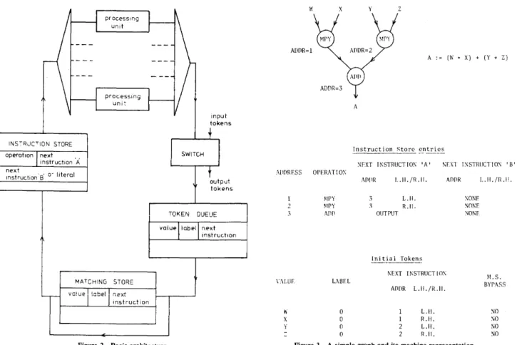
Figure 2 shows the basic architecture of the Manchester Data Flow Prototype which uses these principles.
The Instruction Store is a random access memory which holds the directed graph description. Each entry is in the form of a nodal operation and the addresses of the subse-quent nodes to which the output token(s) will be directed. Note that in this practical implementation, nodes are able to specify two output destinations for their result. It is also possible to specify a literal value as one input to the node. The processing units are microprogrammed microproces-sors with a distribution and arbitration system. The distri-bution system, on receipt of an executable package, will select any processor which is free and allocate the nodal operation. The arbitration system controls the output of tokens from the processors.
The switch provides input and output for the system. Initial tokens are directed to the starting nodes of the com-putation. A special destination address in the final nodes of the graph allows tokens to be output.
The Token Queue is a First In First Out buffer which equalizes data rates around the system.
INSTRJCTION STORE operation next instruction 'A next , Instruction 'B' 0-literal input tokens output tokens TOKEN QUEUE value label next
instruction
Figure 2-Basic architecture.
The Matching Store is associative in nature, although it is implemented using conventional random access store with hardware hashing techniques. The associative field is formed from a concatenation of the label and next instruction fields; the value field is the token value. There is a requirement in a practical instruction set for single input nodes which re-quire no matching operation. A control digit in the next instruction information allows a bypass of the Matching Store in this case.
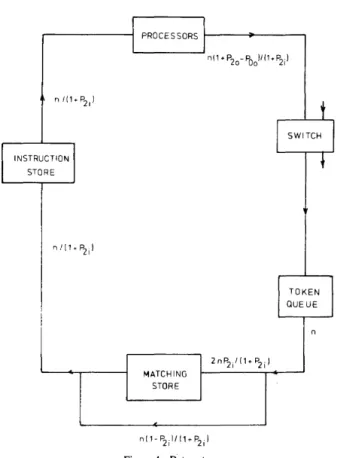
In order to execute a program, the graph description is entered in the instruction store. The initial data tokens are input to the Token queue via the switch. As an example of this, Figure 3 shows a very simple graph to form the sum of the product of two pairs of numbers, together with an indi-cation of the Instruction Store entries and initial token for-mats. The label is not used in this case and is thus set to zero.
The tokens, on reaching the front of the Token Queue, can access or bypass the Matching Store dependent on the Next Instruction Information. An access to the Matching Store will cause an associative search of the store. If a token is found with the same label and Instruction Address it is removed to form a token pair. If no match is found, the incoming token is written to the store.
Token pairs from the Matching Store, or single tokens which have bypassed it, now access the Instruction Store
ADDR=l AllDRESS Ul.lJr \'i y x OPERATlO:\ ~IPY MPY Ann LABH 0 0 0 0 y A . - (1\' * X) + (Y * Z) A
Instruction Store entries
~rXT I~STRUCTIO~ 'A' ~rXT TSSTm~TIOS 'B'
AnllR L, II. /R .11. OUTPUT L.II. R,II. Initial Tokens -~rXT I I\STRUCT 1m,: ADDR L.II./R.II. L.II. R.Il. L.II. rul. AnDR :\ONE ~Ol\r 'Jo~r l.. II. /R .lI. M.S. BYPASS ~O ~O ~O ~O Figure 3-A simple graph and its machine representation.
and form an executable package. This is distributed to any free processor for execution. Tokens produced by the pro-cessors are entered on the back of the Token Queue via the Arbitration Unit and Switch.
This operation proceeds in a pipelined manner around the ring structure until the computation is complete and any output tokens have been produced. Each unit communicates with its successor and predecessor by a two-way handshake interface. This ensures that if, for example, all processing units are busy, the ring operation is suspended until the necessary resources become available.
In order to facilitate the description of the architecture, certain simplifications have been made. It does, however, contain the underlying principles of the prototype Manches-ter Data Flow machine.
IMPLEMENTATION OF THE MACHINE UNITS The token queue
The Token Queue is implemented using Random Access Memory with pointers indicating the front and back of the queue. The store is divided into two independent stacks which permit concurrent read and write operations. Al-though it is not intended to include storage hierarchies in the prototype design, it is felt that use could be made of shift register devices if a much larger queue were required.
The matching store
The pseudo-Content Addressable Memory required for the matching operation uses hardware parallel hashing tech-niques similar to those described by Goto and Ida. 9,10
How-ever, as the order of propagation of results around the ring is unimportant, use can be made of an overflow hashing mechanism rather than a re-hash. The advantage of this is that the average store access time can be reduced and a backing store structure can be introduced.
The instruction store
No special techniques are necessary in the Instruction Store. It is simply a linear Random Access Memory which is addressable by the Next Instruction Information field.
The processing units
Ten Processing Units are constructed from Schottky 'bit-slice' microprocessor elements. They contain alterable mi-croprogram store in order that the instruction set can be changed with ease. All processors are connected to a com-mon bus with a distribution mechanism to allocate execut-able instructions to free processors and allow the output of results. A preliminary study of arithmetic operations has indicated that an average instruction execution time of 3~S can be achieved in each processor.ll
r---11
PROCESSORSI~-~---.
nl1 + P2o- POo)/(1+P2i)I
INSTRUCTIONI
STORE MATCHING STORE n(1-P 2iJ/(1+P2i)Figure 4-Data rates.
t
SWITCHI
~ TOKEN1
QUEUE SYSTEM PERFORMANCEThe processor speed has already been stated as an average instruction time of 3/-tS. If all ten processors can be utilized fully then an instruction execution rate of 3.3 MIPS can be achieved. It is necessary to estimate the storage speeds which are consistent with this.
With reference to Figure 4 we define four values: Tokens per unit time read from the token queue. Probability of an instruction requiring two inputs. Probability of an instruction producing two out-puts.
Probability of an instruction producing zero out-puts.
The following relationships can be derived:
Tokens will access the match-ing store.
Tokens will bypass the match-ing store.
Pairs of tokens will exit from the matching store.
Instruction accesses will be made, and executable instruc-tions formed.
Tokens will be produced by the processors, pass through the Switch, and be written to the token queue.
The constraint imposed by the processing unit is that:
nJ(1 + P21)=3.3x 10⁶
For a typical program it appears, from simulation experi-ence, that the following values of the probabilities are real-istic for typical problems.
U sing these we see that:
P~=0.5 P2o=0.6 POo =0.1
n=3.3x 106x 1.5=4.95x 10⁶
From this we can derive the following required operation times for the units:
1. Token Queue Read-Given by 1/n=202nS.
2. Matching Store Access-A token reaching the match-ing store, requires one read cycle plus one write cycle whether or not it is a successful match. Therefore the times are given by
Read time + Write time=(1 + P2)12nP2i
=303nS
3. Instruction Store Read-Given by (1 + P21)/n=303nS 4. Switch Operation-Given by (1 + P ~)/n( 1+ P 20 - P
oJ
=202nS
5. Token Queue Write-Same as Switch Operation=202nS From these figures it can be seen that the storage units must have access times of the order of 200nS to maintain the execution rate of ten processors. This speed can be readily achieved by low cost MOS storage devices currently avail-able.
ARCHITECTURAL EXPANSION
In order to obtain very high speeds from any parallel computer system it is neceSSqry to exploit parallelism in processing, storage and information transfer. The critical "bottlenecks," particularly in MIMD machines usually ap-pear in the form of crossbar switches, common highways or common stores through which all the processors in the sys-tem may wish to communicate. The reason for this can be traced to the need for a processor to demand, and require rapidly, data from any other part of the system. In addition, there is a necessity to control access to data which has yet to be formed; this can also introduce significant communi-cation overheads.
In a data driven environment, a processor is not required
to perform a section of a computation until all the data are presented to it as an executable package. Rapid data access to other parts of the system and access control are then
unnec~ssary. This suggests an architecture containing a mechanism which accepts tokens from all processors and then distributes them to parallel but independent storage and processing resources.
In the Manchester architecture, this can be achieved by extending the input/output switch to become the intersection point of many identical "rings." A strategy is adopted, using the label and instruction address fields, which distributes tokens from different parts of the computation across the parallel rings.
The switch could be a crossbar, but this would suffer from the same problems as in a MIMD machine. Due to the pipelined nature of the rings, the requirement is for a high throughput rate rather than a fast transfer across the switch. A parallel pipelined structure can therefore be used which does not create a "bottleneck" in the system. The prototype will only contain a single "ring" as described previously. The switch will be constructed to enable the connection of further identical rings at a later date.
A more comprehensive description of the implementation and estimated performance of the multi-ring architecture can be found in other literature. 7
PROGRAMMING A DATA FLOW MACHINE
This section is intended to provide a brief outline of the methods available for programming a Data Flow machine. It would seem that the natural way of expressing a di-rected graph would be via a graphical language, and such languages have been investigated. 12 However, textual lan-guages are far more familiar and it can be argued that fea-tures such as data strucfea-tures are easier to express into a textual form.
One approach is to take a conventional language and translate it into a Data Flow graph. The principles involved in such a translation were originally suggested by Miller and Rutledge. 13 More recently, Whitelock 14 has developed an experimental compiler for a subset of PASCAL which com-piles code for the Manchester machine.
Another class of languages, the Single Assignment Lan-guages, are more naturally suited to the expression of par-allelism in a Data Flow form. Some of these languages, for example Id,15 TDFLi6 and LAPSE,17 have been deveioped specifically for this purpose. Other similar languages such as LUCID18 have developed independently with emphasis on the proof of correctness of programs.
It is too early to forecast with certainty which of these approaches will be most fruitful. The Manchester single assignment and conventional compilers produce code for an architecture simulator; they are being evaluated at the pres-ent time.
It is certain that a Data Flow machine can be programmed without great difficulty, with no requirement for a knowl-edge of the underlying architecture which support,s the
ex-ecution. The exact form of languages which will gain ac-ceptance is yet to be decided.
CONCLUSIONS
The expression of computations in data dependent graph-ical form provides a natural method of determining the par-allelism which is present. In the design of practical execution mechanisms, problems exist in the implementation of re-entrant code. An architecture has been proposed which at-tempts to overcome many of these problems by introducing a label which is carried by every data token. This, together with a pseudo-associative token matching store, results in an architecture which can be constructed at low cost using components which are readily available.
A prototype machine is in the process of design and its performance is being evaluated by simulation. It is not in-tended that this prototype should be of very high speed but should provide a research vehicle for studies of the potential of Data Flow machines for the solution of real problems. The architecture is extensible by using copies of the basic design and this will proceed if the initial investigations are successful.
No attempt has been made in this paper to address the problems of programming a Data Flow machine. Research is, however, being conducted both at Manchester and many other places which promises to produce high-level languages which will allow a machine independent formulation of par-allel programs.
REFERENCES
1. Minsky, M. and S. Papert. "On Some Associative, Parallel and Analog Computations," Associath'e Information Techniques (E. J. Jacks, ed.), Elsevier, 1971.
2. Flynn, M. J., "Some Computer Organizations and their Effectiveness," I.E.E.E. Transactions on Computers, Vol. C-21, No.9, September 1972, p.948.
3. Enslow, P. H., "Multiprocessor Organization-A Survey," A.C.M. Computing Surveys, Vol. 9, No. I, March 1977, p. 103.
4. Karp, R. M. and R. E. Miller, "Properties of a Model for Parallel Com-putations: Determinacy, Termination, Queueing," SIAM J. Applied Mathematics, Vol. 14, November 1966, pp. 1390-14]].
5. Dennis, J. B. and D. P. Misunas, "A Preliminary Architecture for a Basic Data Flow Processor," Proc. 2nd Ann. I.E.E.E. Symposium on Computer Architecture, January 1974, p. ]26.
6. Dennis, J. B., D. P. Misunas and C. K. Leung, "A Highly Parallel Processor Using a Data Flow Machine Language," CSG Memo 134, Laboratory for Computer Science, M.I.T., January ]977.
7. Gurd, J. R., I. Watson and J. R. W. Glauert, "A Multilayered Data Flow Computer Architecture," Internal Report, Development of Computer Science, University of Manchester, February 1978.
8. Arvind and K. P. GosteIow, "A Computer Capable of Exchanging Pro-cessors for Time," Information Processing 77, North Holland, ]977, p. 849.
9. Goto, E. and T. Ida, "Parallel Hashing Algorithms," Information Pro-cessing Letters, Vol. 6, No. ], February 1977.
10. Ida, T and E. Goto, "Performance of a Parallel Hash Hardware with Key Deletion," Information Processing 77, North Holland, 1977.
11. Zurawski, J, . 'The Design of a Processor Array for a Data Flow Archi-tecture," M.Sc. Dissertation, Department of Computer Science, Univer-sity of Manchester, England, 1977.
12. Dennis, J. B., "First Version of a Data Flow Procedure Language," Lecture Notes in Computer Science, Vol. 19, 1974, p. 342.
13. Miller, R. E. and J. D. Rutledge, "Generating a Data Flow Model of a Program," IBM Technical Disclosure Bulletin, Vol. 8, No. II, April 1966. 14. Whitelock, P. J., "A Conventional Language for Data Flow Computa-tion," M.Sc. Dissertation, Department of Computer Science, University of Manchester, October 1978.
15. Arvind, K. P. Gostelow and W. Plouffe, "The (Preliminary) ID Report," Technical Report 114, Department of Information and Computer Science, University of California, Irvine, May 1978.
16. Ackerman, W. B., "Preliminary Data Flow Language," CSG Note 36, Laboratory for Computer Science, MIT, March 1978.
17. Glauert, J. R. W., "A Single Assignment Language for Data Flow Com-puting," M.Sc. Dissertation, Department of Computer Science. Univer-sity of Manchester, January 1978.
18. Ashcroft, E. A. and W. W. Wadge, "Lucid, a Nonprocedural Language with Iteration," CACM, Vol. 20, No.7, July 1977, p. 519.