Side-channel leakage from sensor-based countermeasures against fault injection attack
10
0
0
Full text
(2) Microelectronics Journal 90 (2019) 63–71. Contents lists available at ScienceDirect. Microelectronics Journal journal homepage: www.elsevier.com/locate/mejo. Side-channel leakage from sensor-based countermeasures against fault injection attack☆ Takeshi Sugawara a, ∗ , Natsu Shoji a , Kazuo Sakiyama a , Kohei Matsuda b , Noriyuki Miura b , Makoto Nagata b a b. The University of Electro-Communications, Tokyo, Japan Kobe University, Kobe, Japan. A R T I C L E. I N F O. Keywords: Fault injection attack Fault detector Probing attack Ineffective fault analysis Linear cryptanalysis. A B S T R A C T. In laser fault injection, an attacker injects laser to a chip implementing cryptography and exploits a fault to attack the cryptography. A promising approach to counteract fault injection attack is to detect an attempt of fault injection using sensors. In such a sensor-based countermeasure, a sensor detects a physical anomaly and raises an alarm so that the system can react to the attempt of an attack properly. Among them, the bit-flip detector, that detects a short-circuit current induced by a laser fault injection, is actively studied as an efficient realization. In this paper, we give the first security evaluation of the bit-flip detector. We show that an attacker can reveal an internal state by observing how the sensor reacts to laser fault injection. The leakage leads to a variant of probing attack that is feasible non-invasively. We also propose a new cryptanalytic technique that efficiently exploit the leakage to attack AES.. 1. Introduction In 1997, Boneh, Demillio, and Lipton proposed a novel attack on cryptography based on analyzing a faulty ciphertext released as a result of physical stress applied to an implementation of cryptography [1]. The class of attacks is now called fault injection attack or fault analysis and is one of the main security issues in implementations of cryptography. So far, new attacks and defenses have been studied for nearly two decades [13]. There are many ways to inject faults involving clock glitching, voltage glitching, overclocking, and electromagnetic injection [13]. Among them, laser fault injection (LFI) is one of the most effective ways of injecting faults because of its high spatial and temporal resolutions [7,25]. Fault injection attack is a serious concern in the industry. Modern secure products such as smartcard should implement countermeasures against fault injection attack. Security certification, such as Common Criteria, enforces penetration testing of such products against fault. injection attack. Consequently, there are LFI instruments commercially available for security assessment [24]. So far, researchers have proposed various countermeasures against fault injection attack. There is a class of countermeasures that detect a fault by using recalculation or an error detection code [13]. The major drawback of these countermeasures is a large performance penalty. Meanwhile, there is an emerging class of countermeasures based on sensors. In such countermeasure, a sensor detects an attempt of fault injection and raises an alarm. Upon the alarm, the system terminates an ongoing cryptographic operation and prevents a potentially faulty ciphertext from releasing. The countermeasure thwarts a large class of attacks that require faulty ciphertexts, e.g., differential fault analysis [3]. Conventionally, photodetectors have been used to detect laser fault injection [5,14]. However, photodetectors only cover the photosensitive area within the sensor, and thus increasing the coverage is costly. To address the problem, researchers are studying alternative sensors [2,4,8,14,17,18,21,23,29,30]. As we will describe later, LFI inevitably. ☆ A preliminary version of this paper appeared in Workshop on Fault Diagnosis and Tolerance in Cryptography (FDTC2017) [27]. In this version, Sect. 3 is fully updated to cover (i) more sensors involving BBICS, (ii) multiple-input gates, (iii) laser fault injection on multiple transistors, (iv) errors in sensors. We also discuss countermeasures against the proposed attack. ∗ Corresponding author. E-mail address: [email protected] (T. Sugawara).. https://doi.org/10.1016/j.mejo.2019.05.017 Received 22 November 2018; Received in revised form 12 April 2019; Accepted 20 May 2019 Available online 23 May 2019 0026-2692/© 2019 The Authors. Published by Elsevier Ltd. This is an open access article under the CC BY license (http://creativecommons.org/licenses/by/4.0/)..
(3) T. Sugawara et al.. Microelectronics Journal 90 (2019) 63–71. causes a short circuit before making a bit flip. The alternative sensors detect electrical phenomena caused by the short circuit. Since such electrical phenomena quickly propagate through a chip, the sensor efficiently covers a larger area. In this paper, we call such sensors as the bit-flip detector. A new feature sometimes introduces a new attack surface. In this paper, we give the first security analysis of the bit-flip detector. Firstly, we show that an attacker can abuse the bit-flip detector as a new side channel. The side-channel enables the attacker to probe a 1-bit value in the target chip. Secondly, we propose a new cryptanalytic method that efficiently exploit the leakage. More specifically, contributions of the paper are summarized as follows. 1. We propose the first attack on the sensor-based countermeasure against LFI which transforms the sensor into an oracle that leaks an internal state of a target. The proposed attack is also the first realization of probing attack that is feasible non-invasively. We give a thorough discussion on the condition, target, and countermeasures on the proposed attack. 2. As an abstraction of the proposed attack, we show a new class of probing attacks in which ciphertext is conditionally available. We propose a new cryptanalytic technique, based on linear cryptanalysis, that works efficiently in the new setting.. Fig. 2. Position-dependent bit-set/reset faults.. the state of the cross-coupled inverter changes. As a result, the value of Y is flipped. If Y = High, on the other hand, the transistor states are MP1 = ON and MN1 = OFF. Since MP1 is already conductive, LFI does nothing on Y as shown in Fig. 1-(right). As a result, the stored bit stays unchanged. The bit-set and bit-reset faults describe the above behavior:. These contributions are crucial for improving the security of a system equipped with bit-flip detector. This paper is organized as follows. In Sect. 2, we briefly review previous works on the mechanism behind LFI, the sensor-based countermeasure against LFI, and the conventional attacks. In Sect. 3, we describe the proposed side-channel leakage from the bit-flip detector. In Sect. 4, we describe the cryptanlaytic attack on AES using the sidechannel leakage. Sect. 5 is a conclusion.. Definition 1. [Bit-set/reset faults] A fault is said to be the bit-set fault if a target bit is forcibly set as 1 as a result of an injection. Similarly, a fault is said to be the bit-reset fault if a target is forcibly set as 0 as a result of an injection. In the previous Example, LFI on MP1 makes a bit-set fault regarding Y. LFI on MN2 also makes a bit-set fault. Similarly, we can easily verify that LFI on either MN1 and MP2 makes a bit-reset fault regarding Y. That means the target transistor determines the direction of the unidirectional fault. The attacker can control the target bit and direction by illuminating a specific region of a layout of a cross-coupled inverter as shown in Fig. 2. The above discussion assumes a high-resolution LFI that affects a single transistor only. A laser spot should be sufficiently small to achieve such a high resolution (see Fig. 2). Consequently, such a highly selective LFI is expected to become more difficult as the target CMOS technology node becomes smaller. To verify the feasibility, researchers are racing to show successful experimental results in smaller technology nodes. At the time of writing, Dutertre et al. [7] has a record. They showed that a single-bit bit-set/reset fault is still possible in a D flipflop in a 28-nm ASIC. Besides, Selmke et al. reported that the fault is possible in a BRAM in 45-nm FPGA [25]. Although the 28-nm and 45nm technology nodes are not the states of the art, industries will keep using such mature technology nodes for low-cost embedded devices in the next decade. Consequently, countermeasures against LFI are still in need.. 2. Preliminary 2.1. Laser fault injection We exemplify the LFI mechanism with a cross-coupled inverter, an essential part for memorizing data in static ram (SRAM) and flip-flops, shown in Fig. 1. We inject a laser on the transistor MP1 . When a laser is injected into a reversely biased PN-junction, the junction becomes temporarily conductive because of the photoelectric effect. We can model the phenomenon with a resistor and a current source as shown in Fig. 1. The state of the cross-coupled inverter can be either Y = High or Y = Low. If Y = Low, the transistor states are MP1 = OFF and MN1 = ON. When MP1 becomes conductive as a result of LFI, it causes a short circuit between VDD and GND as shown in Fig. 1-(left). That makes the voltage at Y higher, and when Y exceeds a threshold voltage,. Fig. 1. Mechanism behind laser fault injection [18]. 64.
(4) T. Sugawara et al.. Microelectronics Journal 90 (2019) 63–71. a 1-byte key. We assume that an attacker can force a byte in a circuit to zero by fault injection. The target is the S-box output denoted by S-box(mB ⊕ kB ) wherein mB , kB ∈ {0, 1}8 are target message and secret key bytes. The attacker repeatedly injects fault to AES encryptions with different messages until the attacker observes no fault, i.e., the fault is ineffective. The fault is ineffective if and only if S-box(mB ⊕ kB ) = 0. The fact enables the attacker to recover the key by calculating kB = S-box−1 (0) ⊕ mB . The essence of the ineffective fault analysis is to exploit a statistical bias within a subset of plaintext/ciphertext that survived a fault injection. Sugawara et al. proposed a variant of the Fault Sensitivity Analysis [15] that find the bias using a collision-based distinguisher. More recently, Dobraunig et al. proposed the statistical ineffective fault analysis (SIFA) [9] which detects the bias by evaluating the distribution using a test statistic. These attacks are efficient because they bypass the detection-based countermeasures.. Fig. 3. Cross-coupled inverter equipped with sensors for detecting LFI.. 2.2. Bit-flip detector. 3. Side-channel leakage from sensors. Since a fault injection applies an unusual physical stresses, detecting it using a sensor is a practical approach. Such a sensor-based countermeasure can be more efficient compared to alternative countermeasures using either recalculation or error detection code. Conventionally, photodetectors have been used to detect LFI [5,14]. However, a photodetector only detects a light in a photosensitive area. Therefore, a large circuit area should be devoted to increasing coverage. The bit-flip detector has been studied as an alternative way to detect LFI in the last decade [8,17,18]. As described in Sect. 2.1, LFI induces a short circuit between VDD and GND before causing a bit flip. The idea behind the bit-flip detector is to detect LFI through electrical phenomena caused by the short circuit. Since the short circuit causes electrical phenomena that easily propagate through a chip, a small sensor can cover a larger area compared to photodetectors. Many bit-flip detectors base on the bulk built-in current sensor (BBICS) proposed by Neto et al. [23] for detecting soft errors. BBICS can be modeled as a current sensor (an ammeter) measuring currents that go through N-well and P-substrate as shown in Fig. 3. When an LFI induces a short-circuit current, the BBICS efficiently detects it. If the reading of the current sensor exceeds a pre-determined threshold, the sensor raises the alarm for LFI. The effectiveness of BBICS for detecting LFI is experimentally validated in 28-nm and 90-nm chips [4,29,30]. We recommend the paper by Bastos et al. for a comprehensive survey on BBICS [2]. Beside improving each sensor, efficient integration is also studied. Dutertre et al. proposed circuit architecture for tuning sensitivity of BBICS [8]. Matsuda et al. proposed a distributed sensor layout and a circuit for a reaction that immediately cuts a power supply upon detection [17].. 3.1. Laser-based probing The idea of the proposed attack is to learn secret information by observing how a sensor reacts to LFI. We first exemplify the idea with the cross-coupled inverter shown in Fig. 1. The goal of the attacker is to reveal the unknown value Y. We assume that the attacker injects a laser on the transistor MP1 . We further assume that the attacker can observe either the presence or absence of an alarm. As discussed in Sect. 2.1, an alarm is raised if Y = Low or logical 0. Therefore, the attacker knows that Y = 0 by observing an alarm. If an alarm is missing, on the other hand, the attacker knows that Y = 1. The above procedure transforms the bit-flip detector into a side-channel oracle that leaks Y. To the best of our knowledge, this is the first attack on sensor-based countermeasures for LFI. The essence that enabling the attack is the combination of (i) a bit-set/reset fault and (ii) a sensor that detects a bit flip. The attack applies to other countermeasures as far as the two conditions are satisfied. Moreover, this is the probing attack that can be conducted non-invasively. As described previously, the conventional probing attack requires a bespoke instrument. Meanwhile, a laser station for LFI is classified as a specialized instrument [14]. That means the proposed attack can be conducted using cheaper equipment compared to conventional probing attack. We describe the idea more generally. Let be the set of all transistors comprising the target chip. P represents the power set of . Then, we characterize the position to inject laser by a set of transistors covered by the laser. Definition 2. [LFI position] The position to inject laser is represented by a set of transistors T ∈ P covered by the laser. Let Predicate be a predicate on internal variables. Then, An LFI profile regarding Predicate is defined as follows.. 2.3. Related attacks on cryptography 2.3.1. Probing attack on AES [26]. In probing attack, an attacker reads sensitive data by attaching a probe to wire in a target chip. Probing is not an easy task because on-chip wires are tiny. It requires expensive setup such as a focused ion beam which is categorized as a bespoke instrument [14]. The task is even more laborious if the chip is equipped with an anti-probing countermeasure such as active shielding [10]. Since probing is expensive, an attacker wants to reduce the number of probing points to achieve a goal. It motivated a research challenge of breaking cryptography using the minimal number of probes [11]. Notably, Schmidt and Kim proposed a probing attack against AES [26]. They showed that a single probing point is sufficient to recover a full AES key under the chosen-message setting.. Definition 3. [LFI profile] The LFI profile regarding Predicate namely ΠPredicate ⊂ P is defined as { } ΠPredicate = T ∈ P ∣ T raises an alarm ⟺ Predicate is true . (1) It is important to note that Definition 3 involves the cases wherein (i) a laser spot covers more than one transistor and (ii) a multivariate predicate that will be discussed in Sect. 3.2.2. Example. We express the example in Fig. 1 using ΠPredicate . LFI on MP1 causes an alarm if and only if Y = 0 and thus {MP1 } ∈ ΠY =0 . Similarly, {MN2 } ∈ ΠY =0 , {MP2 } ∈ ΠY =1 , and {MN1 } ∈ ΠY =1 . Furthermore, the notation support LFI that cover more than one transistor. If a laser spot covers MP1 and MN2 simultaneously, there is an alarm if and only if Y = 0, and thus {MP1 , MN2 } ∈ ΠY =0 . Similarly, {MP2 , MN1 } ∈ ΠY =1 .. 2.3.2. Ineffective Fault Analysis [6]. Clavier and Wurcker proposed ineffective fault analysis on an AESlike cipher [6]. In the following, we describe a step for recovering 65.
(5) T. Sugawara et al.. Microelectronics Journal 90 (2019) 63–71. The attacker can obtain an LFI position by profiling an open sample in which the attacker can control the value of Predicate. The availability of such an open sample is realistic. For Example, the attacker can purchase an unprogrammed chip on the market and use it as an open sample. There are many conventional attacks that assume profiling [19]. Consequently, attacks based on profiling are examined in penetration testing for certification [14]. At the first step of profiling, the attacker sets Predicate = true and scans the chip surface with a laser. When there is an alarm at the position T ∈ P , it means that T raises an alarm ⟸ Predicate is true.. Fig. 4. Circuit structures susceptible to laser-based probing: (a) AND gate composed of NAND + inverter, (b) NAND gate with output buffer.. (2). At the second step, the attacker checks the converse for T: the attacker repeatedly injects a laser at T for all the possible parameters satisfying Predicate = false. If no alarm is observed, it means that T raises an alarm ⟹ Predicate is true,. (3). and thus the attacker concludes that T ∈ ΠPredicate . The cost of conducting the second step is a bottleneck that limits the number of transistors involved in a laser spot. A larger number of transistors means a larger number of variables in the predicate, and the number of cases that should be examined in the second step grows exponentially with the number of variables in the predicate. The procedure of the proposed laser-based probing is shown in Alg. 1. In Alg. 1, the attacker injects a laser on the position T ∈ ΠPredicate . The sensor raises an alarm if and only if Predicate is true. Therefore, the attacker knows that the Predicate is true by observing the presence of an alarm. Conversely, a missing alarm indicates that the Predicate is false.. Fig. 5. Glitch.. rather than glitches of the target gate. Therefore, the attacker should make a LFI in the stationary period. Consequently, the laser-based probing on combinatorial circuits need a precise timing control compared to that on memory. From another viewpoint, the attacker can learn the duration of a glitchy period by the laser-based probing. Such an information leakage can enable another attack such as fault sensitivity analysis [15], but it is beyond the scope of this paper. Additionally, an attacker has an opportunity to extend the stationary region by changing the clock frequency and/or cooling the circuit. Why may the attacker want to probe a logic gate despite the additional difficulty regarding glitches? Firstly, it increases the number of target intermediate variables. As we will discuss in Sect. 4, probing on a specific intermediate variable enables an efficient attack. Secondly, probing on memory is relatively easy to thwart as we will discuss in Sect. 3.4. The probing on logic gates still works even after the countermeasure thwarts the probing on memory.. Algorithm 1 Laser-based probing LPredicate (T). Require: The position of LFI T ∈ ΠPredicate Ensure: The value of the Predicate 1: Shot laser at position T 2: if alarm is raised then 3: Return true 4: else 5: Return false 6: end if. 3.2.2. Multiple-input gates We can extend the proposed attack to logic gates having multiple inputs. We first exemplify the attack on the NAND gate shown in Fig. 6. We first consider LFI on MP3 , MP4 , or both. In these cases, a short circuit occurs if and only if MN3 = ON and MN4 = ON, or equivalently (A, B) = (1, 1). Therefore, the presence of an alarm means (A, B) = (1, 1). Conversely, the absence of an alarm means (A, B) ≠ (1, 1). The LFI positions are expressed as {MP3 }, {MP 4 }, {MP3 , MP4 } ∈ ΠA =1∧ B =1 with the notation in Definition 3. Similarly, LFI on the NMOS transistors are obtained as summarized in Table 1. It is important to note that the Predicate is multivariate. We extend the above Example to an n-input logic gate expressed by f(x1 , … , xi , … , xn ) where xi represents the ith input. The pull-up network of the gate is conductive when. 3.2. Target of probing In this section, we discuss the potential targets that can be exploited by the proposed attack. 3.2.1. Memory and single-input gates As exemplified in Sect. 3.1, a cross-coupled inverter is susceptible to the attack. By attacking a cross-coupled inverter, the attacker can read the content of SRAM and flip-flops. If there is sufficiently many known LFI positions, the attacker can read data bit by bit by repeating Alg. 1. That is simple yet strong because the attacker may directly read sensitive data such as a secret key. Alternatively, the attacker can probe logic gates in a combinatorial circuit. The extension is feasible because the bit-flip detector can detect a short-circuit current caused in combinatorial circuits [21]. An inverter is susceptible to the attack in the same way as a cross-coupled inverter. Consequently, logic gates accompanying inverters are also susceptible to the attack. Fig. 4 shows such logic gates. Fig. 4-(a) is an AND gate composed of a NAND gate and an inverter. Fig. 4-(b) shows a NAND gate accompanying output buffer for driving a large capacitive load. Most of logic gates in a standard-cell library fall in one of the two categories. In contrast to memory, the state of logic gate can change multiple times during a clock period as shown in Fig. 5. Such a transient switching is called glitch. The attacker is usually interested in the final state. Fig. 6. NAND gate. 66.
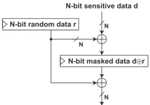
(6) T. Sugawara et al.. Microelectronics Journal 90 (2019) 63–71. Table 1 LFI profiles for 2-input NAND gate. Transistor. LFI target. PMOS NMOS NMOS. {MP3 }, {MP4 }, {MP 3 , MP 4 } ∈ ΠA =1∧ B =1 {MN3 } ∈ ΠA =0∧ B =1 {MN4 } ∈ ΠA =1∧ B =0. f(x1 , … , xi , … , xn ) = 1. Conversely, The pull-down network is conductive when f(x1 , … , xi , … , xn ) = 0. We consider an LFI on the PMOS transistor MPi controlled by xi . In the original state, MPi should be OFF, or equivalently xi = 1. A short circuit occurs when the pull-up network is originally OFF, and the LFI makes the pull-up network ON. The condition is expressed as. Fig. 7. Probabilistic network on bit flip and alarm.. f (x1 = ̂ x1 , … , xi = 1, … , xn = ̂ xn ). a bit flip. The attacker can reduce the occurrence of such a case by increasing the laser intensity. The above discussion is correct as far as the LFI position satisfies Definition 3. If there is a false positive, the laser-based probing becomes probabilistic and the efficient analysis that will be described in Sect. 4 no longer works. Such a false positive can occur when a laser covers transistors that cause opposite bit flips, e.g., {MN1 , MP1 } in Fig. 1. Besides, the laser-induced IR drop [28] can also break the assumption. It is important to note that the attacker can check such probabilistic errors at the profiling phase by extending the method described in Sect. 3.1. By repeating the same measurement for several times with a fixed LFI position and the same parameters in the second step, probabilistic false positives can be detected. By doing this, the attacker knows if the measurement is contaminated with noise, and can switch the succeeding attack strategy.. ∧ f (x1 = ̂ x1 , … , xi = 0, … , xn = ̂ xn ) = 1. If there exists unique1 ̂ x1 , … , ̂ xi−1 , ̂ xi+1 , … ̂ xn satisfying the above condition, we have. {MPi } ∈ Π(x1 =̂x1 )∧···∧(xi =1)∧···∧(xn =̂xn ) .. (4). Similarly, we can consider an LFI on the NMOS transistor MNi controlled by xi . MNi is originally OFF when xi = 0. A short circuit occurs when the pull-down network is originally OFF, and the LFI makes the pull-down network ON. The condition is expressed as f (x1 = ẋ 1 , … , xi = 0, … , xn = ẋ n ). ∧ f (x1 = ẋ 1 , … , xi = 1, … , xn = ẋ n ) = 1, If there exists unique ẋ1 , … , ẋi −1 , ẋi +1 , … ẋn satisfying the condition, we have. {MNi } ∈ Π(x1 =ẋ 1 )∧···∧(xi =0)∧···∧(xn =ẋ n ) .. 3.4. Countermeasure. (5). Countermeasures against the proposed attack are discussed. A common strategy for side-channel attack is to remove the correlation between then intermediate value and the side-channel leakage. The countermeasure shown in Fig. 8 efficiently thwarts the laserbased probing on memory. In the countermeasure, a target data d is stored as a share (r, d ⊕ r). The attacker gets no information about d by probing either r or d ⊕ r. Therefore, the countermeasure thwarts an attack with a single probe, i.e., LFI with a single laser. However, the countermeasure is no longer effective if we consider the attack on a combinatorial circuit. That is because the original value d is reconstructed at the XOR gate. To thwart the probing attack on combinatorial circuits, cryptographic computation should be conducted by using the shares without reconstructing the original value. The countermeasures based on multiparty computation (MPC) satisfy the requirement [12]. Such MPC-based countermeasures are also effective against side-channel attack [20,22].. 3.3. Errors in sensing In this section, we discuss errors in the bit flip detector. So far, we considered an ideal sensor that detects a bit flip with 100% accuracy. In reality, however, the bit flip detector is error-prone. The bit flip detector detects an anomaly by thresholding an analog physical quantity. The threshold is essential in discussing errors. In the bit flip detector, a false negative means a release of a faulty output which is unacceptable. Therefore, the threshold should be determined so that the probability of false negatives becomes negligibly small. Fig. 7 shows a probabilistic network representing the laser-based probing. The network is asymmetric because there is no false negative. Meanwhile, false positives can occur at the probability 𝜖 . An important observation is that if the attacker observes the absence of an alarm, it always means that there is no bit flip, or equivalently Predicate = false. Therefore, as far as the ineffective fault is used, the attacker can make error-free measurement. As shown in Fig. 7, the probability to observe the absence of an alarm is (1 − 𝜖)∕2. Consequently, to observe the absence of an alarm for M times, the attacker should make the laser-based probing 2 M∕(1 − 𝜖) times. It is important to note that the attacker can reduce 𝜖 by improving an instrument. A false positive occurs when the LFI-induced short-circuit current is sufficient to trigger the bit flip detector but insufficient to cause. 1 If more than two tuples satisfy the condition, we cannot decide which one is taken upon observing an alarm. In this case, the presence of an alarm does not necessarily mean that the predicate is true.. Fig. 8. Masking. 67.
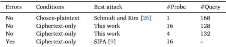
(7) T. Sugawara et al.. Microelectronics Journal 90 (2019) 63–71. Although such an MPC-based countermeasure is costly,2 it can be an efficient option because it is effective against two attacks: if we use an MPC-based countermeasure against SCA, the protection against the proposed attack comes for free.. Table 2 Attack table.. 4. Cryptanalysis using sensor-based probing. Errors. Conditions. Best attack. #Probe. #Query. No No No Yes. Chosen-plaintext Ciphertext-only Ciphertext-only Ciphertext-only. Schmidt and Kim [26] This work This work SIFA [9]. 1 16 4 16. 168 128 132 –. 4.1. Attack model We model the laser-based probing in the context of cryptanalysis. Firstly, we consider a chosen-message attack in which an attacker can choose an input message. That is modeled by the oracle in Alg. 2. The attacker firstly determines a target Predicate and the corresponding LFI position T ∈ ΠPredicate . Then, the attacker calls an encryption with a message m and makes LFI based on the profile. When the attacker observes the absence of an alarm, the attacker learns that Predicate = false and obtains a ciphertext. If there is an alarm, on the other hand, the attacker learns that Predicate = true and obtains the null symbol ⊥ meaning that a ciphertext is unavailable. Alg. 2 is different from conventional probing attacks on the point ciphertext can be unavailable. Secondly, we consider a ciphertext-only attack in which an attacker can neither choose nor know a message. The ciphertext-only attack is commonly considered in a theoretical analysis of cryptography and is also practical. For Example, in a variant of challenge and response authentication, a verifier generates a message m and encrypts it to a ciphertext c = Enck (m). Then, the verifier sends c to a prover. The prover decrypt the message with a pre-shared key K and recovers a message m′ = Deck (c). Then, the prover sends m′ back to the prover. The verifier authenticates the prover upon m = m′ . In the above setting, an attack by a malicious prover is a ciphertext-only attack. The side-channel oracle in the ciphertext-only attack is shown in Alg. 3. In this case, the attacker observes either (true, c) or (false, ⊥). It is important that (false, ⊥) is hardly exploitable because the attacker has neither a plaintext nor a ciphertext. Therefore, the attacker should rely on the ineffective case (false, ⊥) for analysis.. relies on the chosen plaintext, it cannot be used under the ciphertextonly attack. Therefore the ones described in the next sections are the best attacks. Secondly, we consider the case in which the result of probing is contaminated with noise. This is beyond the scope of the conventional probing attack. So far, the best attack to exploit the leakage is SIFA [9] described in Sect. 2.3. If we consider a SIFA on the AES S-boxes in the 10th round, 16 distinct probes are needed. The number of queries to recover the key depends on the signal-to-noise ratio and thus not shown in Table 2.. 4.2. Probing on the 10th round We discuss the attack on the 10th round of AES by exploiting the leakage in the ciphertext-only attack described in Alg. 3. The attack assume a LFI target in which Predicate is univariate, i.e., a bit-set/reset fault. This is a simple extension of the Clavier-Wurcker attack [6] considering a bit-set/reset fault (cf. byte-wise fault). We consider a bit-reset fault at the most significant bit (MSB) of an S-box input denoted by MSB[S-box−1 (z)] where z is an Sbox output. In other words, the attacker uses the LFI position T ∈ ΠMSB[S-box−1 (z)]=1 . The attacker obtain a set of correct ciphertexts {c1 , … , cN } by Alg. 3. In the correct ciphertexts, the Predicate is false and thus MSB[S-box−1 (z)] = 0. The set of ciphertexts can be analyzed using Alg. 4. The procedure has a nested loop for all the key candidates and ciphertexts. At the line #4, a target byte x is extracted from a ciphertext ci by a sub-routine namely slice. Then, MSB of an S-box input MSB[S-box−1 (x ⊕ k)] is calculated based on a hypothetical key byte k. For a correct key candidate k∗ ,. Algorithm 2 Chosen-message attack oracle CPA(m, T) Require: Message m and the position of LFI T ∈ ΠPredicate Ensure: The value of the Predicate and a ciphertext if available 1: c ← EncK (m) meanwhile laser-based probing p ← LPredicate (T) is conducted. 2: if p = true then 3: Return (true, c) 4: else 5: Return (false, ⊥) 6: end if. ∀x MSB[S-box−1 (x ⊕ k∗ )] = 0.. (6). Accordingly, a set of key candidates satisfying Eq. (6) for any ci , denoted by , is returned. The number of key candidates is roughly halved for each ciphertext. Therefore, a correct key is recovered with roughly 8 ciphertexts. By repeating the same procedure, the remaining key bytes can be recovered. For full-key recovery, 16 distinct LFI positions are needed. Accordingly, the analysis uses 8 × 16 = 128 correct ciphertexts.. Algorithm 3 Ciphertext-only attack oracle COA(T). Require: The position of LFI T ∈ ΠPredicate Ensure: The value of the Predicate and a ciphertext if available 1: m ← U{0, 1}128 2: (p, c) ←CPA(m, T) 3: Return (p, c). Algorithm 4 Attack using probing on the 10th round. Require: A set of ciphertexts {c1 , … , cN }. Ensure: A set of key candidates . 1: ← {0, … , 28 − 1} 2: for k = 0, … , 28 − 1 do 3: for i = 1, … , N do 4: x ← slice(ci ) 5: ti ←MSB[S − box−1 (x ⊕ k)] 6: end for 7: if not t1 = t2 = · · · tN = 0 then 8: ← ⧵ {k} 9: end if 10: end for 11: Return . We discuss the best attacks on AES in different conditions based on Table 2. Firstly, we consider the error-free case. The case without fault negatives as discussed in the Sect. 3.3 also falls in this category. In the chosen-plaintext attack, the conventional probing attack by Schmidt and Kim [26] is still effective to attack AES. With the Schmidt-Kim attack, a full AES key can be recovered by using only one LFI position and 168 encryption queries on average. Since the Schmidt-Kim attack. 2 Moradi et al. reported that the circuit area becomes 400% larger using an MPC-based countermeasure with 3 shares [20].. 68.
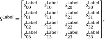
(8) T. Sugawara et al.. Microelectronics Journal 90 (2019) 63–71. 4.3. Probing on the 9th round. where. Ψ(y0 , y1 , y2 , y3 ) = 𝜓(0x70, y0 ) ⊕ 𝜓(0xd0, y1 ) ⊕ 𝜓(0xb0, y2 ). We discuss the attack on the 9th round of AES in the ciphertext-only attack. The extension to the 9th round is not straightforward. The differential analysis is a common strategy for extending a target round [26]. We cannot use the strategy because a faulty ciphertext is unavailable. Moreover, since this is the ciphertext-only attack, a difference between messages is also unavailable. To address the problem, a technique from Matsui’s linear cryptanalysis [16] is introduced. We first define some notations. The 16-byte AES state is represented by SLabel in which Label is a text representing the round and operation. Each byte in the state is represented as. SLabel. ⎡sLabel ⎢ 00 ⎢sLabel = ⎢ 01 Label ⎢s02 ⎢ Label ⎣s03. sLabel 10. sLabel 20. sLabel 11 sLabel 12 sLabel 13. sLabel 21 sLabel 22 sLabel 23. ⎤ sLabel 30 ⎥ Label s31 ⎥ ⎥, sLabel ⎥ 32 ⎥ sLabel ⎦ 33. ⊕ 𝜓(0x90, y3 ). In the bit-level representation, Eq. (10) can also be expressed as x0 (7) = y0 (6) ⊕ y0 (5) ⊕ y0 (4) ⊕ y1 (7) ⊕ y1 (6) ⊕ y1 (4). ⊕ y2 (7) ⊕ y2 (5) ⊕ y2 (4) ⊕ y3 (7) ⊕ y3 (4).. Similar linear equation can be found for any xi (j) where i ∈ [0, … , 4], j ∈ [0, … 7]. The linear equation is used in linear cryptanalysis. The right-hand side of equation (10) satisfy that. Ψ(y0 , y1 , y2 , y3 ) = Ψ(sMC9 , sMC9 , sMC9 , sMC9 ) 00 01 02 03 ⊕ k900 , sAR9 ⊕ k901 , sAR9 ⊕ k902 , sAR9 ⊕ k903 ) = Ψ(sAR9 00 01 02 03. (7). = Ψ(sAR9 , sAR9 , sAR9 , sAR9 ) ⊕ Ψ(k900 , k901 , k902 , k903 ). 00 01 02 03. is denoted by sLabel (l). In addition, we introduce the l-th bit of sLabel ij ij masking:. 00. the attacker obtain a set of correct ciphertexts {c1 , … , cN } satisfying (7) = 0. Therefore, The left-hand side of Eq. (10) satisfies sSB9 00. Definition 4. [Masking of elements over GF(28 )] Masking ψ ∶ (GF(28 ) × GF(28 ) → GF(2)) is a map defined by 7 ⨁. {a(i) ∧ b(i)}.. 𝜓(0x80, sSB9 ) = sSB9 (7) = 0. 00 00. (8). (13). By combining Eqs. (10), (12) and (13), we get. i=0. We describe the proposed attack using the diagram in Fig. 9. We consider MixColumns given by ⎡y0 ⎤ ⎡2 ⎢ ⎥ ⎢ ⎢y1 ⎥ ⎢1 ⎢ ⎥=⎢ ⎢y2 ⎥ ⎢1 ⎢ ⎥ ⎢ ⎣y3 ⎦ ⎣3. (12). Note that we used the linearity of the map Ψ to obtain Eq. (12). Since the key is fixed, Ψ(k900 , k901 , k902 , k903 ) is a 1-bit constant. In the following, we consider a bit-reset fault on sSB9 (7). In other 00 words, the attacker uses the LFI position T ∈ ΠsSB9 (7)=1 . By Alg. 3,. where sLabel ∈ GF (28 ). When a bit-level representation is needed, the ij. 𝜓(a, b) =. (11). 3. 1. 2. 3. 1. 2. 1. 1. 1⎤ ⎡x0 ⎤ ⎥ ⎢ ⎥ 1⎥ ⎢x1 ⎥ ⎥ ·⎢ ⎥, 3⎥ ⎢x2 ⎥ ⎥ ⎢ ⎥ 2⎦ ⎣x3 ⎦. Ψ(sAR9 , sAR9 , sAR9 , sAR9 ) = constant. 00 01 02 03. Eq. (14) is used as a distinguisher. Alg. 5 shows the proposed attack procedure. The input to the algorithm is a set of ciphertexts namely {c1 , … , cN } satisfying that the Predicate is false. In other words, (7) = 0 is satisfied for any ci . The purpose of the algorithm is to sSB9 00 , k10 , k10 , and k10 . The recover 4 bytes of the round key K10 namely k10 00 13 22 31 procedure has a nested loop: the outer loop is for examining all the 32-bit key space meanwhile the inner loop is for {c1 , … , cN }. At the line #5, the corresponding bytes namely c00 , c13 , c22 , and c31 are extracted from ci by the sub-procedure slice4. Then, the 4-byte , sAR9 , sAR9 , and sAR9 are calculated based on a intermediate state sAR9 00 01 02 03 hypothetical key k. Then, a 1-bit value ti is evaluated as. (9). where xi , yi ∈ GF(28 ). MSB of x0 namely x0 (7) is considered. In that case, the following linear equation is satisfied at probability 1:. 𝜓(0x80, x0 ) = 𝜓(0x70, y0 ) ⊕ 𝜓(0xd0, y1 ) ⊕ 𝜓(0xb0, y2 ) ⊕ 𝜓(0x90, y3 ) = Ψ(y0 , y1 , y2 , y3 ),. (14). (10). Fig. 9. Illustration of attack by probing on the 9th round. 69.
(9) T. Sugawara et al.. Microelectronics Journal 90 (2019) 63–71. 5. Conclusion. ti ← Ψ(sAR9 , sAR9 , sAR9 , sAR9 ) 00 01 02 03. (15) In this paper, we conducted the first security evaluation of the sensor-based countermeasures against laser fault injection. The attack transforms a sensor into a side-channel oracle that enables an attacker to probe an internal state of a target chip non-invasively. The proposed attack is applicable to any countermeasures as far as the following two conditions are satisfied: (i) the target obeys bit-set/reset fault model and (ii) an alarm is raised on a bit flip. The leakage can be used to attack cryptography. Notably, with the proposed cryptanalytic technique, AES can be attacked using 132 ciphertexts even under the ciphertext-only setting. Experimental verification of the proposed attack using a chip having a sensor-based countermeasure is an important open problem. The proposed cryptanalytic technique works with the bit-set and bit-reset faults only. An attack that efficiently exploits the LFI position corresponding to a multivariate Predicate is an open problem.. For a correct key candidate, ti should be the same for any i because of Eq. (14). Therefore, the key candidate remains if t1 = t2 = · · · = tN . Otherwise, the candidate is rejected. Finally, the algorithm output a set of remaining key candidates . Algorithm 5 Attack using probing on the 9th round. Require: A set of ciphertexts {c1 , … , cN }. Ensure: A set of key candidates . 1: ← {0, … , 232 − 1} 2: for k = 0, … , 232 − 1 do ‖k10 ‖k10 ‖k10 ← k 3: k10 00 13 22 31 4: for i = 1, … , N do 5: (c00 , c13 , c22 , c31 ) ← slice4(ci ) 6: sAR9 ← S-box−1 (c00 ⊕ k10 ) 00 00 AR9 7: s01 ← S-box−1 (c13 ⊕ k10 ) 13 8: sAR9 ← S-box−1 (c22 ⊕ k10 ) 02 22 9: sAR9 ← S-box−1 (c31 ⊕ k10 ) 03 31 AR9 AR9 AR9 10: ti ← Ψ(sAR9 , s , s , s ) 00 01 02 03 11: end for 12: if not t1 = t2 = · · · = tN then 13: ← ⧵ {k} 14: end if 15: end for 16: Return . Acknowledgement We thank the anonymous reviewers for their valuable comments. The study is supported by JSPS KAKENHI Grant Number JP18H05289 and JP18K18047. References [1] Dan Boneh, Richard A. DeMillo, Richard J. Lipton, On the importance of checking cryptographic protocols for faults (extended abstract), in: Fumy Walter (Ed.), Advances in Cryptology - EUROCRYPT 97, International Conference on the Theory and Application of Cryptographic Techniques, Konstanz, Germany, May 11-15, 1997, Proceeding, Volume 1233 of Lecture Notes in Computer Science, Springer, 1997, pp. 37–51. [2] Possamai Bastos Rodrigo, Leonel Acunha Guimaraes, Frank Sill Torres, Laurent Fesquet, Architectures of bulk built-in current sensors for detection of transient faults in integrated circuits, Microelectron. J. 71 (2018) 70–79. [3] Eli Biham, Adi Shamir, Differential fault analysis of secret key cryptosystems, in: Burton S. Kaliski Jr. (Ed.), Advances in Cryptology - CRYPTO 97, 17th Annual International Cryptology Conference, Santa Barbara, California, USA, August 17-21, 1997, Proceedings, Volume 1294 of Lecture Notes in Computer Science, Springer, 1997, pp. 513–525. [4] Champeix Clement, Nicolas Borrel, Jean-Max Dutertre, Robisson Bruno, Mathieu Lisart, Alexandre Sarafianos, Experimental validation of a bulk built-in current sensor for detecting laser-induced currents, in: 21st IEEE International On-Line Testing Symposium, IOLTS 2015, Halkidiki, Greece, July 6-8, 2015, IEEE, 2015, pp. 150–155. [5] Renesas Technology Corporation. Ic Card System Using Photo-Detectors for Protection, 2003. US Patent US7042752. [6] Christophe Clavier, Wurcker Antoine, Reverse engineering of a secret AES-like cipher by ineffective fault analysis, in: Fischer and Schmidt [10], 2013, pp. 119–128. [7] Jean-Max Dutertre, Vincent Beroulle, Philippe Candelier, Stephan De Castro, Louis-Barthelemy Faber, Marie-Lise Flottes, Philippe Gendrier, David Hely, Regis Leveugle, Paolo Maistri, Giorgio Di Natale, Athanasios Papadimitriou, and Bruno Rouzeyre. Laser fault injection at the CMOS 28 nm technology node: an analysis of the fault model. In Fischer and Schmidt [10], pages 16. [8] Jean-Max Dutertre, Possamai Bastos Rodrigo, Potin Olivier, Marie-Lise Flottes, Rouzeyre Bruno, Giorgio Di Natale, Sensitivity tuning of a bulk built-in current sensor for optimal transient-fault detection, Microelectron. Reliab. 53 (911) (2013) 1320–1324. [9] Christoph Dobraunig, Maria Eichlseder, Thomas Korak, Stefan Mangard, Florian Mendel, Robert Primas, SIFA: exploiting ineffective fault inductions on symmetric cryptography, IACR Trans. Cryptogr. Hardw. Embed. Syst. 2018 (3) (2018) 547–572. [10] Clemens Helfmeier, Dmitry Nedospasov, Christopher Tarnovsky, Jan Starbug Krissler, Christian Boit, Jean-Pierre Seifert, Breaking and entering through the silicon, in: Ahmad-Reza Sadeghi, Virgil D. Gligor, Moti Yung (Eds.), 2013 ACM SIGSAC Conference on Computer and Communications Security, CCS13, Berlin, Germany, November 4-8, 2013, ACM, 2013, pp. 733–744. [11] Helena Handschuh, Paillier Pascal, Jacques Stern, Probing attacks on tamper-resistant devices, in: etin Kaya Ko, Christof Paar (Eds.), Cryptographic Hardware and Embedded Systems, First International Workshop, CHES99, Worcester, MA, USA, August 12-13, 1999, Proceedings, Volume 1717 of Lecture Notes in Computer Science, Springer, 1999, pp. 303–315. [12] Yuval Ishai, Sahai Amit, A. Wagner David, Private circuits: securing hardware against probing attacks, in: Dan Boneh (Ed.), Advances in Cryptology - CRYPTO 2003, 23rd Annual International Cryptology Conference, Santa Barbara, California, USA, August 17-21, 2003, Proceedings, Volume 2729 of Lecture Notes in Computer Science, Springer, 2003, pp. 463–481.. Similarly to the 10th round attack, the number of key candidates is roughly halved for each ciphertext. However, one extra ciphertext is needed to fix the unknown constant in Eq. (14) determined by Ψ(k900 , k901 , k902 , k903 ). As a result, the key space is expected to be reduced to 32 − (N − 1) bits by using N ciphertexts and run Alg. 5. Therefore, the expected number of ciphertexts needed to determine the 4 key bytes uniquely is 33. The attacker repeats the same procedure for different columns to get the remaining bytes of the key. As a result, full key recovery needs laser injections to 4 different positions and 4 × 33 = 132 ciphertexts. Alg. 5 is verified through an experiment. In the experiment, a set of ciphertexts with a constraint that sSB9 (7) = 0 is generated by sim00 ulation. Then, Alg. 5 is executed, and the number of remaining key candidates are evaluated. Table 3 summarizes the number of ciphertexts N, the number of remaining key candidate ||, and the number of remaining key bits log2 ||. The result clearly shows that log2 || ≈ 32 − (N − 1) as expected.. Table 3 Experimental result. # ciphertexts N. # remaining key candidates ||. log2 ||. 1 2 3 ⋮ 20 21 22 23 24 25 26 27 28 29 30 31 32 33 34. 4294967296 2147495936 1073678336 ⋮ 8166 4092 2041 1009 499 262 130 77 40 19 9 5 3 2 1. 32.00 31.00 30.00 ⋮ 13.00 12.00 11.00 9.98 8.96 8.03 7.02 6.27 5.32 4.25 3.17 2.32 1.58 1.00 0.00. 70.
(10) T. Sugawara et al.. Microelectronics Journal 90 (2019) 63–71 [22] Svetla Nikova, Christian Rechberger, Rijmen Vincent, Threshold implementations against side-channel attacks and glitches, in: Peng Ning, Sihan Qing, Ninghui Li (Eds.), Information and Communications Security, 8th International Conference, ICICS 2006, Raleigh, NC, USA, December 4-7, 2006, Proceedings, Volume 4307 of Lecture Notes in Computer Science, Springer, 2006, pp. 529–545. [23] Egas Henes Neto, Ivandro Ribeiro, Michele G. Vieira, Gilson I. Wirth, Fernanda Lima Kastensmidt, Using bulk built-in current sensors to detect soft errors, IEEE Micro 26 (5) (2006) 10–18. [24] Riscure. Laser station 2. https://www.riscure.com/product/laser-station-2/. [25] Bodo Selmke, Johann Heyszl, Sigl Georg, Attack on a DFA protected AES by simultaneous laser fault injections, in: 2016 Workshop on Fault Diagnosis and Tolerance in Cryptography, FDTC 2016, Santa Barbara, CA, USA, August 16, 2016, IEEE Computer Society, 2016, pp. 36–46. [26] Jrn-Marc Schmidt, Chong Hee Kim, A probing attack on AES, in: Kiwook Sohn, Moti Yung (Eds.), Kyo-Il Chung, Information Security Applications, 9th International Workshop, WISA 2008, Jeju Island, Korea, September 23-25, 2008, Revised Selected Papers, Volume 5379 of Lecture Notes in Computer Science, Springer, 2008, pp. 256–265. [27] Takeshi Sugawara, Natsu Shoji, Kazuo Sakiyama, Kohei Matsuda, Noriyuki Miura, Makoto Nagata, Exploiting bitflip detector for non-invasive probing and its application to ineffective fault analysis, in: 2017 Workshop on Fault Diagnosis and Tolerance in Cryptography, FDTC 2017, Taipei, Taiwan, September 25, 2017, IEEE Computer Society, 2017, pp. 49–56. [28] Raphael Andreoni Camponogara Viera, Jean-Max Dutertre, Possamai Bastos Rodrigo, Philippe Maurine, Role of laser-induced IR drops in the occurrence of faults: assessment and simulation, in: DSD, IEEE Computer Society, 2017, pp. 252–259. [29] Haibin Wang, Rui Liu, Li Chen, J.-S. Bi, M.-L. Li, Yuanqing Li, A novel built-in current sensor for N-WELL SET detection, J. Electron. Test. 31 (4) (2015) 395–401. [30] Zhichao Zhang, Yi Ren, Li Chen, Nelson J. Gaspard, Arthur F. Witulski, W. Timothy Holman, Bharat L. Bhuva, Shi-Jie Wen, Ramaswami Sammynaiken, A bulk built-in voltage sensor to detect physical location of single-event transients, J. Electron. Test. 29 (2) (2013) 249–253.. [13] Marc Joye, Michael Tunstall, Fault Analysis in Cryptography, Springer Publishing Company, 2012. Incorporated. [14] Joint Interpretation Library, Application of Attack Potential to Smartcards Version 2.9, 2013, https://www.sogis.org/. [15] Li Yang, Kazuo Sakiyama, Shigeto Gomisawa, Toshinori Fukunaga, Junko Takahashi, Kazuo Ohta, Fault sensitivity analysis, in: Stefan Mangard and Franois-Xavier Standaert, Editors, Cryptographic Hardware and Embedded Systems, CHES 2010, 12th International Workshop, Santa Barbara, CA, USA, August 17-20, 2010. Proceedings, Volume 6225 of Lecture Notes in Computer Science, Springer, 2010, pp. 320–334. [16] Mitsuru Matsui, Linear cryptanalysis method for DES cipher, in: Tor Helleseth (Ed.), Advances in Cryptology - EUROCRYPT 93, Workshop on the Theory and Application of of Cryptographic Techniques, Lofthus, Norway, May 23-27, 1993, Proceedings, Volume 765 of Lecture Notes in Computer Science, Springer, 1993, pp. 386–397. [17] K. Matsuda, T. Fujii, N. Shoji, T. Sugawara, K. Sakiyama, Y. Hayashi, M. Nagata, N. Miura, A 286 f2/cell distributed bulk-current sensor and secure flush code eraser against laser fault injection attack on cryptographic processor, IEEE J. Solid State Circuits 53 (11) (Nov 2018) 3174–3182. [18] Kohei Matsuda, Noriyuki Miura, Makoto Nagata, Yu-ichi Hayashi, Tatsuya Fujii, Kazuo Sakiyama, On-chip substrate-bounce monitoring for laser-fault countermeasure, in: 2016 IEEE Asian Hardware-Oriented Security and Trust, AsianHOST 2016, Yilan, Taiwan, December 19-20, 2016, IEEE Computer Society, 2016, pp. 1–6. [19] Stefan Mangard, Elisabeth Oswald, Thomas Popp, Power Analysis Attacks Revealing the Secrets of Smart Cards, Springer, 2007. [20] Amir Moradi, Axel Poschmann, San Ling, Christof Paar, Huaxiong Wang, Pushing the limits: a very compact and a threshold implementation of AES, in: Kenneth G. Paterson (Ed.), Advances in Cryptology - EUROCRYPT 2011 - 30th Annual International Conference on the Theory and Applications of Cryptographic Techniques, Tallinn, Estonia, May 15-19, 2011. Proceedings, Volume 6632 of Lecture Notes in Computer Science, Springer, 2011, pp. 69–88. [21] Ashay Narsale, Michael C. Huang, Variation-tolerant hierarchical voltage monitoring circuit for soft error detection, in: 10th International Symposium on Quality of Electronic Design (ISQED 2009), 16-18 March 2009, San Jose, CA, USA, IEEE Computer Society, 2009, pp. 799–805.. 71.
(11)
Figure
![Fig. 1. Mechanism behind laser fault injection [18].](https://thumb-us.123doks.com/thumbv2/123dok_us/1359386.2681895/3.892.191.709.882.1090/fig-mechanism-behind-laser-fault-injection.webp)


+3
Related documents