MEDICAL IMAGING IN A CLOUD COMPUTING ENVIRONMENT
Louis Parsonson, Li Bai
School of Computer Science, University of Nottingham, Jubilee Campus, Wollaton Road, Nottingham, NG8 1BB [email protected], [email protected]
Laurence Bourn, Atif Bajwa, Soeren Grimm
Biotronics3D, 16 Heron Quays, Canary Wharf, London, E14 4JB, UK [email protected], [email protected], [email protected]
Keywords: Medical imaging, volume rendering, cloud computing
Abstract: In this paper we present a cloud computing environment for medical imaging which deals with the issues of scaling a traditionally single-user solution to a software-as-a-service solution. We will first introduce volume rendering for medical imaging, and the issues with volume rendering of medical images on the cloud. We will then describe our method for accelerating CPU based volume rendering on the cloud and for scaling the system to a software-as-a-service solution.
1 INTRODUCTION
Over the past few years, there has been a change in the way software solutions are delivered. Provision of software has moved from locally installed systems to remotely invoked virtual instances, accessed through a web browser or alike. The motivation is a paradigm shift due to increased prevalence of the Internet, an increase in the commoditization of IT hardware, and pressure to cut IT budgets. Consequently, software is no longer delivered as a product, but offered as a service, i.e. Software as a Service (SaaS) (Jaekel et al, 2010).
The removal of specialised hardware requirements and its associated capital expenditure are both instrumental to the success of this strategy. SaaS requires service providers to assume risks associated with start-up costs, while facilitating consumers with immediate access to purchased software solutions: first contact with the product involves gaining access to the services as opposed to cumbersome, failure prone, invasive installation procedures. Successful examples of the SaaS paradigm include Google Docs, a web-based text editing solution freely available over the internet, VPS NET, a virtual private server hosting company, and Facebook, a social networking website. For many of these services, access only requires account creation and access to an internet-enabled computer Centralized information can be manipulated and shared in a flexible and transparent manner. Additionally, the service provider can update and
modify the service without requiring interruption or active participation of the user. SaaS solutions are also suitable for the ‘pay-as-you-go’ charging scheme, which allows users to create a subscription which can be cancelled and/or upgraded at any time, without incurring administrative costs to the solution provider.
SaaS has interesting implications for medical imaging applications. State-of-the-art systems are currently installed on high-end, standalone workstations, often requiring bespoke hardware. This entails an overburden in administration of load balancing and redundancy control. These standalone workstations are often idle for large periods of time, rendering them costly, inefficient and promptly outdated. Additionally, due to their cost, they are often shared, causing scheduling conflicts, and reducing overall efficiency.
A medical imaging cloud offers an alternative solution. It removes the need for expensive workstations, although presents difficulties of its own. The processing power required for a medical imaging application is more than a cloud solutions have typically provided. In this paper we show how to effectively apply the cloud computing model to a medical imaging platform.
2 MEDICAL IMAGING
Medical imaging deals with the capture and analysis of images of the body, taken using equipment
utilising electromagnetic radiation. This covers many techniques including x-ray based methods such as radiography and Computed Tomography (CT), ultrasound, Magnetic Resonance Imaging (MRI), and more. Images in this context are often referred to as slices since they describe a cross-section slice of a particular part of the body. While some imaging techniques result in a single image, for instance an x-ray of a broken bone, others can produce multiple images, such as an MRI scan. If a scan acquires multiple images, the resulting collection is referred to as a series. In some cases, multiple series of images are taken over a period of time. In all of these cases, the collected scan data of a single patient is called a study.
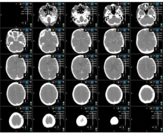
These studies are then sent for analysis by a specialist. This specialist will have a set of such studies to analyse, and after completing analysis will send the results to the patients physician for further treatment. Traditionally, studies are viewed as single images or as a set of consecutive slices (Figure 1.). However, a single study can comprise of as many as a thousand images, resulting in more than 1.5 gigabytes of data. Because of this, difficulties can arise when processing scans on a slice by slice basis. The use of volumes is therefore desirable. By assigning a thickness to each slice in a scan (which can be determined by the interval at which the patient was scanned) these slices can be composited to a volume representation of the patient’s body. This volume can then be used to produce a three-dimensional visualisation of the patient through volume rendering.
Figure 1: Display showing multiple images in a series.
3 VOLUME RENDERING
Volume rendering is the method by which projections of 3D volumes are displayed as 2D images. Early implementations of volume rendering techniques focused on rendering of texture data, initially as a set of blended 2D textures and later, as the hardware permitted, utilising 3D textures (Dachille et al, 1998), before ray casting was implemented (Kruger et al, 2003).
3.1 Direct Volume Rendering
Direct Volume Rendering (DVR) generates images without the need to create an intermediate polygonal representation of a volume. Instead, the volume data set is projected onto an image plane. In image-space oriented ray casting approaches, rays are cast from the view-point through the view-plane into the volume, see Figure 2. The volume is equidistantly sampled along the ray and the volume integral is computed by repeated accumulation of colours and opacities.
Figure 2: Ray casting
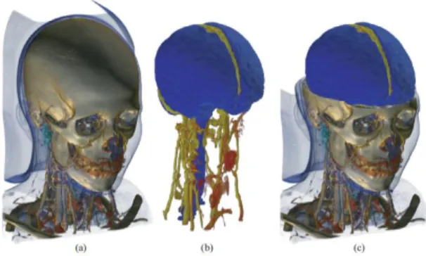
At every sampling position a scalar value is interpolated between the corresponding surrounding eight voxels, that is, in the logical three dimensional extension of a pixel. This value is then classified according to a transfer function. If the sample is non-transparent, a gradient is computed from the surrounding voxels, in order to apply shading. Finally, the sample is composited with the previous samples of the ray. Figure 3 shows a typical example of a volume render: (a) shows a render of the full volume; (b) and (c) show renders containing segmentation information where a second transfer function has been applied.
Figure 3: Volume render
Three main volume rendering approaches can be distinguished. Two of them are hardware based; the first one utilizes high-end Graphics Processing Units (GPUs) (Heng et al, 2005); the second requires special purpose hardware (Shen et al, 2007); the third is CPU based volume rendering.
3.2 Volume Rendering on the GPU
GPUs are highly parallel optimisations of processor architecture, and ray casting has been shown to work well on GPUs thanks to this parallelism. In hand with this are recent advances in hardware which have made modification of the graphics pipeline commonplace.
In a GPU based implementation of a volume renderer, entry points of rays intersecting a volume are computed by rendering the front faces of the bounding cube of the volume as a colour map. The back faces are then rendered in a similar manner to calculate the direction of each ray through the volume. Using this information the process then steps through the volume along the direction of the ray, interpolating tri-linearly to calculate colour values (Kruger et al, 2003).
Thanks to GPU architecture being aimed at floating point mathematics, these operations can be somewhat faster than they would be on the CPU. It does, however, involve transfer of large amounts of data from main memory into video memory, which can cause significant slow-down. In general, graphics hardware often has access to less memory than the CPU. Today’s best cards have a maximum of 6GB (for example: Nvidia Tesla M2070) in comparison with multi-core CPU servers where 256GB is not uncommon. Rendering of many data sets would therefore require frequent swapping of data between main and video memory. In addition, most GPU APIs are focused on computer game technologies, where precision and concurrency are rarely an issue.
3.3 Volume Rendering in Hardware
Operations which would take time to emulate in software or on a GPU can be specifically mapped onto the hardware to increase performance (Meissner et al, 2001). Volume rendering hardware is specifically optimised for the task at hand.
Pure hardware based volume rendering solutions provide real-time performance and high quality rendering. Consequently they are the most applied approach in practice. Current high-end solutions offer high performance on volumes of 5123 voxels, with as much as four gigabytes of dedicated memory and options for clustering machines together. These can, however, involve using imaging applications specific to the hardware manufacturer, tying users to a single vendor.
3.4 Volume Rendering on the CPU
Rendering on the CPU is the obvious choice in some applications, and in fact was the only choice for some time, originating before rendering on the GPU was even possible (Roth, 1982). Since this first implementation many algorithmic advances have been made.
One such advance is the shear warp algorithm (Lacroute et al, 1994), which accelerates rendering by modifying the shape of the volume in such a way that voxels are aligned in parallel to the image plane. Rays cast no longer need to worry about interpolation since each one passes perfectly though the centre of a line of voxels, with each voxel being a single step along the ray. This leads to very good cache coherency during volume traversal greatly improving the speed. However, because only one sample is made for each voxel the resulting image quality is low and insufficient for medical analysis.
There are many advantages to rendering on the CPU. Advanced visualization systems provide pre-processing features such as filtering, segmentation, and morphological operations, among others. If such operations are not supported by the hardware, they have to be performed on the CPU and data must then be transferred back to the hardware. This transfer is very time consuming, thus interactive feedback becomes problematic. In contrast, within a pure CPU based solution this transfer is unnecessary allowing more efficient processing of data (Grimm et al, 2004).
4 EFFICIENT RENDERING ON
THE CLOUD
Volume rendering offers a number of challenges, and this is reflected when scaling to a large multi-user solution such as a cloud. Memory is an important consideration. In a cloud environment each user needs access to enough memory to ensure that the system continues to run smoothly. A typical study can contain multiple series, of which an average of three hundred images per series is common. This results in each user requiring, on average, four gigabytes of memory in order to work. Loading of large data sets takes time, an issue which needs to be addressed in a cloud system. In addition, rendering of large data sets can take time without an appropriate acceleration structure. Furthermore, in a cloud environment dedicated hardware-based solutions become prohibitively expensive: setup cost, maintenance, and even scalability become limited due to hardware constraints. Finally, it is important to remember that while GPU architecture is highly parallelised, it still does not support multiple concurrent user access, so image requests would have to be served sequentially. Thus, a pure CPU based solution is by far the most suitable, and probably the only truly viable solution, for cloud based rendering.
4.2 Accelerating CPU Rendering
To accelerate CPU based rendering and image processing, the underlying memory management has to be modified. In this case we utilise a bricked memory layout. Cross-sectional data, e.g. CT and MRI, are large sets of individual images which combined form a volume in space. Physical memory is typically constructed in a sequential way, therefore the straightforward approach to loading these images into memory is to put them one after the other using a linear layout (Figure 4a):
(a) Linear layout (b) Block volume layout Figure 4: Memory layout.
This layout has several disadvantages. In a typical set of cross-sectional images, an average 30 percent of the data actually does not contain any useful information. This comes from the fact that the human body consists of a set of tubular structures
(e.g. arms, legs, and torso). A cross-sectional cut through a tubular structure using rectangular images does not contain the data well, leaving vast amounts of data to represent empty space around the body. Furthermore, in the case of an advanced medical imaging application data often needs to be processed in a non-sequential way. Volume ray casting has a strong view-dependent data access pattern, and consequently, taking a look at the typical cache hierarchy of today’s CPU (L1, L2, L3) it becomes clear that storing images linearly in memory would cause complete cache thrashing.
In order to address the aforementioned issues a significant improvement is gained if the cross-sectional data is arranged in a blocked manner. In this case we subdivide and reorganize the entire volume (one 3D-image) into smaller contiguous lightweight bricks, obtaining a structure analogous to a Rubik’s cube (Figure 4b). A blocked memory layout exhibits a variety of advantages, the first of which is saving memory. Data which contains no information can be merged into a single block - blocks are implemented in a reference counted manner. Furthermore, data can be processed in a brick-wise manner.
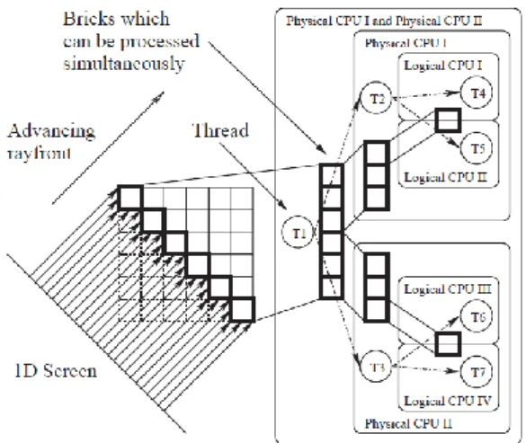
Figure 5: Volume ray casting system exploiting thread-level parallelism speedup: two physical CPUs, each with two cores.
Figure 5 shows how volume ray casting can be significantly accelerated by employing a brick-wise processing scheme. Not only is this scheme and memory layout considerably more cache friendly, it also has an inherent multi-threadability, all of which are essential to a successful cloud implementation of the rendering strategy. Additionally, considering modern hyper-threading technology in which there is a duplicated ALU but a shared cache, it becomes evident that in order to benefit from multiple cores
constant re-fetching of data from physical memory has to be avoided.
5
SCALING
TO
A
CLOUD
BASED SAAS SOLUTION
One of the main problems faced when sharing hardware and software resources between multiple users in an arbitrary manner is the robust and efficient administration of the hardware available. Not only must each user have secured data storage and privacy protection, but it must also be able to exploit its resources without having to directly control how the underlying hardware and software resources are being utilized. Cloud systems are an example of a technology that requires a managing entity that ‘virtualizes’ the usage of hardware and software in a way that each user has a direct and transparent interaction with the system. The challenge is to build a lightweight instrument that allows for seamless interaction efficiently. A dual strategy that not only permits automatic virtualization of the resources but also specializes in distributing them in a coherent manner by performing a ‘load balancing’ of the tasks on the available resources is required.
Virtualization, as described here, is instrumental to managing secure user sessions and is fundamental to the efficient distributed rendering required to perform advanced imaging applications. In particular, virtualization is achieved by creating ‘sand-boxes’, a concept that provides restricted resource sets to individual users including controlled access to data storage, hardware resources and networking privileges. This creates a local, virtual machine for each user and removes the burden of requiring them to manage how their tasks are processed by the system.
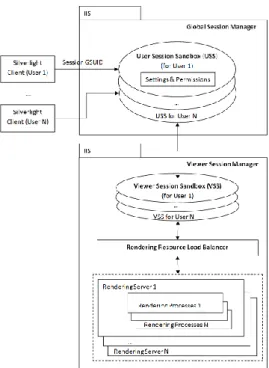
In order to achieve this securely and efficiently, the cloud system is split into the following sections: a Global Session Manager (GSM) responsible for managing user specific session sandboxes and a View Session Manager (VSM) responsible for managing viewing session sandboxes and load-balancing. The load-balancing itself is done by the Rendering Resource Load Balancer (RRLB), which is part of the VSM. Both the GSM and VSM are deployed as web services and can be mirrored for redundancy.
Figure 6: Virtualisation in the cloud.
A typical user interaction with the system is as follows: as a user successfully logs in at which point they are assigned a global session unique identifier (GSUID). This GSUID allows the user to request within the GSM a user specific session sandbox (see Figure 6). The session sandbox holds all permissions and settings for that user within the entire system (data- and hardware-wise). It can only be accessed by that user. Furthermore, this session sandbox is controlled by a configurable sliding expiration. By default, user inactivity for more than 30 minutes will immediately remove the session sandbox, effectively logging the user out. When the user wishes to view a study, assuming they have the correct permission level, the VSM requests that the RRLB return a suitable rendering node resource. A new rendering session is created and added to the user session sandbox. The rendering resource starts one or more rendering processes based on the study data. The RRLB decides on which rendering node the image generator is created based on permissions of which node can be used by the user and the current load on nodes (number of users, available memory, CPU utilization, etc.). The viewing session sandbox is also controlled by the configurable sliding expiration.
It is important, also, to consider the bandwidth needs of a cloud system dealing with large amounts of data. Such a system needs to be able to serve multiple users concurrently, as well as transfer data between internal components quickly. Due to the nature of the application, much of the traffic is in the
format of images, whether this is renders being sent from the server to the client, or scan data being uploaded from the client to the server. Even in compressed formats, image data takes a large amount of bandwidth to transmit quickly, which can have a significant impact on performance.
6 RESULTS AND CONCLUSIONS
This solution was implemented in the Biotronics3D cloud, and is currently running as 3dnetmedical. A single high-end server in the cloud can serve as many as 64 users concurrently, showing just how successful this solution is. Being a cloud, this solution is scalable, so any combination of servers can be combined for greater effect. The scalability of the cloud is an important feature, since it inherently implies a cost effective solution. At any time additional nodes can be added to the cloud to make it more powerful and the cost per user is much reduced compared to that of buying individual workstations.
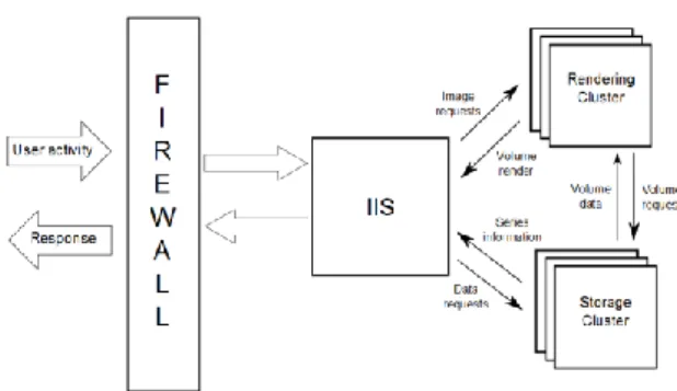
Figure 7: Overview of cloud infrastructure.
The infrastructure on which the system was implemented was comprised primarily of a firewall, for security purposes, an IIS server, a rendering cluster and a storage cluster. Both the rendering cluster and the storage cluster can be expanded at any time to cope with an increased load of users or data. Both the rendering and storage clusters accept service requests from the IIS server, since each cluster is specifically optimised for the task it performs (for instance series uploads go straight to the storage cluster, and not through the rendering cluster) (Figure 7).
Users can be classified as one of three types: casual users, active users, and power users. Whilst a power user may be using computationally expensive features of the system, e.g., choosing transformations and transfer functions, invoking the rendering cluster, casual users could be simply
viewing an image already rendered to the screen. Thus, while a 32-core machine with 64 users would imply less than a single core per user, in reality this is not the case. Memory is in fact the limiting factor.
7 REFERENCES
Jaekel M., Pott H., 2010, Cloud Computing – Software as a Service in Practice, Siemens
Jaekel M., Luhn A., 2009, Cloud Computing – Business Models, Value Creation Dynamics and Advantages for Customers, Siemens.
Shen, R., Boulanger, P., 2007, Hardware-accelerated volume rendering for real-time medical data visualization, Lecture Notes in Computer Science, Volume 4842/2007, 801-810.
Heng, Y., Gu, L., 2005, GPU-based Volume Rendering for Medical Image Visualization, Engineering in Medicine and Biology Society, IEEE-EMBS 2005. pp. 5145-5148.
Grimm S., Bruckner S., Kanitsar A., Gröller E., 2004, A refined data addressing and processing scheme to accelerate volume raycasting, Institute of Computer Graphics and Algorithms, Vienna University of Technology, Computers & Graphics 28, 2004, pp 719-729
Kruger, J., Westermann, R., 2003, Acceleration Techniques for GPU-based Volume Rendering, Computer Graphics and Visualisation Group, Technical University Munich.
Meissner M., Grimm S., Strasser W., Packer J., Latimer D., Parallel volume rendering on a single-chip SIMD architecture, IEEE 2001 symposium on parallel and large-data visualization and graphics, San Diego, California, USA.
Dachille F., Kreeger K., Baoquan C., Bitter I., Kaufman A., 1998, High-Quality Volume Rendering Using Texture Mapping Hardware, ACM SIGGRAPH/EUROGRAPHICS workshop on Graphics hardware, Lisbon, Portugal, 1998.
Drebin, R., Carpenter, L., Hanrahan, P., 1988, Volume rendering, SIGGRAPH '88 Proceedings of the 15th annual conference on Computer graphics and interactive techniques, Atlanta, Georgia, 1988. Roth S., 1982, Ray Casting for Modelling Solids,
Computer Graphics and Image Processing, Volume 18, pp. 109-144.