FACTORY AUTOMATION
POSITION ENCODING SYSTEM
POSITION ENCODING SYSTEM
WCS
THE SUCESS STORY OF
PEPPERL+FUCHS
1945
Walter Pepperl and Ludwig Fuchs lay the foundation of Pepperl+Fuchs:
The opening of a radio repair shop
1948
Manufacture of transformers
1958
Development and production of the first inductive proximity switch
1973
The first foreign subsidiary is formed in England
1979
Pepperl+Fuchs commences production in Singapore
1988
Michael Fuchs and Claus Michael take over the management of the
company and Pepperl+Fuchs becomes a limited liability company
1991
Split into Factory Automation and Process Automation divisions, new product
group level control through a company acquisition
1996
The purchase of another company establishes the encoder business
1997
New production facilities open at Veszprem/Hungary
2000
Expansion of the Factory Automation activities with the purchase of Visolux
GmbH and the Microswitch and Photoswitch interests from Honeywell;
at the same time the Process Automation sector is expanded by the takeover
of ELCON
2000
Start of manufacture at Bintan/Indonesia
2003
Takeover of the purge and pressurization systems from Bebco Industries EPS
in the USA
2004
New Data Matrix Code product range obtained through the acquisition
of Omnitron AG and the Position Encoding System, also due to an
acquisition
2005
Expansion of the Systems & Solutions business area within the Process
Automation division aided by the acquisition of EXTEC
2006
“Acquisition of the Intrinsic Safety Instrumentation (ISB) business from
Cooper Crouse-Hinds and the Separator Alarm System (SAS) business
from OJ Electronics in order to extend its Process Automation product
range; takeover of VMT Bildverarbeitungssysteme and integration into
the Factory Automation business unit.”
FACTORY AUTOMATION DIVISION
One company, two divisions
Q
Machine & Plant Engineering
Q
Print, Paper and Finishing
Q
Material Handling
Q
Packaging Industry
Q
Automotive Industry
Q
Doors, Gates and Elevators
Q
Chemical Apparatus
Q
Commercial vehicles
Q
Textile Machines
Q
Binary and analog sensors
in various technologies
Q
Inductive and
capacitive sensors
Q
Magnetic sensors
Q
Ultrasonic sensors
Q
Photoelectric sensors
Q
Vision sensors
Q
Incremental and absolute
value rotary encoders
Q
Counters and secondary
switching devices
Q
RFID Identification systems
Q
Data Matrix Identification systems
Q
AS-Interface
Q
WCS
PRODUCT AREAS FACTORY AUTOMATION
PROCESS AUTOMATION DIVISION
Q
Signal conditioners
Q
Intrinsically safe
interface
components
Q
Remote process interface
Q
Intrinsically safe fieldbus
solutions
Q
Level control sensors
Q
Operating systems for
hazardous
areas
Q
Purge/Pressurization
enclosure
systems
Q
Process measuring and control
systems engineering at the
interface
level
Q
Ex-protection training
Q
Chemical Industry,
Pharmaceutics
Q
Oil, Gas and Petrochemical
Industry
Q
Industrial and communal
waste water technology
Q
Energy Production
Q
Engineering consultant
for Process Automation
PRODUCT AREAS PROCESS AUTOMATION
Mannheim
Twinsburg
Singapore
WE ARE RIGHT THERE – WHERE OUR
CUSTOMERS ARE …
Mannheim
Mannheim is the traditional headquarters of Pepperl+Fuchs
and the center of excellence focusing on engineering. More
than 800 specialists support the activities of this principal
Pepperl+Fuchs location.
Singapore
More than 700 employees are engaged in the Singapore center
of excellence of Pepperl+Fuchs. Since 1979, all activities
associ-ated with the Asiatic economic area have been controlled from
Singapore. This region is becoming of increasing importance due
to the growth market in China.
Twinsburg
Since 1983, Twinsburg/Ohio has been the headquarters
for the American market. 250 employees on site
deve-lop specific solutions for the American customers of
Pepperl+Fuchs.
We create markets
The global presence of Pepperl+Fuchs:
• Technology centers with their own development groups in Berlin, Tuttlingen and
Sulbiate/Italy offer customers specific solutions. Furthermore the locations operate
highly flexible production in small batch sizes.
• The production facilities in Hungary and Indonesia are equipped for series
production in large quantities.
• The worldwide sales network guarantees that we are close to our customers and
enforces Pepperl+Fuchs to react swiftly and competently to customer
require-ments. You are in need of contact addresses of our sales partners?
Please try the internet at www.pepperl-fuchs.com/company/presence.
The three centers of excellence are the focal points of the global
presence of Pepperl+Fuchs
Fields and examples of application
Da te o f issu e: 1 6 . Ma y 20 076
Subject to reasonable modifications due to technical advances.Pepperl+Fuchs Group • Tel.: Germany +49 621 776-0 • USA +1 330 4253555 • Singapore +65 67799091 • Internet http://www.pepperl-fuchs.comCopyright Pepperl+Fuchs, Printed in Germany Fields and examples of applicationFields of application of the WCS
The WCS can be used wherever material handling equipment has to be controlled highly precisely down to the very millimeter. The functional principle of the WCS per-mits use in various applications, such as
• Interruption of the code rail (aisle change, points) • Applications in curves and circuits
• Use of several vehicles behind each other.
Due to the larger tolerances of the reading head relative to the code rail, the WCS3 system can be used in most applications. In some cases, however, it is of advantage to use the WCS2 in combination with the aluminium profile system (page 18 et seqq.). Below please find some examples from the vast range of applications possible:
Shelf handling units (high-bay warehouses)
Bogies, lifting gear and transversing carriages are positioned with one reading head each. Independent of the length of the code rail, the positioning is always absolutely reproducible. In case of new high-bay warehouses we recommend the use of the WCS3 system.
For retrofitting elder warehouses, it may be advantages to use WCS2 in combination with the aluminium profile system:
• Easy subsequent installation.
• High mechanical tolerances between measuring system and vehicle is possible. • Decoupling of travel vibrations.
Automatic cranes
Automatically operated cranes are a typical application for the WCS2 in combination with the aluminium profile system. A reading head is used to position the crane for the crane and trolley travel. The guide trolley guarantees the ideal position of the reading head relative to the code rail in every position, and decouples potential vibra-tions of the craneway.
Cleaning brushes for the code rails can be attached to the guide trolley as an optional feature. Thus, the WCS2 can also be used in very dusty environments, such as ce-ment works or casting workshops.
Galvanising plants
One or several vehicles behind each other on a straight travel. The vehicles transport the goods to be electroplated to the corresponding bath automatically. On account of the high and adaptable luminous power of the reading heads, the travel code system WCS has proved excellent performance also under difficult conditions.
Apart from the WCS3 system, the WCS2 with an aluminium profile system, which can be supplied with a powder coating as well, can be used as well.
Overhead conveyors
Many vehicles have to be positioned on a belt line - the WCS system offers itself as a solution. Branch lines (points) and bends can be set up. The WCS3 is especially suited for this task.
After a power failure, the current position of the vehicle is transferred to the control without delay without the vehicle having to be moved for the purpose.
The WCS can also be employed for longer travels than 314 meters. We will be pleased to help you find a solution for your special application. Please get in touch with us.
Da te o f issu e: 1 6 . Ma y 20 07
Table of contents
Table of contents Characteristics of the WCS ... 8 Description of function ... 9 WCS reading head... 10 WCS2B/WCS3B... 10Replacement of previous reading head types by WCS2B/WCS3B reading heads... 10
Installation of reading head ... 12
Mounting plate... 13
Replacement of plastic liners ... 13
Code rail ... 14
Laminate code rail ... 14
Stainless steel code rail... 14
Tensioning device for the stainless steel code rail ... 15
ID-Pads WCS3-ID70-M1 ... 15
Mounting the code rail ... 15
Mounting the code rail with the mounting bracket system... 16
Mounting WCS2 code rails with aluminium profile system... 18
Installation of WCS3 code rail with aluminium profile system ... 22
Integrating WCS code rail into conductor lines ... 25
Connection of WCS reading head to control ... 26
Reading head with RS485 interface... 26
Reading head with CANopen interface ... 28
Reading head with SSI interface ... 29
Features and options ... 30
Detection of dirt accumulation ... 30
Option H - space heating in reading head, type LS...H ... 30
Option S - velocity output, type LS...S... 30
Option D - integrated display in reading head, type LS...D ... 31
LED display on WCS3B reading head ... 31
WCS interface modules ... 32
Interface module with parallel interface... 33
Interface module with SSI interface... 34
Interface module with Profibus DP interface ... 35
Interface module with DeviceNet interface... 36
Interface module with CANopen interface... 37
Interface module with Ethernet interface... 38
Interface module with InterBus-S interface ... 39
Interface module with Profinet interface ... 40
Interface module with Modbus-RTU interface ... 41
Display and diagnosis module... 42
Connection of RS485 reading heads to interface module/control... 44
Cable routing in RS485 bus ... 44
BT111 bus terminal ... 47
Data cables and accessories ... 48
RS485 data cable... 48
SSI data cable ... 48
Data cables WCS-DCS / WCS-DCF ... 48
Overview of cable sockets and adapter cables ... 48
Notes for use ... 50
Type summary ... 51
Technical data ... 52
Order information ... 54
Characteristics of the WCS
Subject to reasonable modifications due to technical advances. Copyright Pepperl+Fuchs, Printed in Germany Pepperl+Fuchs Group • Tel.: Germany +49 621 776-0 • USA +1 330 4253555 • Singapore +65 67799091 • Internet http://www.pepperl-fuchs.com
Da te o f issu e: 1 6 . Ma y 20 07
8
Characteristics of the WCS Characteristics of the WCS• Absolute Position Encoding System • Optoelectronic principle (infrared range) • Tried-and-tested and tough
• Maintenance-friendly
• No reference points necessary • No calibration or adjustment necessary • Not sensitive to power cuts
• Positioning with millimetre accuracy and absolute reproducibility
• Determination of position values in real time and independent of temperature fluc-tuations
• Reliable reading up to a velocity of 12.5 m/sec • High resolution = ±0.4 mm
• Variable reading distance: 0.1 m ... 327 m
• Encoding system also suitable for use in bends down to 0.5 m radius
• Varied areas of application, e. g. storage and retrieval machines, traversing car-riages, electric overhead conveyors, galvanising plants, automatic and rotary cranes and lifts
• Various systems available for installing the code rail
• Connection to any control equipment possible, directly or via interface module • Facilities available for connection to many field bus systems
• Support during commissioning and maintenance from extensive system diagnosis facilities
• Extreme reliability in operation thanks to continuous self-diagnosis • Prewarning of dirt accumulation
• Optional space heating for ambient temperatures down to -40 °C • Optional digital output of variable limit overspeed
1 = Interface module 2 = Code rail 3 = Reading head
Da te o f issu e: 1 6 . Ma y 20 07
Description of Function
Description of Function Description of functionThe WCS position encoding system comprises in the main two components:the code rail. which is the information carrier for the absolute code, and the reading head which scans the code rail optoelectronically.
The code rail is installed parallel to the runway of the vehicle and thus assigns a clearl position to each point on the runway. It is possible to install the code rail only where positioning is required. The system permits the to be installed in bends and branches to be constructed. The code rails are manufactured individually for each or-der and is supplied in a bundle. Unless oror-dered otherwise, the code rail always be-gins with a position value of 0. The maximum length of the code rail is 327 m (WCS2) or 314.5 m (WCS3). Numerous fitting aids are available for speedy installation of the code rail.
The code rail is scanned with a U-shaped reading head. The reading head detects a new position value every 0.833 mm (WCS2) or 0.8 mm (WCS3). After beeing placed onto the code rail, the reading head calculates the position value without ref-erence ponits and value delay. Scanning the code rail is reproducible, reliable and independent of temperature fluctuations even at very high velocities. The positional value can be transmitted directly from the reading head to the control via a serial RS 485 interface or an SSI interface.
Various interface modules are available for connection to standard interfaces, such as: • Parallel • SSI • Profibus DP • DeviceNet • CANopen • Ethernet • Interbus-S • ProfiNet • Modbus-RTU
Up to four reading heads can be connected simultaneously to all the interface mod-ules apart from the SSI interface.
WCS Reading Head
Subject to reasonable modifications due to technical advances. Copyright Pepperl+Fuchs, Printed in Germany Pepperl+Fuchs Group • Tel.: Germany +49 621 776-0 • USA +1 330 4253555 • Singapore +65 67799091 • Internet http://www.pepperl-fuchs.com
Da te o f issu e: 1 6 . Ma y 20 07
10
WCS Reading Head WCS reading headThe housing of the reading head is made of tough plastic (protection class IP54). The mounting plate for attaching the reading head are pqrt of the supply.
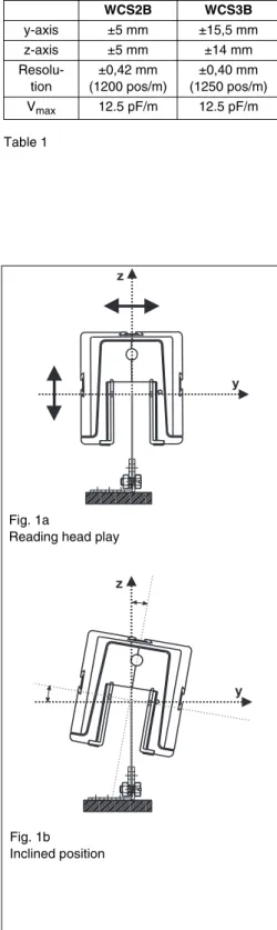
On the inside of the reading head there are easily replaceable, transparent plastic lin-ers to protect the reading area from dirt and damage (Fig. 2 and Fig. 3 on page 11). There are identification notches on these liners. Theese serve to set the zero point for vertical play (z-axis) on the reading head. The reference point is the top edge of the code rail. The reading head can move around the reference point within the spec-ified tolerances (see Table 1):
If the height play (z-axis) is exceeded, the reading head signals "OUT" (reading head outside of the code rail) to the control. The tolerances for lateral play (y-axis) are giv-en by the width of the gap in the reading head.
The positions are reliably detected in both vertical (α: ±10°) and horizontal (β: ±5°) inclined positions, and in bends down to a minimum of 500 mm. If positional value cannot be detected, e. g. because the optical elements are soiled, the reading head transmits a clear error code.
WCS2B/WCS3B
The reading heads were revised on the basis of the well-tried types WCS2A and WCS3A. The new type series was given the designation “B“, WCS2B and WCS3B. With the new black and green housing, the new reading heads integrate well into the design of the Pepperl+Fuchs sensors. The electric connection of the reading heads WCS2B and WCS3B is established exclusively by M12 plug connectors. A wide range of connecting sockets and pre-confectioned cables are available for these M12 plug connectors. The hardware and software for devices with SSI interfaces have been revised. Compared to the previous models, it is also new that the current speed can be transmitted to the control by the serial interface apart from the positional val-ue. Compared to the previous type WCS3A, a significant modification in the WCS3B reading heads is that the gap width has been enlarged at identical external dimen-sions. Due to the free space between the reading head and the code rail which has been increased by 25 per cent, the potential mechanical tolerances in the applica-tions are compensated automatically by the reading head. In addition to the previous-ly integrated interfaces, the CANopen interface is now offered for the WCS3B reading head as well.
Replacement of previous reading head types by WCS2B/WCS3B reading heads
The replacement of a reading head of type WCS2 or WCS2A by a WCS2B or a WCS3 or WCS3A by a WCS3B is possible. The important factor is that the type code is identical, such as LS221. If the reading head to be replaced has no M12 plug con-nection, the electrical connection had to be adapted to the M12 plug connection of the WCS2B/3B reading head. The manufacturer recommends the modification of the socket on the data cable present. The M12 cable socket required can be obtained from Pepperl+Fuchs as an accessory. If the modification of the plug connection on the data cable is not possible or desirable, corresponding adapter cables can be sup-plied.
An overview of the recommended M12 cable sockets and adapter cables is rendered in section "Data cables and accessories" on page 48 et seqq.
Table 1 WCS2B WCS3B y-axis ±5 mm ±15,5 mm z-axis ±5 mm ±14 mm Resolu-tion ±0,42 mm (1200 pos/m) ±0,40 mm (1250 pos/m) Vmax 12.5 pF/m 12.5 pF/m y z y z Fig. 1a
Reading head play
Fig. 1b Inclined position
Da te o f issu e: 1 6 . Ma y 20 07
WCS Reading Head
WCS2B reading head WCS3B Reading Head 129 10 75 40 38 33 75 115 57 M12 x 1B
Fig. 2Position of code rail with respect to reading head
Electric connection plug must point towards ascending positional values!
53 40.5 99 78.5 55 90 128 115 31 M12 x 1
3
B
Fig. 3 NoteDa te o f issu e: 1 6 . Ma y 20 07
12
WCS Reading Head
Subject to reasonable modifications due to technical advances. Copyright Pepperl+Fuchs, Printed in Germany Pepperl+Fuchs Group • Tel.: Germany +49 621 776-0 • USA +1 330 4253555 • Singapore +65 67799091 • Internet http://www.pepperl-fuchs.com
Installation of reading head
The reading head is generally fitted to the vehicle. However it is also possible to install the reading head in a stationary po-sition and attach a section of code rail to the vehicle (vehicle identification).
A special mounting plate is part of the supply of the reading head. This is attached to the vehicle. If the WCS2 is used with the aluminium profile system and guide trolley, the mounting plate is already integrated into the guide trolley. There are dovetail guides with a quick-action lock on three sides of the reading head housing. Using one of these guides as required, the reading head is snapped into place on the guide bar. Us-ing one of these guides as required, the readUs-ing head is snapped into place on the guide bar. Thanks to this quick-ac-tion lock, the reading head can be installed very simply with-out any adjustment, and replaced quickly if required.
The reading head can be installed in any position. It is tough and will function reliably even in a rugged industrial environ-ment. The reading head is not vulnerable to external light sources. During plant project work, it is recommended to en-sure that no strong sunlight directly enters the reading head gap.
To ensure long-term fault-free functioning, we recommend ensuring during installation that the gap in the reading head is protected from dirt and any vapours. The reading head must be fitted so that the electric connector plug points in direction of the ascending positional values on the code rail.
Spring tongue
Mounting plate
Groove Quick action lock
Da te o f issu e: 1 6 . Ma y 20 07
WCS Reading Head
Mounting plateThe mounting plate is attached to the vehicle with M4 screws. When designing the system, we recommend providing oblong holes to enable the position of the mounting plate and thus the reading head to be corrected. For installation, the dovetail groove of the reading head pushed over the bar on the mount-ing plate until the sprmount-ing tongue snaps into place.. To remove
the reading head, the spring tongue is released by turning slightly with a screwdriver and the reading head pushed out of the guide.
The mounting plate is for all reading head types identical.
Replacement of plastic liners
The plastic liners of the reading head can be replaced quickly if they are damaged or soiled. Unscrew the two cross-head screws on each liner and pull off the liner. Fit in reverse order. The cross-head screws must be tightened with a max. torque of 0.5 Nm. It is recommended to always replace both liners and also replace the seal.
The plastic liners are available as a spare part. WCS2B reading head:
2 plastic liners with seal: WCS2-PL2 WCS3B reading head:
Da te o f issu e: 1 6 . Ma y 20 07
14
WCS2/WCS3 code rail
Subject to reasonable modifications due to technical advances. Copyright Pepperl+Fuchs, Printed in Germany Pepperl+Fuchs Group • Tel.: Germany +49 621 776-0 • USA +1 330 4253555 • Singapore +65 67799091 • Internet http://www.pepperl-fuchs.com WCS2/WCS3 code rail
Code rail
The code rail, which carries the absolute code, differs for the WCS2 and the WCS3 and thus cannot be interchanged be-tween the two systems. In the case of the WCS3, the height of the code rail is always 70 mm, for the WCS2 the code rail can be supplied 55 mm or 70 mm high. Two different materials which have proven their suitability in practice are available for the code rail:plastic laminate and stainless steel. The code rail is supplied in a coil. Unless ordered otherwise, the code rail always begins with a positional value of 0.
Laminate code rail
The black laminate code rail is made of a special polyester laminate. It is distinguished by excellent physical and chemi-cal characteristics with a low deadweight. The material is highly resistant to rupture, and is neutral with respect to oils, greases and solvents. Thanks to its resistance to acids, lyes and aggressive gases, this material is also suitable for use in galvanising plants. As a standard feature the laminate code rails are supplied with mounting holes (WCS3-CS70-L1, also see the drawing below). If an angle system is used to mount code rails it is recommended to use code rails without mount-ing holes (WCS3-CS70-L0) as shown, for example, on page 16.
The laminate code rails can be used in a temperature range of between -40 °C and 60 °C. Temperatures higher than 70 °C will lead a deformation of the material. The specific coefficient of thermal expansion is approx. 2.8 x 10⁻⁵K-1. Due to the ma-terial properties, the laminate code rails must not be mounted when temperatures of 10 °C may occur. In case of applica-tions with larger temperature variaapplica-tions (> 50 K), we recom-mend the use of the stainless steel code rail.
Stainless steel code rail
The stainless steel code rail is manufactured in corrosion-re-sistant spring steel. It is rust-proof and displays high mechan-ical stability and low thermal expansion. The stainless steel code rails can be used within a temperature range of -40 °C ... 80 °C.
The specific thermal expansion coefficient is 1.6 x 10⁻⁵K-1. Protective gloves must be worn when installing the stainless steel code rails.
When mounting the laminate code rail, please make sure that grinding dust of collectors cannot fall on to the surface of the code rails directly. For this reason, the laminate code rails should be mounted laterally above the contact lines. Attention
Dimensions [mm]
a b c
Band 55 x 0.5 55 7.5 25
Band 70 x 0.5 70 15 41
WCS2 code rail Six-figure item number
Da te o f issu e: 1 6 . Ma y 20 07
WCS2/WCS3 code rail
Grounding of code rail
During the installation of the laminate or stainless steel WCS code rail, please ensure that it is connected to a low-ohmic po-tential at a distance of at least every 30 m.
Tensioning device for the stainless steel code rail
Using the tensioning device prevents the stainless steel code rails buckling due to temperature fluctuations after installation. It also facilitates installation. Three holes are punched at the beginning and at the end of the stainless steel rail and can be
used to attach the tensioning device.
There are two possibilities when using the tensioning device: 1. The code rail is fixed at one end and tensioned at the
oth-er end using the tensioning device.
2. The code rail is fixed in the middle and tensioned at both ends using the tensioning device. The method is of ad-vantage for longer sections (> 50 m).
ID-Pads WCS3-ID70-M1
In applications where the vehicle numbers in the system have to be recognized, special code rail segments, so-called ID pads, are available for the WCS3 system. In case of these ap-plications, the reading head is firmly mounted in most cases, and the ID pads mounted to the vehicle the reading head at certain points in the system.
The positional value read by the reading head is then used by the control to calculate the integer vehicle number according
to a formula. In total, 1,260 different ID pads can be supplied Vehicle number = INT((WCS positional value 30)/312)+1 The position value determined by the reading head enables the fine positioning of the ID pad in the reading head gap, apart from the calculation of the vehicle number, and thus an exact positioning of the vehicle.
Mounting the code rail
If continuous path measurement of a distance is required, the rail has to be mounted in one piece. Independent of the con-ditions of use, there a plenty of possibilities of mounting the code rails, basically. The easiest possibility to mount the code
rail is to screw it down to a suitable angle. During the installa-tion, please make sure that the tolerance in vertical and hori-zontal direction is observed as required by the respective reading head.
Stainless steel code rail Torque
WCS2, 55 mm 6 nm WCS2, 70 mm 9 nm WCS2, 70 mm 7 nm Tensioning device WCS-MT1 70 7.5 6.5 12 240 ... 264 19.2 192 19.2 57.5 25.5 XXXX = 0001 ... 1260 XXXX
Mounting bracket system for WCS code rail
Subject to reasonable modifications due to technical advances. Copyright Pepperl+Fuchs, Printed in Germany Pepperl+Fuchs Group • Tel.: Germany +49 621 776-0 • USA +1 330 4253555 • Singapore +65 67799091 • Internet http://www.pepperl-fuchs.com
Da te o f issu e: 1 6 . Ma y 20 07
16
Mounting bracket system for WCS code rail
Mounting the code rail with the mounting bracket system
The angle system is one possibility to mount the laminate or stainless steel code rail. It consists of brackets for installing straight sections (Fig. 1) of the code rail, and brackets for installing the code rail in bends and on circular runways (Fig. 5). The brackets are made of galvanised steel plate and supplied pre-assembled.
The mounting brackets for the installation of the WCS code rail on straight distances can be supplied in three different designs:
WCS-MB: angle for straight section without fixing screws (Fig. 1) WCS-MB1: angle for straight section with fixing screws (Fig. 2)
WCS-MB2: angle for straight section with mounting system for installation in C profile rail 30 x 32 mm (Fig. 3).
The mounting brackets for installing straight sections are fitted to the substructure at intervals of max. 1.25 m along the runway. The code rail is pushed into the bracket until it makes contact. Subsequently the code rail is slightly tensioned by pulling and tightening of the two hexagonal screws (M6 x 12) in the angle. The torques for these hexagonal screws (M6 x 12):
• for laminate code rail: max. 8 Nm • for stainless steel code rail: max. 5 Nm
The code rail is tensioned by pulling at the free end. The counternuts of the screws are pressed into the angle sheet which means that the nuts need not be countered. Given correct mounting, the tensioning force on the angles to high that the code rails cannot be pulled out of the angle any more.
In addition to the clamping action, the code rail can be screwed down to the angle. For this purpose, use the two upper free boreholes of the angle (M6). The screw con-nection produces a reference point between the code rail and the subconstruction. The screws for the reference point do not belong to the scope of delivery.
The use of C profiles is advantageous for angle mounting. They are arranged longi-tudinally or transversely to the travel intended. Thus, the angles can be mounted and aligned easily in the C profiles.
Powder-coated version
The mounting bracket for straight sections is also available in a powder coated ver-sion. In this version, the fixing screws are stainless steel (high grade steel V4A). Two different variants can be supplied:
WCS-MB-C Powder-coated angle for straight laying without fixing screws WCS-MB2-C: powder-coated angle for straight laying with mounting system for
installation in C profile rails 30 x 32 mm.
Fig. 1
Mounting bracket straight section (WCS-MB)
Fig. 2
Screw-on mounting bracket, straight section (WCS-MB1)
Fig. 3
Mounting bracket for C profile straight section (WCS-MB2)
max. 1.25 m max. 1.25 m
Fig. 4
Da te o f issu e: 1 6 . Ma y 20 07
Mounting bracket system for WCS code rail
Bend
To produce bends, the mounting brackets for bends (bend brackets, Figs. 5 and 6) are used together with a special stabilising profile (WCS-SP2). The stabilising profile is supplied as a coil of the length ordered.
The mounting brackets for installation of the WCS code rail on curved distances can be supplied in three different designs:
WCS-MB-B Mounting bracket for bend without fixing screws (Fig. 5) WCS-MB1-B: Mounting bracket for bend with fixing screws
WCS-MB2-B: Mounting bracket for bend with mounting system for installation in C profile rail 30 x 32 mm (Fig. 6).
The curved angle has been designed in such a way that no height or transverse offset of the code rail occurs when the straight stretch changes into the curve.
The curve angles are mounted tangentially along the circle / curve bend; maximum support distance 0.7 m (0.5 m recommended). Subsequently the stabilization profile is cut to the length of the curve bend and is laid into the curve angle. The code rail is now pressed right into the groove of the stabilization profile. Subsequently, the clamping screws (M4; hexagon socket) is used to clamp the code rail together with the stabilization profileinto the curve angle, where the cutting screw supplied is used for locking.
Circuit
Given a closed route (circuit, oval, et cetera), the following special features have to be observed:due to the functions of the WCS, the code rail cannot be laid on the whole circuit. A distance of least 85 mm has to be kept between the beginning and the end of the code rail. At the interrupted point of the code rail, the control will receive the value "OUT" - reading head outside of the code rail" from the reading head. When using two reading heads mounted after each other at a distance, continuous travel information is possible at all positions of the circuit. In this case the control switches over to the position value of the second reading head when the "OUT" message has been received.
Installation position of code rail
The code rail can be installed in any position desired (see Fig. 7). When installing the code rail, care must be taken that all the mounting brackets are installed at the same level, i. e. the surface on which the brackets are installed must be flat.
Fig. 5
Mounting bracket, bend (WCS-MB/B)
Fig. 6
Mounting bracket for C profile, bend (WCS-MB2/B) Fig. 7 Installation positions of code rail Stabilising profile Torque: 4 nm (a) (b) (c) (d) Fig. 8
Application example for mounting bracket, straight section and bend
a: Mounting bracket b: Curve angle c: Stabilizing profile d: Code rail R: Curve radius a a a b b c c d d
Da te o f issu e: 1 6 . Ma y 20 07
18
Mounting WCS2 code rails with aluminium profile system
Subject to reasonable modifications due to technical advances. Copyright Pepperl+Fuchs, Printed in Germany Pepperl+Fuchs Group • Tel.: Germany +49 621 776-0 • USA +1 330 4253555 • Singapore +65 67799091 • Internet http://www.pepperl-fuchs.com Mounting WCS2 code rails with aluminium profile system
Mounting WCS2 code rails with aluminium profile system
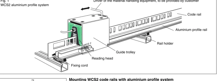
A special aluminium profile system has been developed for fast mounting of the 55 mm code rail made of plastic laminate or stainless steel. The aluminium profile has been designed in such a way that it takes the code rail and the guide trolley. The guide trolley ensures the ideal position of the reading head relative to the code rail and compensates the travel tolerances between the vehicle and the WCS system. At the same time the reading head is decoupled from the vehicle vibrations. The aluminium profile system can be mounted in any position. The profile rails are supplied in segments of 5 m in length and have been provided with a 45 deg. miter at the ends. The aluminium profile rails can be supplied with a powder coating and in curved segments.
Mounting the aluminium profile rail
For mounting the aluminium profile rail, rail holders are available for fast mounting, in which the profile rail snaps in. The rail holders can be supplied in three different vari-ants:
WCS2-MH: Rail holder without fixing screws WCS2-MH1: Rail holder with fixing screw (Fig. 4)
WCS2-MH2: Rail holder with mounting system for installation in C profile rail 30 x 32 mm (Fig. 5).
The suspension distance for the aluminium profile rail must not exceed 1.5 m (min. 3 rail holders per 5 m section) for both upright and suspended mounting.
If the WCS2 aluminium profile system is mounted laterally, a support spacing of 1.25 m (four rail holders per rail of 5 meters in length) is recommended.
Driver of the material handling equipment, to be provided by customer
Code rail
Aluminium profile rail
Rail holder Guide trolley
Reading head Fixing cord
Fig. 1
WCS2 aluminium profile system
24 11 8 ,5 32 2 79 68 147 65,3 92 Fig. 2
Aluminium profile system WCS2 with C pro-file rail
Fig. 3
Mounting rail holder
Fig. 4 Screw-on holder 1 rail holder 2 M6 x 30 cheese-head screw 3 M6 hex. nut 4 spring washer 1 2 3 4 Fig. 5
Holder for C profile WCS-MH2 1 rail holder 2 M6 x 20 cheese-head screw 3 square nut 30 x 25 mm, M6 4 washer R 6.6 1 2 3 4
Da te o f issu e: 1 6 . Ma y 20 07
Mounting WCS2 code rails with aluminium profile system
Connectors for aluminium profile rails
Connectors are necessary for joining the aluminium profile rails. Each connector (WCS-MC1) consists of two flat aluminium pieces and four self tapping screws (3 mm x 4.5 mm). The flat pieces are pushed into the bottom grooves in the two pro-file rails to be joined, with drillholes ahead. Then the screws will screwed into the holes of the flat pieces (see drawing at left side). The tips of the screwes will pressed into the aluminium profile and fix the flat pieces in the grooves.
Note: The rail connection must be screwed down on one side only (see Fig. 6). Stainless steel connectors are used for joining the powder-coated aluminium profile rails (WCS-MC2).
Notes on installing the aluminium profile rail
When assembling the aluminium profile rails with the connectors, it is important to leave a gap to compensate for thermal expansion in case the temperature maximum operating temperature possible should be higher than the temperature during instal-lation. The gap width necessary is calculated as follows:
Gap width in mm = 0.11 * ∆ϑ
∆ϑ = ϑmax. operationϑinstallation Examples:
∆ϑ = 10 K, gap width = 1.1 mm
∆ϑ = 20 K, gap width = 2.2 mm
∆ϑ = 30 K, gap width = 3.3 mm
Installing the code rail in the profile rail
First of all, aluminium profile rail is attached to the substructure using the rail holders and aligned. The joints must be produced as described. Then the code rail can be laid fully in the groove of the profile rail. The code rail is ultimately fixed by means of a plastic cord which is pressed into the groove of the profile rail. To do so, the cord is pressed into the groove while simultaneously pressing down the code rail. Press-ing it in correctly is extremely important for reliable operation, in particular if the alu-minium profile system is suspended.
Fig. 6
Joint (WCS2-MC1), view from below
Fig. 7
Installation of connector
Fig. 8
Assembling aluminium profiles
Fig. 9
Mounting WCS2 code rails with aluminium profile system
Subject to reasonable modifications due to technical advances. Copyright Pepperl+Fuchs, Printed in Germany Pepperl+Fuchs Group • Tel.: Germany +49 621 776-0 • USA +1 330 4253555 • Singapore +65 67799091 • Internet http://www.pepperl-fuchs.com
Da te o f issu e: 1 6 . Ma y 20 07
20
Fitting toolA special fitting tool is available for speedy and safe installation of the code rail. The fitting tool is to be recommended particularly if the aluminium profile system is sus-pended. The tool consists of a housing with wheels similar to the guide trolley. The trolley is pulled along the profile rail. The code rail is held in position by the guide roller and pressure roller and the fixing cord pressed into the groove of the aluminium pro-file by the pressing wheel. Moving the trolley back and forth ensures that the plastic cord sits in the groove correctly (Fig. 10). If it is installed correctly, the pressure of the fixing cord is only sufficient to prevent the code rail slipping out of the aluminium pro-file even if it is in a suspended position.
The seating of the plastic cord and the code rail should be checked during mainte-nance, in particular if the aluminium profile is suspended.
Fixed points
To prevent the aluminium profile rails slipping in the rail holders when installed hori-zontally, a locking bracket is necessary. The locking bracket (Fig. 11) is fitted around a rail holder in the middle of the runway. During installation, bracket and aluminium profile are joined with the screw supplied. To do this, the aluminium profile must be drilled through at one point (drill 7 mm). If installed vertically, we recommend locking the aluminium profile with a suitable support bracket (by customer). To prevent the code rail slipping in the aluminium profile, it can be fixed in the centre of the runway by inserting a spring dowel pin or self-tapping screw (Fig. 12).
Guide trolley
The guide trolley (Fig. 13 and 14) for the reading head always ensures optimum po-sition of the reading head in relation to the code rail. The mounting plate for the read-ing head is already prefitted on the trolley so that it only needs to be pushed on. By means of the towing arm moving freely in the oblong hole of the guide trolley (8 mm in diameter), on the one hand the movement between vehicle and reading head is isolated, and on the other hand mechanical tolerances are equalised. When fitting the towing arm installed on the conveyor vehicle, take care that no forces are exerted (no rigid connection between towing arm and guide trolley!). On the guide trolley holes are provided for fitting the cleaning brushes for the code rail (WCS2-GTBR). The cleaning brushes (optional extra) are only necessary, if the code holes in the WCS code rail may be clogged during to the application, such as by leaves or bird feathers. The brushes can be retrofitted. In dusty environments, such as in foundries or in the building materials industry, we recommend the use of guide trolleys fitted with metal rollers (WCS2-GT09-M1).
If the WCS2 aluminium profile system is mounted laterally, the use of the guide trolley with extended guide rails (WCS2-GT09-P2 or WCS2-GT09-M2) is recommended. The maximum velocity for the reading head with guide trolley is 8 m/sec. The guide trolley is also available powdercoated (WCS2-GT09-P1-C).
Note: Push the guide trolley with the reading head into the profile rail in such a way that the electric plug connector points in the direction of the ascending positional val-ues.
ø 8 mm Fig. 10:
Fitting tool for code rail (WCS2-FT1)
Fig. 11:
Locking bracket for aluminium profile (WCS-LB1)
Fig. 12:
Fixed point for code rail
Fig. 13:
Da te o f issu e: 1 6 . Ma y 20 07
Mounting WCS2 code rails with aluminium profile system
Grounding the aluminium profile
The aluminium profile must be connected up to the low-ohmic potential at a distance of at least every 30 meters (Fig. 15).
Further information
Stainless steel or laminate code rails can be used with the aluminium profile system. The laminate code rail has proved to be suitable for normal industrial applications. In addition to cost advantages, the plastic laminate code rail is of advantage during in-stallation, in particular on long runways, due to its lighter weight.
For extreme operating conditions, e. g. sparking in a welding shop, severe dirt accu-mulation during operation (e. g. waste incineration) or if cleaning brushes are used on the guide trolley, we recommend using the stainless steel code rail.
Pre-tensioning the code rail is not necessary for the system functions. This It is mere-ly useful if high temperature fluctuations may occur within short periods of time.
For more information and instructions on the installation of the WCS2 aluminium pro-file system, please refer to our website on the Internet at http://www.pepperl-fuchs.com.
The tensioning device can only be used in conjunction with the stainless steel code rai (p.15).
Fig. 14:
WCS2 guide trolley for reading head (WCS2-GT09-P1)
Fig. 15:
Grounding aluminium profile
Installation of WCS3 code rail with aluminium profile system
Subject to reasonable modifications due to technical advances. Copyright Pepperl+Fuchs, Printed in Germany Pepperl+Fuchs Group • Tel.: Germany +49 621 776-0 • USA +1 330 4253555 • Singapore +65 67799091 • Internet http://www.pepperl-fuchs.com
Da te o f issu e: 1 6 . Ma y 20 07
22
Installation of WCS3 code rail with aluminium profile system
Installation of WCS3 code rail with aluminium profile system
A special aluminium profile system has been developed for the rapid installation of the 70 mm high WCS3 code rail in plastic laminate or stainless steel. The aluminium profile is designed to take the code rail. It has been designed to provide optimum flex-ural strength in all directions in spite of its low weight. The aluminium profile system can be fitted in any position. The profile rails are supplied in 6 m sections.
On request, the aluminium profile rail can also be supplied powder-coated and in curved sections.
Installing the aluminium profile rail
Rail holders, into which the profile rail is clipped, are available for rapid installation of the aluminium profile rail. The rail holders are available in three different versions: WCS3-MH: Rail holder without mounting screws
WCS3-MH1: Rail holder with mounting screw (Fig. 5)
WCS3-MH2: Rail holder with mounting system for installation in C profile rail 30 x 32 mm (Fig. 6).
The recommend spacing is 2.00 m (three rail holder per 6 meter segment); the max-imum spacing between supports is 2.50 m.
Rail connectors for aluminium profile rails
Connections are necessary for joining the aluminium profile rails. Each connector (WCS3-MC1) consists of a 170 mm long aluminium extruded section and two selftap-ping screws M3 x 4.5 mm. The connector is pushed into the bottom grooves in the two profile rails to be joined. Then the screws are screwed into the holes (1.8 mm in diameter), see Fig. 7. The tips of the screws are pressed into the aluminium profile and hold the connector down.
Note: The rail connection may be screwed down on one side only (see Fig. 7).
Holder on vehicle by customer
Code rail Mounting plate
Fixing cord
Rail holder
Aluminium profile rail Reading head Fig. 1
WCS3 aluminium profile system
˚
M12 Fig. 2
Aluminium profile system WCS3 (WCS3-PS1)
Fig. 3
Aluminium profile system WCS3 with C profile rail
Fig. 4
Installation the rail holder
Fig. 5 Screw-on holder WCS3-MH1 1 - rail holder 2 - M6 x 30 cheese-head screw 3 - M6 hex. nut 4 - A6 spring washer 1 4 2 3
Da te o f issu e: 1 6 . Ma y 20 07
Installation of WCS3 code rail with aluminium profile system
Installation of WCS3 code rail with aluminium profile system
Notes on installing the aluminium profile rail
When assembling the aluminium profile rails with the connectors, it is important to leave a gap to compensate for thermal expansion. This is necessary if the maximum operating temperature possible should be greater than the temperature during instal-lation. The gap width necessary is calculated as follows:
Gap width [mm] = 0.12 * ∆ϑ
∆ϑ = ϑmax. operation -ϑinstallation Examples:
∆ϑ = 10 K, gap width = 1.2 mm
∆ϑ = 20 K, gap width = 2.4 mm
∆ϑ = 30 K, gap width = 3.6 mm
Grounding the aluminium profile system
The aluminium profile must be connected up to the low-ohmic potential at a distance of at least every 30 meters (see Fig. 15 on page 21).
Installing the code rail in the profile rail
First of all, the aluminium profile rail is attached to the substructure using the rail hold-ers and aligned. The joints must be produced as described. Then the code rail can be laid fully in the groove of the profile rail. The code rail is ultimately fixed by means of a plastic cord which is pressed into the groove of the profile rail. To do so, the cord is pressed into the groove while simultaneously pressing down the code rail. Pressing it in correctly is extremely important for reliable operation, in particular if the alumini-um profile system is suspended.
Fitting tool
A special fitting tool is available for secure and speedy attachment of the code rail. It is particularly recommended if the aluminium profile system is suspended. The tool consists of a wheeled housing. The trolley is pulled over the profile rail, the code rail being held in position by the guide roller and the fixing cord pressed into the groove of the aluminium profile by the pressing wheel. Moving the mounting trolley back and forth ensures that the fixing cord lies correctly in the groove of the aluminium profile (Fig. 10). If fitted correctly, the pressure from the fixing cord is sufficient to prevent the code rail slipping out of the aluminium profile even when suspended.
The seating of the fixing cord and cord rail must be checked during maintenance, par-ticularly if the aluminium profile is suspended.
Fig. 6
Holder for C profile WCS3-MH2
1 - rail holder 2 - M6 x 20 cheese-head screw 3 - square nut 30 x 25 mm, M6 1 2 3 Fig. 7 Installation of connector Fig. 8
Assembling aluminium profiles
Fig. 9
Installation of WCS3 aluminium profile
Fig. 10:
Fitting tool for code rail (WCS3-FT1)
Installation of WCS3 code rail with aluminium profile system
Subject to reasonable modifications due to technical advances. Copyright Pepperl+Fuchs, Printed in Germany Pepperl+Fuchs Group • Tel.: Germany +49 621 776-0 • USA +1 330 4253555 • Singapore +65 67799091 • Internet http://www.pepperl-fuchs.com
Da te o f issu e: 1 6 . Ma y 20 07
24
Fixed pointsTo prevent the aluminium profile rails slipping in the rail holders when installed hori-zontally, the profile must be firmly connected to the substructure. A rail holder in the centre of the runway is rough-drilled on both sides with a drilling 1.8 mm in diameter (Fig. 11). Self-tapping screws (3 x 6 mm) are screwed into these drillings. The self-tapping screws are not supplied. The screws press into the aluminium profile forming a keyed connection (Fig. 12) between rail holder and aluminium profile. We recom-mend to fix the aluminium profile as described at several points along a runway. An adequate expansion joint between the aluminium profiles must be ensured (see also page 23).
If installed vertically, we recommend locking the aluminium profile with a suitable sup-port bracket (by customer).
Vertical bend
Beside horizontal bends, also vertical bends are needed, to realize upward/down-ward gradients. With the help of the aluminium profile rail, together with the laminate code rail, vertical bends up to a minimum radius of 4 m can be made very simply. For this, the aluminium profiles bent with the appropriate radius are clipped into the rail holders. To ensure that the code rail can follow the vertical course of the bend, a cut is made from the start of the bend up to its end, in the distance of approx. 50 mm. The cuts are always made from below, i. e. from the wider side of the code rail until into the code windows (see Fig. 13). In addition, a small triangle is cut off with every cut (see Fig. 14). This prevents the code rail from overlapping in the aluminium pro-file.
If the code rail was cut as described, it is inserted together with the fixing cord and by means of the fitting tool into the pre-curved aluminium profile.
Fig. 15: Vertical bend
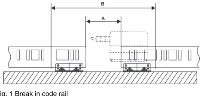
Breaks in aluminium profile
For some applications, it may be necessary to interrupt the code rail, e. g. for crane crossovers, fire doors or large expansion joints in buildings. The break in the code rail must be at least 85 mm and the two code rail sections must be aligned. The maximum clearance between the end of an aluminium profile rail and the next rail holder must not exceed 0.5 m. Fig. 11: Fixed point Fig. 12: Fixed point Fig. 13:
Cutting code rail edge
Fig. 14:
Da te o f issu e: 1 6 . Ma y 20 07
Integrating WCS3 code rail into Vahle VKS 10 power rail
Integrating WCS3 code rail into Vahle VKS 10 power rail
Suspension of stainless steel code rail
When the stainless steel code rail is suspended, in particular if there are frequent temperature fluctuations, it must be secured against falling. Using the tensioning de-vice is sufficient for lengths up to approx. 25 m. Above this, we recommend securing the stainless steel code rail in the aluminium profile every 12 m with a self-tapping screw or a spring dowel pin. The aluminium profile and the code rail are through-drilled from the side (see Fig. 16). Then the self-tapping screw is screwed into this drilling (or the dowel pin pressed in). The self-tapping screw or dowel pin are not sup-plied.
Further information
The stainless steel or laminate code rails can both be used with the WCS3 aluminium profile system. The laminate code rail has proved to be suitable for normal industrial applications. In addition to cost advantages, the plastic laminate code rail is of advan-tage during installation, in particular on long runways, due to its lighter weight. With regard to operating conditions, the same applies as for the WCS2 profile system (see p. 18), with one exception: a guide trolley is not used in conjunction with the WCS3 aluminium profile system.
You will find further information and installation hints in "WCS3 special aluminium profile system". This document can be requested from us or downloaded from our In-ternet home page.
Integrating WCS code rail into conductor lines
In many applications, energy is transmitted to a vehicle by means of conductor lines. Users often request an integrated solution for energy transmission and positional measurement. This demand has been taken into account in developing the new Vah-le VKS 10 power rail. The VKS 10 is fVah-lexibVah-le as regards the number and cross-sec-tions of conductors and enables the WCS code rail to be integrated economically into the plastic base of the conductor line. Special holes for installation, and thus a special code rail, is necessary for installing the WCS3 code rail in the VKS10 system (WCS3-CS70-L2).
The laminate code rail is characterised by high flexibility and tear resistance. Repro-ducibility of location coordinates is guaranteed by the use of the code rail, indepen-dent of the ambient conditions. Reproducibility of location coordinates is guaranteed by the use of the code rail, independent of the ambient conditions.
Grounding the code rail
If During the installation of the WCS code rail in the VKS10 system, the code rail has to be connected to a low-ohmic plant potential at distance of at least every 30 meters. You can obtain further information on the VKS 10 conductor line system from the Vahle sales organisation. You will find the relevant sales office at www.vahle.de.
Fig. 16:
Topdown assembly
WCS3B-Lesekopf WCS3-CS70-L2
Fig. 17:
Integration of WCS3 code rail into Vahle VKS 10 power rail
Da te o f issu e: 1 6 . Ma y. 20 07
26
Electric connection of WCS reading head with RS485 interface
Subject to reasonable modifications due to technical advances. Copyright Pepperl+Fuchs, Printed in Germany Pepperl+Fuchs Group • Tel.: Germany +49 621 776-0 • USA +1 330 4253555 • Singapore +65 67799091 • Internet http://www.pepperl-fuchs.com Electric connection of WCS reading head with RS485 interface
Connection of WCS reading head to control
The WCS2B and WCS3B reading heads are available in dif-ferent interface versions: RS 485 interface and SSI interface (serial synchronous interface). The WCS3B reading head is available also with an integrated CANopen interface.
Reading head with RS485 interface
The reading head can be connected directly to the control via a serial RS 485 interface. Various data protocols and data transmission rates are available. Up to four WCS2B and/or WCS3B reading heads can be connected together in an RS 485 bus line. In this case, the reading heads must have differ-ent bus addresses. The bus address for the reading head, if it has not been preset, has to be configured in the reading head. The configuration instructions can be downloaded from the In-ternet website. The reading head address has been preset al-ready, this is indicated by the type designation of the reading head (type plate on the reading head). Please also see pages 44 and 51.
Type of reading head
The reading head type is given by the RS 485 terminating re-sistor, baud rate and data protocol.
Example: LS221-1 means:
2 ... reading head with RS485 terminating resistor 2 ... baud rate 62.5 kBaud
1 ... data protocol 1 and 2 1 ... reading head address 1
See also types summary on page 51.
Electric connection of the WCS2B reading head with RS 485 interface
The electrical connection of the WCS2B reading head is via a 5-pole M12 plug.
Electric connection of WCS3B reading head with RS 485 interface
The electrical connection of the WCS2B reading head is via a 5-pole M12 plug.
*) Speed output in reading heads with option S (see p. 30). The counter-piece of the plug connector, the 5-pole M12 sock-et, is not part of the supply of the reading head.
Different pin configurations in WCS2B and WCS3B read-ing heads
The configuration of the plug connector of the WCS2B is com-patible with the WCS2 and WCS2A reading head.
The WCS3B reading head is the first reading head in the WCS3 type series with an M12 plug connector. The configu-ration of the M12 connector in the WCS3B reading head is thus in keeping with the M12 standard configuration for sen-sors.
For electrical connection, we recommend confectioned M12 cable sockets or shielded data cable with attached M12 cable sockets provided by Pepperl+Fuchs (see section "Data cables and accessories" on page 48).
The WCSB reading heads have no connection possibilities for the cable shield, either on the plug connector or on the read-ing head housread-ing. A low-resistance (wide area) connection between the cable shield and the system potential is made in the control panel. In the case of high electromagnetic interfer-ence radiation, it is recommended to make a low-resistance connection between the shield of the data cable and the sys-tem potential by an earthing clamp in the direct vicinity of the reading head. WCS2B, RS 485 interface Pin Designation 1 RS 485 -2 UB+ 3 GND 4 RS485 + 5 n. c. WCS3B, RS 485 interface Pin Designation 1 UB+ 2 RS 485 + 3 GND 4 RS 485 -5 reserved *)
Da te o f issu e: 1 6 . Ma y. 20 07
Data protocols of WCS reading heads with RS485 interface
Data protocols of WCS reading heads with RS485 interface
Data protocols of WCS reading heads with RS485 inter-face
Various data protocols and data transmission rates are avail-able for the direct connection of the reading head to the prima-ry control via a serial communication channel. The data protocols and baud rates are identical for the corresponding types of both WCS2 and WCS3 reading heads.
A byte has the following format:
The control must always request the reading head to transmit. The data protocols can be selected independent of the baud rate.
The following baud rates are available: 187.5 kBaud: reading head type LS21x 62.5 kBaud: reading head type LS21x 38.4 kBaud: reading head type LS21x 31.25 kBaud: reading head type LS21x 19.2 kBaud: reading head type LS21x 9.6 kBaud: reading head type LS25x See also type summary page 51.
Data protocols 1 and 2 use the eighth data bit as a means of differentiating between request byte and response byte. Data protocol 3 is available for controls which do not support direc-tion control through the eighth data bit. Reading heads with RS485 interface and data protocol 3 can be supplied as type LSxx6 = data protocol 3 with parity (even parity), 9 bit/byte or as type LSxx7 = data protocol 3 without parity = 8 bit/byte.
Response times
The minimum response time of the reading head (start trans-mission of 1st data bytes of response telegram) is dependent on the internal time sequence of the reading head and is 10 ... 180 µsec for data protocols 1 and 2.
For data protocol 3, the response time is one byte time + 10 ... 100 µsec. The byte time is dependent on the baud rate and is calculated from 1/baud rate * 11,000 in µsec.
Example: 38.4 kBaud
Byte time = 1/38.4 * 11,000 = 286.5 µsec.
Data protocol 1
NEW: Protocol 1 with position and velocity output
Data protocol 2
NEW: Protocol 2 with position and velocity output
Data protocol 3
NEW: Protocol 3 with position and speed output
Explanation of data bits, see p. 43.
Request byte to reading head
Bit 8 7 6 5 4 3 2 1 0
1 0 0 0 F0 0 0 A1 A0
Response telegram from reading head
Bit 8 7 6 5 4 3 2 1 0
Byte 1 0 OUT Err A1 A0 DB P18 P17 P16
Byte 2 0 P15 P14 P13 P12 P11 P10 P09 P08
Byte 3 0 P07 P06 P05 P04 P03 P02 P01 P00
Byte 4 0 OUT Err A1 A0 DB P18 P17 P16
Byte 5 0 P15 P14 P13 P12 P11 P10 P09 P08
Byte 6 0 P07 P06 P05 P04 P03 P02 P01 P00
0 1 2 3 4 5 6 7 8
Request byte to reading head
Bit 8 7 6 5 4 3 2 1 0
1 1 0 0 0 0 0 A1 A0
Response telegram from reading head
Bit 8 7 6 5 4 3 2 1 0
Byte 1 0 OUT Err A1 A0 DB P18 P17 P16
Byte 2 0 P15 P14 P13 P12 P11 P10 P09 P08
Byte 3 0 P07 P06 P05 P04 P03 P02 P01 P00
Byte 4 0 SST SP6 SP5 SP4 SP3 SP2 SP1 SP0
Byte 5 0 OUT Err A1 A0 DB P18 P17 P16
Byte 6 0 P15 P14 P13 P12 P11 P10 P09 P08
Byte 7 0 P07 P06 P05 P04 P03 P02 P01 P00
Byte 8 0 SST SP6 SP5 SP4 SP3 SP2 SP1 SP0
Request byte to reading head
Bit 8 7 6 5 4 3 2 1 0
1 0 1 1 F0 0 0 A1 A0
Response telegram from the reading head
Bit 8 7 6 5 4 3 2 1 0
Byte 1 0 OUT Err A1 A0 DB P18 P17 P16
Byte 2 0 P15 P14 P13 P12 P11 P10 P09 P08
Byte 3 0 P07 P06 P05 P04 P03 P02 P01 P00
Byte 4 0 Exclusive or coupling byte 1 ... byte 3
Request byte sent to reading head
Bit 8 7 6 5 4 3 2 1 0
1 1 1 1 0 0 0 A1 A0
Response telegram from reading head
Bit 8 7 6 5 4 3 2 1 0
Byte 1 0 OUT Err A1 A0 DB P18 P17 P16
Byte 2 0 P15 P14 P13 P12 P11 P10 P09 P08
Byte 3 0 P07 P06 P05 P04 P03 P02 P01 P00
Byte 4 0 SST SP6 SP5 SP4 SP3 SP2 SP1 SP0
Byte 5 0 Exclusive OR linkage Byte 1 ... Byte 4
Request byte to reading head
Bit 8 7 6 5 4 3 2 1 0
PAR 1 0 0 F0 0 0 A1 A0
Response telegram from reading head
Bit 8 7 6 5 4 3 2 1 0
Byte 1 PAR 0 0 A1 A0 0 DB OUT Err
Byte 2 PAR 0 0 0 P18 P17 P16 P15 P14
Byte 3 PAR 0 P13 P12 P11 P10 P09 P08 P07
Byte 4 PAR 0 P06 P05 P04 P03 P02 P01 P00
Byte 5 PAR Exclusive or coupling byte 1 ... byte 4
Request byte to reading head
Bit 8 7 6 5 4 3 2 1 0
PAR 1 1 1 0 0 0 A1 A0
Response telegram from reading head
Bit 8 7 6 5 4 3 2 1 0
Byte 1 PAR 0 SST A1 A0 0 DB OUT Err
Byte 2 PAR 0 0 0 P18 P17 P16 P15 P14
Byte 3 PAR 0 P13 P12 P11 P10 P09 P08 P07
Byte 4 PAR 0 P06 P05 P04 P03 P02 P01 P00
Byte 5 PAR 0 SP6 SP5 SP4 SP3 SP2 SP1 SP0
Da te o f issu e: 1 6 . Ma y. 20 07
28
Reading head with CANopen interface
Subject to reasonable modifications due to technical advances. Copyright Pepperl+Fuchs, Printed in Germany Pepperl+Fuchs Group • Tel.: Germany +49 621 776-0 • USA +1 330 4253555 • Singapore +65 67799091 • Internet http://www.pepperl-fuchs.com Reading head with CANopen interface
Reading head with CANopen interface
After configuration, the WCS3B reading head with CANopen interface can be connected directly to a CANopen bus. A DIP switch is used for configuration in deenergised state.
The CAN interface is galvanically separated. The reading head operates as a CANopen slave in "Predefined connection set" and sends data in TxPDO1 format.
Electrical connection
The connection is established via 5-pole M12 plug. The coun-terpiece of the plug connector is not part of supply of the read-ing head.
CAN terminating resistor
A simple DIP switch is located on the middle PCB in the read-ing head. This switch can be used to switch the 120 Ohm CAN terminating resistor on or off. In delivery condition, the termi-nating resistor has been switched on.
Baud rate
The baud rate can be changed by means of two switches of the 8 DIP switches located on the middle PCB in the reading head. In delivery condition, the baud rate has been set to 250 kBaud.
Node ID
The address in the CANopen bus, the node ID, can be changed by means of the switches 1 to 6 of the 8 DIP switches located on the middle PCB in the reading head. The node ID is coded in binary mode. The smallest possible node ID is 1; the highest possible node ID is 63; node ID 0 is not permitted. In delivery condition, the node ID has been set to 1.
Transmission mode in the CANopenbus
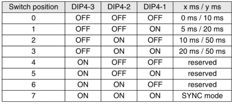
By means of three switches of the 4 DIP switches on the lat-eral PCB of the reading head, the transmission mode and the inhibit time can be configured.
Asynchronous
Switch position 0 to 3; see Table 1; the reading head sends the data to the CAN bus automatically as soon as they have changed in the reading head. A wait time of at least x ms has to have run down since the last data package,which prevents an overload of the bus. At x = 0 ms no wait time is considered; in this case, the maximum data rate to the CAN bus is about 1.5 to 2 ms. If the data do not change in the reading head, they are sent to the CAN bus every y ms. Thus, the control will re-ceive data also when the vehicle is at a standstill.
Synchronous
Switch position 7; see Table 1. The reading head sends data to the control after having received the SYNC command. The typical delay time after the receipt of the SYNC command is 2 ms; the maximum delay is 5 ms. In delivery condition, switch-es 1 to 3 = OFF, i. e. the asynchronous data transmission is 0 ms / 10 ms.
Table 1
Data protocols
Two data protocols are supported: CAN data protocol 1 and CAN data protocol 2.
The data protocols always have a length of 8 byte. The data protocol is selected by means of the fourth switch of the 4 DIP switches on the lateral PCB of the reading head.
DIP4-4 = OFF: CAN data protocol 1 DIP4-4 = ON: CAN data protocol 2
In delivery condition, the reading head has been set to CAN data protocol 1.
Data protocol 1
Data protocol 2
Explanation of data bits, see p. 43.
WCS3B, CANopen interface Pin Designation 1 n. c. 2 UB+ 3 GND 4 CAN-H 5 CAN-L
DIP8-8 DIP8-7 Baud rate
OFF OFF 125 kBaud
OFF ON 250 kBaud
ON OFF 500 kBaud
ON ON 1 MBaud
Switch position DIP4-3 DIP4-2 DIP4-1 x ms / y ms
0 OFF OFF OFF 0 ms / 10 ms
1 OFF OFF ON 5 ms / 20 ms
2 OFF ON OFF 10 ms / 50 ms
3 OFF ON ON 20 ms / 50 ms
4 ON OFF OFF reserved
5 ON OFF ON reserved 6 ON ON OFF reserved 7 ON ON ON SYNC mode Bit 7 6 5 4 3 2 1 0 Byte +0 0 0 0 0 0 P18 P17 P16 Byte +1 P15 P14 P13 P12 P11 P10 P09 P08 Byte +2 P07 P06 P05 P04 P03 P02 P01 P00
Byte +3 0 0 SST DB Err OUT 0 0
Byte +4 0 SP6 SP5 SP4 SP3 SP2 SP1 SP0
Byte +5 0 0 0 0 0 0 0 0
Byte +6 0 0 0 0 0 0 0 0
Byte +7 0 0 0 0 0 0 0 0
Bit 7 6 5 4 3 2 1 0
Byte +0 0 0 SST DB Err OUT 0 0
Byte +1 P07 P06 P05 P04 P03 P02 P01 P00 Byte +2 P15 P14 P13 P12 P11 P10 P09 P08 Byte +3 0 0 0 0 0 P18 P17 P16 Byte +4 0 SP6 SP5 SP4 SP3 SP2 SP1 SP0 Byte +5 0 0 0 0 0 0 0 0 Byte +6 0 0 0 0 0 0 0 0 Byte +7 0 0 0 0 0 0 0 0
Da te o f issu e: 1 6 . Ma y. 20 07
Reading head with SSI interface
Reading head with SSI interface
Reading head with SSI interface
The reading head with SSI interface can be supplied with Gray (LS311) or binary code (LS310), and is connected di-rectly to the SSI input channel of the respective control.
Electric connection of the WCS2B reading head with SSI interface
The electrical connection of the WCS2B reading head with an SSI interface is established by means of an 8-pole M12 con-nector.
Electric connection of WCS3B reading head with SSI in-terface
The electrical connection of the WCS3B reading head with SSI interface is via a 8-pole M12 connector.
*) Speed output in reading heads with S option
(see page 30). In case of reading head without S option this connection has to remain free.
The counter-piece of the plug connector, the 8-pole M12 sock-et, is not part of the supply of the reading head.
For electrical connection, we recommend confectioned M12 cable sockets or shielded data cable with attached M12 cable sockets provided by Pepperl+Fuchs (see section "Data cables and accessories" on page 48).
The WCSB reading heads have no connection possibilities for a cable shield, either in the plug connector or in the reading head housing. A low-resistance (wide area)
connection between the cable shield and the system potential is made in the control panel. In the
case of high electromagnetic interference radiation, it is rec-ommended to make a low-resistance connection between the shield of the data cable and the system potential by an earth-ing clamp in the direct vicinity of the readearth-ing head.
SSI data format
The reading head with SSI interface corresponds as to its data format to a 25 bit absolute value encoder with 4096 revolu-tions and 4096 increments per revolution. The WCS reading head effectively supplies a maximum of 512 revolutions and 1024 increments per revolution.
The clock-pulse rate between control and reading head can be 100 ... 1.000 kHz.. The recommended value is 250 kHz.
Error signal
If the reading head detects an error, the error bit KB is set and the error code is transmitted to the control:
KB = 1
POS 20 ... 22 = error number POS 23 ... 218 = 0
For detailed description of errors, see p. 43.
Reading head outside of code rail
A distinction is made between two different states:
1. The code rail is in the gap in the reading head, but outside of the possible tolerances (see also page 8). In this case, the control receives the following bit pattern:
KB = 0
OA = 0
POS 20 ... 218= 1 (= positional value 524287) 2. There is no code rail in the gap in the reading head. In this
case, the bit OA = 1 (out all) is set in addition to the bit pat-tern rendered above.
On the reading head with data output in Gray code, the value in the data bits 20 ... 218 is output in Gray code.
Soiling message (warning)
If dirt accumulation on the reading head is detected, the bit DB = 1 (diagnose bit) is set in the data protocol.
WCS2B, SSI interface Pin Designation 1 UB+ 2 GND 3 CLK+ 4 CLK-5 DATA+ 6 DATA-7 n. c. 8 n. c. WCS3B, SSI interface Pin Designation 1 UB+ 2 GND 3 CLK+ 4 CLK-5 DATA+ 6 DATA-7 *) 8 n. c. OA DB KB DATA CLK
Da te o f issu e 1 6 . Ma y. 20 07
30
Features and options
Subject to reasonable modifications due to technical advances. Copyright Pepperl+Fuchs, Printed in Germany Pepperl+Fuchs Group • Tel.: Germany +49 621 776-0 • USA +1 330 4253555 • Singapore +65 67799091 • Internet http://www.pepperl-fuchs.com
Features and options
Features and options
Detection of dirt accumulation
The reading heads WCS2B and WCS3B continuously check the condition of the op-ticals. If the light output of the infrared transmitter is reduced, e. g. due to dirt accu-mulation on the transparent liners, the reading head automatically increases the light intensity. If too much dirt accumulates, a warning signal is transmitted to the primary control (diagnosis bit DB=1). The automatic light adjustment in the reading head pro-vides adequate time to clean the reading head during the next maintenance. The condition "dirt accumulation detected" is also signalled optically on the WCS3A reading head - the yellow and red LEDs on the face of the reading head flash alter-nately.
In order to clean the optics, the reading head must be removed from the code rail (pulled off the mounting plate). After cleaning the transparent liners, the dirt accumu-lation signal is automatically deleted by the reading head. If the signal is not deleted in spite of careful cleaning or replacement of the plastic liners, there might be a de-fect. In this case the reading head must be sent for inspection.
Option H - space heating in reading head, type LS...H
For applications where there is a risk of dewing (fast temperature fluctuations from cold to warm, high relative humidity), the WCS reading head can be equipped option-ally with space heating. The heating is powered by the reading heat, i. e. no additional electri