Page 1 of 189
Page 2 of 189
TABLE OF CONTENTS
Revision History ... 7
1
Introduction ... 8
1.1 Purpose ... 8 1.2 Scope ... 8 1.3 Regulatory Drivers ... 8 1.4 Format ... 9PART I – ELECTRICAL HAZARDS ... 10
2
Electrical Hazards ... 11
2.1 Scope ... 11 2.2 Electrical Shock ... 11 2.3 Electrical Burn ... 17 2.4 Delayed Effects ... 20 2.5 Battery Hazards ... 20 2.6 Other Hazards... 213
Electrical Hazard Classification ... 22
3.1 Explanation of the electrical hazard classification structure... 22
3.2 Classification Matrix ... 24
3.3 Hazard Class 1.x, 50-60 Hz Nominal Power ... 25
3.4 Hazard Class 2.x, DC ... 27
3.5 Hazard Class 3.x, Capacitors ... 29
3.6 Hazard Class 4.x, Batteries <100 VDC ... 33
3.7 Hazard Class 5.x, RF Circuits (5 kHz to 100 MHz) ... 35
3.8 Hazard Class 6.x, Sub-RF Circuits (1 Hz to 5 kHz) ... 37
PART II – ELECTRICAL SAFE WORK PRACTICES ... 39
4
Electrical Safety Principles & Controls... 40
4.1 Principles of Electrical Safety... 40
4.2 Application of ISM to Electrical Safety ... 41
4.3 Planning Electrical Work ... 42
4.4 Hierarchy of controls ... 44
4.5 Authorization ... 45
4.6 Executing the Plan ... 45
4.7 Self-Controls for the Qualified Electrical Worker ... 46
5
General Electrical Safety for All Persons ... 48
Page 3 of 189
5.2 General requirements ... 48
5.3 Recognizing electrical hazards ... 48
5.4 Portable electric equipment ... 53
5.5 Cord sets (extension cords) ... 56
5.6 Relocatable Power Taps (Power Strips) ... 60
5.7 Adapter Cord Sets ... 62
5.8 Ground Fault Circuit Interrupters ... 62
5.9 Heating Tapes and Cords ... 66
5.10 Portable Heating Devices ... 67
5.11 Holiday Lights ... 67
5.12 Working Space Around Electrical Equipment... 68
5.13 Switching ... 70
6
Electrical Safe Work Controls ... 75
6.1 Scope ... 75
6.2 Qualified Electrical Workers (QEWs) ... 75
6.3 Electrical Work and Requirement for a QEW ... 77
6.4 Mode 0 – Electrically Safe Work Condition ... 80
6.5 Mode 1 – Process for Establishing an Electrically Safe Work Condition (LOTO) ... 81
6.6 Mode 2 – Energized Diagnostics (Testing & Troubleshooting) ... 82
6.7 Mode 3 – Energized Repair Work (EEWP) ... 84
6.8 Electrical Safe Work Procedure (ESWP) ... 86
6.9 Person in Charge (PIC) ... 88
6.10 QEW Skill of the Craft ... 88
6.11 Direct Field Supervision ... 89
6.12 Job Briefing ... 89
6.13 Working Alone or Accompanied ... 90
7
Shock Protection ... 94
7.1 Performing a Shock Hazard Analysis ... 94
7.2 Determination of a Shock Hazard ... 94
7.3 Shock Protection Boundaries ... 96
7.4 When Voltage Rated Gloves Are Required ... 101
7.5 When Leather Protector Gloves Are Required ... 101
7.6 When Voltage Rated Blankets or Sheeting Are Required ... 102
7.7 When Insulated Sticks (Hot Sticks) Are Required ... 102
7.8 Selection of Shock Protection PPE ... 102
7.9 Primary vs. Secondary Shock Protection ... 103
8
Arc Flash Protection ... 105
8.1 Arc Flash Hazard Analysis ... 105
8.2 Arc Flash Hazard ... 106
Page 4 of 189
8.4 Arc Flash Boundary ... 108
8.5 Working Distance ... 111
8.6 Incident Energy Analysis for Facility Power Systems... 111
8.7 Incident Energy Analysis for R&D Systems ... 112
8.8 Arc Reduction Maintenance Switches (ARMS) ... 112
8.9 Arc Flash Labeling ... 112
8.10 Arc Flash PPE Selection ... 113
8.11 Arc flash incident energy >40 cal/cm2 ... 115
8.12 Removal and Insertion of MCC Buckets ... 115
8.13 Daily Arc-Rated Work Wear for Electrical Work ... 116
8.14 Body Positioning for Arc Flash ... 116
9
Zero Voltage Verification (ZVV) ... 117
9.1 Purpose ... 117
9.2 Live-Dead-Live Test Method ... 117
9.3 Steps to perform ZVV ... 118
9.4 Location of Test Points for ZVV ... 118
9.5 Types of Voltage Detectors ... 119
10
General Electrical Safe Work Practices ... 122
10.1 Minimum PPE for Electrical Work ... 122
10.2 Body Positioning ... 122
10.3 Alerting Techniques ... 124
10.4 Other Precautions for Personnel Activities ... 126
11
High Voltage Facilities Distribution Systems (>750 VAC)... 132
11.1 Scope ... 132
11.2 Qualification requirements ... 132
11.3 Restricted Access to High Voltage Enclosures ... 132
11.4 Switching ... 132
11.5 Zero Voltage Verification ... 133
11.6 Personal Protective Equipment ... 134
11.7 Temporary Personal Protective Grounding of High Voltage Circuits ... 134
12
High Voltage/Low Current DC Systems (>1000 VDC, <40 mA) ... 138
12.1 Hazards ... 138
12.2 Design Considerations ... 138
12.3 Safety Practices ... 138
13
Distributed Generation ... 140
13.1 Permanently connected standby generators ... 140
13.2 Portable generator connection and operation... 140
Page 5 of 189
14
Batteries ... 142
14.1 Scope ... 142
14.2 Qualification & Training ... 142
14.3 Hazards ... 143
14.4 Operation and Maintenance ... 143
15
Capacitors ... 146
15.1 Scope ... 146
15.2 Qualification & Training ... 146
15.3 Hazards ... 146
15.4 Design and Construction ... 147
15.5 Automatic Discharge Devices... 147
15.6 Safety Grounding ... 148
15.7 Ground Hooks ... 148
15.8 Discharge Equipment with Stored Energy in Excess of 5 Joules ... 148
15.9 Fusing ... 149
15.10 Operation and Maintenance ... 149
16
Inductors ... 151
16.1 Scope ... 151
16.2 Hazards ... 151
16.3 Design and Construction ... 152
17
Personal Protective Equipment ... 153
17.1 Rubber Insulating Gloves ... 153
17.2 Rubber Insulating Blankets ... 158
17.3 Rubber Insulating Sheeting ... 160
17.4 PVC Insulating Sheeting ... 160
17.5 Arc-Rated PPE ... 161
17.6 Other PPE ... 164
18
Electrical Tools & Equipment ... 165
18.1 Testing Equipment ... 165
18.2 Insulated Tools ... 167
18.3 Temporary Personal Protective Grounds ... 167
18.4 Other Tools ... 168
PART III – DEFINITIONS AND APPENDICES ... 169
Acronyms and Abbreviations ... 170
OEM ... 171
Definitions ... 172
Page 6 of 189
Appendix B: Standards on Other Protective Equipment ... 183
Appendix C: In-Service Specifications for Personal and Other Protective Equipment ... 184
Appendix D: Reference Sheet for the QEW Skill of the Craft Work ... 185
Page 7 of 189
Revision History
Revision Date
Published Summary
Initial July 2015 Initial edition – implementation of NFPA 70E-2012, Standard for Electrical Safety in the Workplace, and DOE-HDBK-1092-2013, Electrical Safety Handbook. Additional material from IEEE Std 3007.3-2012, Recommended Practice for Electrical Safety in Industrial and Commercial Power Systems.
Page 8 of 189
1
Introduction
1.1
Purpose
1.1.1 The purpose of this Electrical Safety Manual is to establish Berkeley Lab site-specific electrical safe work practices that meet regulatory requirements and match the types of hazards found on site.
1.1.2 The electrical safe work practices prescribed in this manual are mandatory, unless specifically indicated as a recommended practice.
1.2
Scope
1.2.1 This manual establishes electrical safe work practices for both Qualified Electrical Workers (QEWs) and Non-QEWs.
1.2.2 It includes work on facilities distribution and premises wiring, and commercial and R&D type equipment.
1.2.3 Institutional requirements for the overall Electrical Safety Program are found i
a. Scope and structure of the overall Electrical Safety Program
b. Roles and responsibilities, including Electrical Safety Officers and Electrical Safety Advocates c. Electrical Authority Having Jurisdiction (AHJ)
d. Training and qualification requirements
e. Emergency response to an electrical shock incident f. Electrical incident severity score calculation
g. Subcontractor requirements
1.3
Regulatory Drivers
1.3.1 DOE 10 CFR 851, Worker Safety and Health Program
1.3.2 NFPA 70, National Electrical Code (NEC), 2011 edition
1.3.3 NFPA 70E, Standard for Electrical Safety in the Workplace, 2012 edition
1.3.4 OSHA 29 CFR 1910.7, Definition and requirements for a nationally recognized testing laboratory
Page 9 of 189 1.3.6 OSHA 29 CFR 1910.137, Electrical protective devices
1.3.7 OSHA 29 CFR 1910 Subpart S (.301-.399), Electrical(General Industry)
1.3.8 OSHA 29 CFR 1926 Subpart K (.400-.449), Electrical (Construction)
1.3.9 OSHA 29 CFR 1910.269, Electric Power Generation, Transmission, and Distribution
1.4
Format
1.4.1 The Electrical Safety Manual is divided into three Parts: a. Part I: Electrical Hazards
b. Part II: Electrical Safe Work Practices
c. Part III: Acronyms, Definitions and Appendices
1.4.2 While most of this manual is written for people with an electrical background, Section 5, General Electrical Safety for All Persons, is written with the non-QEW in mind. Should the reader require help in understanding any part of this manual, contact an Electrical Safety Advocate, an Electrical Safety Officer, or the EHS Electrical Safety Group for assistance. You can also direct any questions
1.4.3 For more information, including field guides and other useful tools for implementing this manual, go
Page 10 of 189
Page 11 of 189
2
Electrical Hazards
2.1
Scope
2.1.1 There are numerous injury mechanisms from exposure of a worker to electrical energy. This section, extracted from the DOE Electrical Safety Handbook, briefly presents the various types of electrical hazards, injuries that can result from those hazards, and a classification system with thresholds to trigger various controls.
2.2
Electrical Shock
2.2.1 Electricity is one of the most commonly encountered hazards in any facility. Under normal conditions, safety features (engineering controls) built into electrical equipment protect workers from shock. Shock is the flow of electrical current through any portion of the worker’s body from an external source. Accidents can occur in which contact with electricity results in serious injury or death.
2.2.2 Most electrical systems establish a voltage reference point by connecting a portion of the system to an earth ground. Because these systems use conductors that have electrical potential (voltage) with respect to ground, a shock hazard exists for workers who are in contact with the earth and exposed to the conductors. If a person comes in contact with an energized (ungrounded) conductor, while also in contact with a grounded object, an alternate path to ground is formed in which current passes through his or her body.
2.2.3 The effects of electric current on the human body depend on many variables, including the: a. Amount of current
b. Waveform of the current (e.g., DC, 60 Hz AC, RF, impulse)
c. Current’s pathway through the body (determined by contact location and internal body chemistry) d. Duration of shock
e. Energy deposited into the body
2.2.4 The amount of current passing through the body depends on: a. Voltage driving the current through the body
b. Circuit characteristics (impedance, stored electrical energy) c. Frequency of the current
Page 12 of 189
e. Environmental conditions affecting the body’s contact resistance
Condition Resistance (Ohms)
Dry Wet
Finger touch 40,000 to 1,000,000 4,000 to 15,000
Hand holding wire 15,000 to 50,000 3,000 to 6,000
Finger-thumb grasp 10,000 to 30,000 2,000 to 5,000
Hand holding pliers 5,000 to 10,000 1,000 to 3,000
Palm touch 3,000 to 8,000 1,000 to 2,000
Hand around 1.5 in pipe or drill handle 1,000 to 3,000 500 to 1,500
Two hands around 1.5 in pipe 500 to 1,500 250 to 750
Hand immersed - 200 to 500
Foot immersed - 100 to 300
Human body, internal, excluding skin ohms 200 to 1,000
Table 2.2.4a – Human resistance values for various skin-contact conditions1
Material Resistance (Ohms)
Rubber gloves or soles >20,000,000
Dry concrete above grade 1,000,000 to 5,000,000
Dry concrete on grade 200,000 to 1,000,000
1
Page 13 of 189
Leather sole, dry, including foot 100,000 to 500,000 Leather sole, damp, including foot 5,000 to 20,000
Wet concrete on grade 1,000 to 5,000
Table 2.2.4b – Resistance values for 130 cm2 areas of various materials2
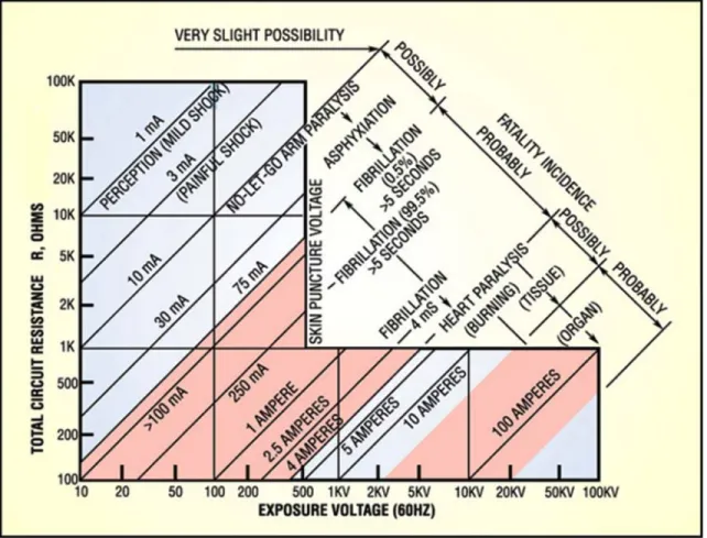
2.2.5 The heart and brain are the parts of the body most vulnerable to electric shock. Some research shows that fatal ventricular fibrillation (disruption of the heart’s rhythmic pumping action) can be initiated by a current flow of as little as 70 milliamperes (mA). Without immediate emergency resuscitation, electrical shock may cause a fatality from direct paralysis of the respiratory system, disruption of rhythmic pumping action, or immediate heart stoppage. Severe injuries, such as deep internal burns, can occur, even if the current does not pass through vital organs or the central nervous system. Specific values for hazardous voltages and for hazardous current flow through the body are not completely reliable because of physiological differences between people.
Current (60 Hz) Physiological phenomena Feeling or lethality
<1.0 mA None Imperceptible
1.0 mA Perception threshold -
0.5 mA – 2.0 mA - Mild sensation
1.0 mA – 4.0 mA - Painful sensation
6.0 mA – 22 mA Paralysis threshold of arms Cannot release hand grip. If no grip, victim may be thrown clear. (May progress to higher current and be fatal.)
18 mA – 30 mA Respiratory paralysis Stoppage of breathing (frequently fatal).
90 mA Fibrillation threshold, 0.5% (greater than or equal to 3 sec exposure)
Heart action discoordinated (probably fatal).
2
Page 14 of 189 250 mA Fibrillation threshold, 99.5% (greater
than or equal to 3 sec exposure)
Heart action discoordinated (probably fatal). 4 A Heart paralysis threshold (no fibrillation) Heart stops for duration of current passage. For
short shocks, heart may restart on interruption of current (usually not fatal from heart
dysfunction).
> 5 A Tissue burning Not fatal unless vital organs are burned.
Table 2.2.5 – Current Range and Effect on a 150 lbs. Person3
2.2.6 There are five principal electrical waveforms of interest that cause various responses to electrical shock:
a. Alternating current (AC) power frequencies b. Direct current (DC)
c. Sub radio frequencies (sub RF) 1 Hz – 5 kHz d. Radio frequencies (RF) 5 kHz – 100 MHz
e. Impulse shock (such as from a capacitor circuit) 2.2.7 AC Response:
a. The most dangerous are AC power frequencies, typically 60 hertz (Hz). Exposure to current at these frequencies causes ventricular fibrillation at the lowest thresholds and causes severe contraction of the muscles with a possible no-let-go response.
3
Page 15 of 189
Fig 2.2.7 – Combined physiological response to the effects of resistance and voltage4
b. Radiofrequency waveforms (5 kilohertz (kHz) to 100 megahertz (MHz)) have decreasing neurological effects with increasing frequency, but energy deposited results in tissue burning.
2.2.8 DC Response:
a. Exposure to DC electric currents can also cause a muscle response at first contact and when releasing, as well as heart fatigue and failure at high enough current levels.
2.2.9 Body Resistance:
a. The resistance of the body is much less if the skin is punctured by a shock above the skin breakdown threshold (400 to 500 V). This allows higher current flow through the body, resulting in more
damage. The amount and duration of current flow determines the severity of the reflex action, the amount of damage to the heart, and neurological and other tissue.
4
Page 16 of 189 2.2.10 Reflex action:
a. Reflex action occurs when electric current causes a violent contraction of the muscles. Such contraction can result in violent recoil, resulting in falling from heights, recoiling into a nearby hazard, or violent muscle contractions resulting in broken bones, torn ligaments, or dislocated joints. Reflex action is enhanced by high-voltage shock as the energy can be delivered more quickly from higher instantaneous currents.
2.2.11 Let-Go Threshold:
a. The so called no-let-go response occurs when continuous shock current keeps the muscles violently contracting such that the victim is clutching the conductor without any ability to release. This only happens with AC waveforms.
2.2.12 Shock Thresholds:
a. Because of the effects of the waveform on the body’s response, the thresholds for acceptable shock vary, depending on the form of the electricity. Acceptable means that below these thresholds there is no injury, and above these thresholds there could be injury.
b. The thresholds are listed in Table 2.2.12 (and repeated in Table 6.2.3) and are found embedded in the hazard classification charts in Sections 3.3-3.8. The threshold values are based on available research and theoretical data. The hazard class values reflect the consensus agreement of a task group that developed the process, based on the collective knowledge and experience. The values should not be considered absolute, but guidance when applying effective hazard analysis to a particular task.
Source Includes Thresholds Hazard Classes (see section 3)
AC 50-60 Hz nominal ≥ 50 V and ≥ 5 mA 1.2, 1.3, 1.4, 1.5
DC All ≥ 100 V and ≥ 40 mA 2.2c, 2.2d, 2.3, 2.4
Capacitors All ≥ 100 V and ≥ 1 J, or
≥ 400 V and ≥ 0.25 J
3.2b, 3.2c, 3.3b, 3.3c, 3.3d, 3.4b, 3.4c
Batteries Lead-Acid and Lithium Ion
Page 17 of 189
Source Includes Thresholds Hazard Classes (see section 3)
Sub-RF 1 Hz to 3 kHz (excluding 50-60 Hz nominal)
≥ 50 V and ≥ 5 mA 6.2a, 6.2b, 6.2c, 6.3, 6.4
RF 3 kHz to 100 MHz A function of frequency 5.2a, 5.2b
Table 2.2.12 – Thresholds for defining shock hazards c. Table notes:
• It is possible for a worker to be exposed to more than one shock hazard at any given location (e.g. multiple types of sources).
• There may be other electrical hazards below the above shock thresholds (e.g., a thermal burn hazard-see Table 2.3.5).
• Injuries may result from startle reactions due to contact with energized components, even though the source energy is too low to do physical damage, such as high-voltage/low-current circuits (e.g., Classes 2.1d and 3.1d).
• Shock and burn hazards from induced and contact RF currents become negligible above 100 MHz (but radiated hazards still exist).
2.3
Electrical Burn
2.3.1 Burns suffered in electrical accidents are of three basic types – electrical current burns, arc burns, and thermal contact burns. The cause of each type of burn is different, and prevention necessitates different controls.
2.3.2 Electrical Current Burns
a. In electrical current burns, tissue damage (whether skin-level or internal) occurs because the body is unable to dissipate the heat from the current flow.
b. Typically, electrical current burns are slow to heal. Such electrical burns result from shock currents, and thus adhering to the shock current thresholds in Table 2.2.12 should prevent electrical current burns.
2.3.3 Arc Flash Burns
a. Arc flash burns are caused by electric arcs and are similar to heat burns from high-temperature sources. Temperatures generated by electric arcs can melt nearby material, vaporize metal in close
Page 18 of 189
vicinity, and burn flesh and ignite clothing at distances of several meters, depending on the energy deposited into the arc. The arc can be a stable low-voltage arc, such as in an arc welder, or a short-circuit arc at higher voltage, resulting in an arc flash and/or arc blast. Such an expanding arc can ignite clothing and/or cause severe burns at a distance from inches to feet.
b. There are four types of arc flash:
• Arc in open air: this type of arc is mostly infrared radiation as opposed to plasma and
typically occurs on power lines in front of the worker. The gases are expanding in relatively all directions equally at once like a sphere. These gases can ignite clothing and cause skin burns as can the infrared radiation. This is the least invasive arc but the most easily measured. It is used in all ASTM test setups to test arc-rated materials.
• Arc in a box: This type is much more dangerous than an arc in open air. With an arc in a box, all of the energy is concentrated in a focused path—usually straight out the doors where you will be standing. This is typical of nearly all arc flash events in industrial electrical equipment (MCC’s, panelboards, switchgear, meter sockets, etc.)
• Arc plasma convective flow: a sustained arc flash event can be driven by the magnetic forces on the plasma cloud, forcing it to travel to the busbar tips, in a direction away from the power source. At the tips it forcefully ejects plasma in a convective flow. This flow can be highly directional, and can also be redirected by bouncing off metal surfaces. The resulting convective flow can lead to very high thermal concentration of the incident energy at a farther distance as opposed to the uniform spread calculated in the arc in open air and the arc in a box scenarios. While the result can exceed the rating of arc flash PPE, it can also be countered by proper body positioning.
• High voltage skin surface tracking arc: a high voltage shock event can sometimes lead to a tracking arc, where the current flows along the surface or just above the skin instead of through the body. In this case there is no metal plasma effect, just the thermal infrared burn from the arc itself. However, this type of arc can propagate underneath the arc flash PPE and ignite flammable undergarments, leading to very serious whole body burns.
c. The arc flash boundary is defined to characterize the distance at which this injury mechanism is severe. Hazard classes that include arc flash hazards are shown in Table 2.3.3. The current values are the short circuit available currents, or fault currents. The threshold values are based on available research and theoretical data. The hazard class values reflect the consensus agreement of the task group that developed the process based on the collective knowledge and experience. The values should not be considered absolute, but, rather as guidance when applying effective hazard analysis to a particular task.
Page 19 of 189
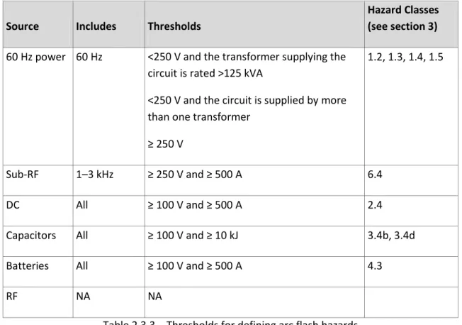
Source Includes Thresholds
Hazard Classes (see section 3)
60 Hz power 60 Hz <250 V and the transformer supplying the circuit is rated >125 kVA
<250 V and the circuit is supplied by more than one transformer
≥ 250 V
1.2, 1.3, 1.4, 1.5
Sub-RF 1–3 kHz ≥ 250 V and ≥ 500 A 6.4
DC All ≥ 100 V and ≥ 500 A 2.4
Capacitors All ≥ 100 V and ≥ 10 kJ 3.4b, 3.4d
Batteries All ≥ 100 V and ≥ 500 A 4.3
RF NA NA
Table 2.3.3 – Thresholds for defining arc flash hazards 2.3.4 Arc Blast Hazards
d. A rapid delivery of electrical energy into an arc can cause additional hazards not covered by arc flash hazards. The acoustical shock wave, or arc blast pressure wave, can burst eardrums at lower levels and can cause cardiac arrest at high enough levels.
e. In addition, high currents (> 100 kA) can cause strong magnetic forces on current-carrying
conductors, which can lead to equipment destruction, or the whipping of conductors. Such arc blast hazards are of particular concern in high-energy facility power circuits (Classes 1.3d, 1.4, and 1.5) and large capacitor banks (Class 3.4d).
2.3.5 Thermal Contact Burns
a. Thermal contact burns are those that occur when skin comes into contact with the hot surfaces of overheated electrical conductors, including conductive tools and jewelry. This injury results from close proximity to a high-current source with a conductive object.
b. Thermal burns can occur from low-voltage/high-current systems that do not present shock or arc flash hazards, and controls should be considered. The controls to prevent injury from shock and arc flash should also protect against thermal contact burn.
Page 20 of 189
c. High-current hazard classes with thermal burn hazards are shown in Table 2.3.5. The threshold values are based on available research and theoretical data. The values are calculated to raise the temperature of the skin to a level that would cause a second-degree burn using the Stoll Curve at a time of two seconds. The hazard class values reflect the consensus agreement of the task group that developed the process based on the collective knowledge and experience. The values should not be considered absolute, but guidance when applying effective hazard analysis to a particular task.
Source Includes Thresholds Hazard Classes (see section 3)
Sub-RF 1–3 kHz <50 V and >1000 W 6.2a
DC All >100 V and >1000 W 2.2a, 2.2b
Capacitors All <100 V and >100 J 3.2a, 3.3a, 3.4a Batteries All <100 V and >1000 W 4.2, 4.3
RF NA NA NA
Table 2.3.5 – Thermal contact burn hazards, not included in shock and arc flash hazards
2.4
Delayed Effects
2.4.1 Damage to the internal tissues may not be apparent immediately after contact with electrical current. Delayed swelling and irritation of internal tissues are possible. In addition, imperceptible heart
arrhythmia can progress to ventricular fibrillation.
2.4.2 In some cases, workers have died two to four hours after what appeared to be a mild electrical shock. Immediate medical attention may prevent death or minimize permanent injury. All electrical shocks should be reported immediately.
2.5
Battery Hazards
2.5.1 During maintenance or other work on batteries and battery banks, there are electrical and physical hazards that should be considered. In addition, when working near or on flooded lead-acid storage batteries additional chemical and explosion hazards should be considered.
2.5.2 The hazards associated with various types of batteries and battery banks include: a. Electric shock;
Page 21 of 189
c. Chemical burns from electrolyte spills or from battery surface contamination; d. Fire or explosion due to hydrogen;
e. Physical injury from lifting or handling the cells; or f. Fire from overheated electrical components.
2.6
Other Hazards
2.6.1 Low-Voltage Circuits
a. Low-voltage circuits, which are not hazardous themselves, are frequently used adjacent to hazardous circuits. A minor shock can cause a worker to rebound into the hazardous circuit. b. Such an involuntary reaction may also result in bruises, bone fractures, and even death from
collisions or falls. The hazard is due to the secondary effects of the reflex action. 2.6.2 Operating Electrical Disconnects
a. An arc may form when a short circuit occurs between two conductors of differing potential, or when two conductors carrying current are separated, such as a safety switch attempting to interrupt the current. If the current involved is high enough, the arc can cause injury, ignite flammable materials or initiate an explosion in combustible or explosive atmospheres.
b. Injury to personnel can result from the arc flash, or arc blast, resulting in severe burns to exposed skin, or ignition of clothing. Equipment or conductors that overheat, due to overload, may ignite flammable materials. Extremely high-energy arcs can cause an arc blast that sends shrapnel flying in all directions.
2.6.3 R&D Electrical Equipment
a. Analyzing electrical hazards associated with R&D equipment may present challenges beyond that associated with standard electrical distribution equipment. Some R&D equipment is custom designed and built and may need specific qualifications for workers that operate or maintain the equipment. An uncommon or unique design can be difficult to analyze for hazard identification. b. Regardless, the hazard analysis should include shock, potential arc or thermal sources. Acoustic
shock wave, pressure shock wave and shrapnel are potential hazards that should be considered as well. Once the hazards have been identified, a risk mitigation plan should be developed.
c. Personnel working on electrical equipment should be specifically qualified through training specific to the work to be done. The scope of such additional training depends on the hazards associated with the equipment.
Page 22 of 189
3
Electrical Hazard Classification
3.1
Explanation of the electrical hazard classification structure
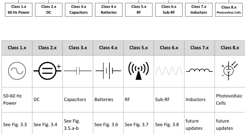
3.1.1 The electrical hazard classification charts cover eight broad categories: 50-60 Hz, DC, capacitors, batteries, Sub-RF, RF, inductors, and photovoltaic. Table 3.2 shows these eight major categories with a pointer to the figure where each category is broken into the individual classes. These classes, taken collectively, represent the electrical hazards found in electrical equipment.
3.1.2 All classes should be considered when identifying the hazards associated with any piece of electrical equipment. A single piece of equipment may have multiple electrical hazard classifications, and the combination of hazards must be addressed by appropriate safety-related work practices.
3.1.3 To aid hazard identification, each chart has cross-reference notes in the upper right hand corner. For example, the DC chart has cross-reference notes to capacitance, inductance, Sub-RF, battery, and 50-60 Hz hazard charts. Workers shallhave a thorough understanding of the equipment they are analyzing for hazards. Consulting manuals and schematics and speaking with factory service representatives and electrical SMEs are ways to ensure that all of the hazards are fully understood and that all the pertinent classes are taken into account.
3.1.4 Some guidelines on use of the hazard classification charts are provided, below. They are general, and there may be exceptions to each one:
a. If these guidelines and the equipment are not understood, an SME should be consulted. b. All equipment gets its power from 50-60 Hz (Classes 1.x) or batteries (Classes 4.x). Thus, all
equipment starts with one of those classes.
c. Most small appliances, hand tools, and portable laboratory equipment plugs into Class 1.2. In general, if it can be carried, it most likely it uses 120 to 240 V.
d. Larger facility and laboratory equipment may use up to 480 V (Class 1.3). Often, if it is a large motor, or consumes significant power, it may be Class 1.3.
e. DC power supplies need to be evaluated for both DC (Class 2.x) and Capacitance (Class 3.x). f. All UPSs have hazards in Classes 4.x as well as 1.x, since they usually are tied into facility power
Page 23 of 189
3.1.5 The colors used in each hazard Class box are organized in increasing hazard: blue, green, yellow, red, and maroon. Some general statements can be made about each color. There may be exceptions.
Light blue and white boxes are not hazard classes, but are decision points.
A blue Class (X.0) indicates no hazard, and no engineering or administrative controls are needed.
A green Class (X.1) indicates little to no hazards, few, or no, engineering or administrative controls are needed.
A yellow Class (X.2) indicates injury or death could occur by close proximity or contact; often the hazard is shock or contact burn. Engineering controls are necessary for operation (e.g., listing or equipment approval), and administrative controls are necessary for electrical work in this Class.
A red Class (X.3) indicates injury or death could occur by proximity or contact; often the hazard is shock, contact burn, or arc-flash burn; engineering controls are necessary for operation (e.g., listing or equipment approval), and administrative controls are necessary for electrical work in this Class.
Maroon Class (X.4 and X.5) is the highest level of risk; significant engineering and administrative controls are necessary to manage the hazard in these classes.
Gray, Class 3.1c, takes the user outside of electrical safety controls, as the primary hazard is chemical explosion.
3.1.6 Modes of work (for a description of Modes of work, see 6.4-6.7): a. Mode 0 – Electrically Safe Work Condition
b. Mode 1 – Establishing an Electrically Safe Work Condition c. Mode 2 – Energized Diagnostics (Testing & Troubleshooting) d. Mode 3 – Energized Repair Work (EEWP)
Page 24 of 189
3.2
Classification Matrix
Class 1.x Class 2.x Class 3.x Class 4.x Class 5.x Class 6.x Class 7.x Class 8.x
50-60 Hz
Power DC Capacitors Batteries RF Sub-RF Inductors
Photovoltaic Cells
See Fig. 3.3 See Fig. 3.4 See Fig.
3.5.a-b See Fig. 3.6 See Fig. 3.7 See Fig. 3.8
future updates
future updates
Table 3.2 – Complete Electrical Hazard Classification System Showing Eight Major Classes
Class 1.x 60 Hz Power Class 2.x DC Class 3.x Capacitors Class 4.x Batteries Class 5.x RF Class 6.x Sub-RF Class 7.x
Inductors Photovoltaic Cells Class 8.x
Choose the source(s) of energy
Page 25 of 189
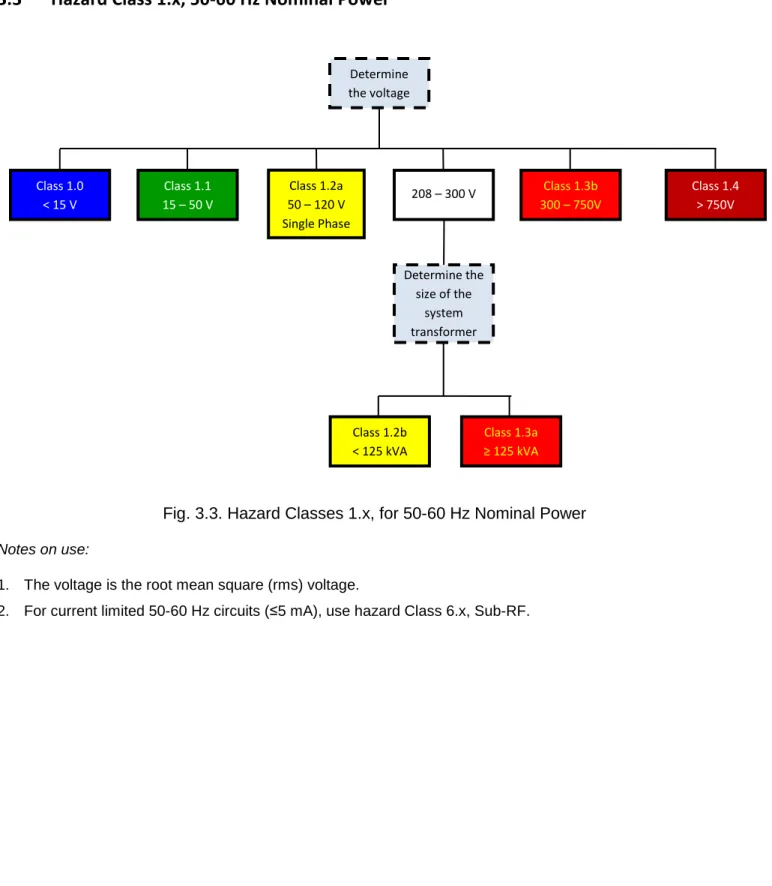
3.3
Hazard Class 1.x, 50-60 Hz Nominal Power
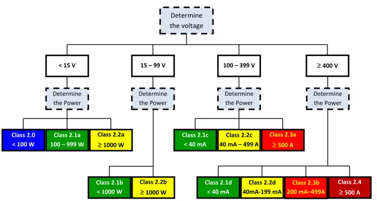
Fig. 3.3. Hazard Classes 1.x, for 50-60 Hz Nominal Power
Notes on use:
1. The voltage is the root mean square (rms) voltage.
2. For current limited 50-60 Hz circuits (≤5 mA), use hazard Class 6.x, Sub-RF.
Determine the voltage Class 1.0 < 15 V Class 1.1 15 – 50 V 208 – 300 V Class 1.3b 300 – 750V Determine the size of the system transformer Class 1.3a ≥ 125 kVA Class 1.2b < 125 kVA Class 1.4 > 750V Class 1.2a 50 – 120 V Single Phase
Page 26 of 189
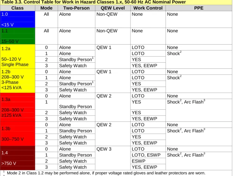
Table 3.3. Control Table for Work in Hazard Classes 1.x, 50-60 Hz AC Nominal Power
Class Mode Two-Person QEW Level Work Control PPE
1.0 <15 V
All Alone Non-QEW None None
1.1
15–50 V
All Alone Non-QEW None None
1.2a
50–120 V Single Phase
0 Alone QEW 1 LOTO None
1 Alone LOTO Shock2
2 Standby Person1 YES
3 Safety Watch YES, EEWP
1.2b 208–300 V 3-Phase <125 kVA
0 Alone QEW 1 LOTO None
1 Alone LOTO Shock2
2 Standby Person1 YES
3 Safety Watch YES, EEWP
1.3a
208–300 V
≥125 kVA
0 Alone QEW 2 LOTO None
1
Standby Person
YES Shock2, Arc Flash3
2 Safety Watch YES
3 Safety Watch YES, EEWP
1.3b
300–750 V
0 Alone QEW 2 LOTO None
1 Standby Person LOTO Shock2, Arc Flash3
2 Safety Watch YES
3 Safety Watch YES, EEWP
1.4 >750 V
0 Alone QEW 3 LOTO None
1 Standby Person LOTO, ESWP Shock2, Arc Flash3
2 Safety Watch ESWP
3 Safety Watch YES, EEWP
1
Mode 2 in Class 1.2 may be performed alone, if proper voltage rated gloves and leather protectors are worn. 2
Determine PPE by performing a shock hazard analysis using methods covered in Section 7.1. 3
Page 27 of 189
3.4
Hazard Class 2.x, DC
Fig. 3.4 Hazard Classes 2.x, DC
Notes on use:
1. The voltage is the DC voltage.
2. Power is available short-circuit power. 3. Current is available short-circuit current.
4. Most equipment supplying DC also needs to be evaluated for capacitance hazards in Class 3.x. Determine the voltage < 15 V Determine the Power 15 – 99 V Determine the Power 100 – 399 V Determine the Power ≥ 400 V Determine the Power Class 2.0 < 100 W Class 2.1a 100 – 999 W Class 2.2a ≥ 1000 W Class 2.1b < 1000 W Class 2.2b ≥ 1000 W Class 2.1c < 40 mA Class 2.2c 40 mA – 499 A Class 2.3a ≥ 500 A Class 2.2d 40mA-199 mA Class 2.3b 200 mA–499A Class 2.4 ≥ 500 A Class 2.1d < 40 mA
Page 28 of 189
Table 3.4. Control Table for Work in Hazard Classes 2.x, DC
Class Mode Two-Person QEW Level Work Control PPE
2.0
≤15 V, ≤100 W
All Alone Non-QEW None None
2.1a,b,c,d
≤100 V, ≤1 kW or >100 V, ≤40 mA
All Alone Non-QEW None None
2.2a
≤15 V >1 kW
All Alone Non-QEW None None
2.2b 15–100 V >1 kW
All Alone Non-QEW LOTO None
Alone LOTO Insulated tools, gloves
Alone NO Insulated tools, gloves
Alone NO Insulated tools, gloves
2.2c 100–400 V 40 mA–500 A
0 Alone QEW 1 LOTO None
1 Alone LOTO Shock1
2 Standby Person YES
33 Safety Watch YES, EEWP
2.2d >400 V 40–200 mA
0 Alone QEW 1 LOTO None
1 Alone LOTO Shock1
2 Standby Person YES
33 Safety Watch YES, EEWP
2.3a 100–400 V >500 A
0 Alone QEW 1 LOTO None
1 Standby Person LOTO Shock1, Arc Flash2
23 Safety Watch YES
34 Safety Watch YES, EEWP
2.3b >400 V 200 mA–500 A
0 Alone QEW 2 LOTO None
1 Standby Person LOTO Shock1, Arc Flash2
23 Safety Watch YES
34 Safety Watch YES, EEWP
2.4 >400 V >500 A
0 Alone QEW 2 LOTO None
1 Standby Person LOTO Shock1, Arc Flash2
24 Safety Watch YES
34 Safety Watch YES, EEWP
1
Determine PPE by performing a shock hazard analysis using methods covered in Section 7.1.
2
Determine PPE by performing an arc flash hazard analysis using methods covered in Section 8.1. e. 3 DO NOT move probes while energized.
Page 29 of 189
3.5
Hazard Class 3.x, Capacitors
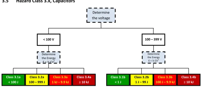
Fig. 3.5a – Hazard Classes 3.x, Capacitors, <400 V
Notes on use:
1. Voltage is peak of the AC, peak impulse or DC maximum charge voltage on the capacitor. 2. Energy is maximum energy stored in the capacitor as determined by E = ½ CV2.
3. The hazards for less than 100 V, Classes 3.2a, 3.3a, 3.4a, are high current through a short circuit, such as tools and jewelry.
4. The hazards for 100 – 399 V, Classes 3.2b, 3.3b, 3.4b, are high current through a short circuit, and a shock hazard.
5. Class 3.4b has an added hazard of mechanical damage due to high currents and strong pulsed magnetic forces during a short circuit.
Determine the voltage < 100 V Determine the Energy E = ½ CV2 Class 3.1a < 100 J Class 3.2a 100 – 999 J Class 3.3a 1 kJ – 9.9 kJ Class 3.2b 1 J – 99 J Class 3.3b 100 J – 9.9 kJ Class 3.4b ≥ 10 kJ Class 3.1b < 1 J Class 3.4a ≥ 10 kJ 100 – 399 V Determine the Energy E = ½ CV2
Page 30 of 189
Table 3.5a. Control Table for Work in Hazard Classes 3.x, Capacitors (< 400 V)
Class Mode Two-Person QEW Level Work Control PPE Stored Energy Removal
3.1a < 100 V < 100 J
All Alone Non-QEW None None
3.1b 100 – 399 V < 1 J
All Alone Non-QEW None None
3.2a < 100 V 100 J – 999 J 0 Alone QEW 1 + Capacitor Safety LOTO None
1 Alone LOTO Eye, No Jewelry Soft Ground Hook
2 Standby Person YES Eye, No Jewelry
3 Safety Watch YES Eye, No Jewelry
3.2b 100 – 399 V 1 –99 J 0 Alone QEW 1 + Capacitor Safety LOTO None
1 Alone LOTO Insulated tools, gloves Soft Ground Hook > 5 J
2 Standby Person YES Insulated tools, gloves
3 Standby Person YES, EEWP Insulated tools, gloves 3.3a < 100 V 1 kJ –9.9 kJ 0 Alone QEW 2 + Capacitor Safety LOTO None
1 Standby Person LOTO Eye, No Jewelry Soft Ground Hook > 5 J
2 Safety Watch YES Eye, No Jewelry
3 Safety Watch YES, EEWP Eye, No Jewelry
3.3b 100 – 399 V 100 J –9.9 kJ 0 Alone QEW 2 + Capacitor Safety LOTO None
1 Standby Person LOTO Eye, Insulated tools,
gloves
Soft Ground Hook
2 Safety Watch YES Eye, Insulated tools,
gloves
34 Safety Watch YES, EEWP Eye, Insulated tools, gloves 3.4a <100 V ≥10 kJ 0 Alone QEW 2 + Capacitor Safety LOTO None
1 Standby Person LOTO Eye, No Jewelry Remote grounding
23 Safety Watch YES Eye, No Jewelry Remote testing
34 Safety Watch YES, EEWP Eye, No Jewelry
3.4b 100 – 399 V ≥10 kJ 0 Alone QEW 2 + Capacitor Safety LOTO None
1 Standby Person LOTO Eye, Ear, shock1, arc flash2
Remote grounding
23 Safety Watch YES Eye, Ear, shock1, arc
flash2
Remote testing 34 Safety Watch YES, EEWP Eye, Ear, shock1, arc
flash2
1
Determine PPE by performing a shock hazard analysis using methods covered in Section 7.1.
2
Determine PPE by performing an arc flash hazard analysis using methods covered in Section 8.1.
3 This mode of work should be avoided or done remotely. 4
This mode of work should be avoided.
Notes on use:
1. PPE–eye is proper eye protection, either goggles or a face shield, for higher energies.
2. PPE–no jewelry for low voltage capacitors, means no jewelry on the hands (e.g., rings, watches) and no dangling jewelry or other objects (e.g., badge).
3. Column ‘Stored Energy Removal’ is the method used to discharge lower-energy capacitors, or apply a safety ground on higher-energy capacitors.
4. “Remote grounding” means using engineering methods to discharge and verify the capacitors without worker exposure (e.g., a capacitor remote “dump” or discharge system).
5. “Remote testing” means using sensors and instruments that are placed during a Mode 0 condition, then observed from a safe location during Mode 2 work.
Page 31 of 189
Fig. 3.5b. Hazard Classes 3.x, Capacitors, >400 V
Notes on use:
1. Voltage is peak of the AC, peak impulse or DC maximum charge voltage on the capacitor. 2. Energy is maximum energy stored in the capacitor as determined by E = ½ CV2.
3. The hazards for greater than 400 V, Classes 3.2c, 3.3c, 3.3d, 3.4c are high current through a short circuit, and a shock hazard with a strong reflex action for Class 3.2c, and serious tissue injury and/or death for 3.3c and above.
4. Class 3.3d and 3.4c have the added hazards of mechanical damage due to high currents and strong pulse magnetic forces during a short circuit.
5. For Class 3.1c, the hazard is not electrical; refer to an explosive or hazardous location SME to manage the hazard. ESD Determine the Location Class 3.0 Non-Hazardous Location Class 3.1c Hazardous Location Class 3.3c 50 J – 999 J Class 3.3d 1 kJ – 9.9 kJ Class 3.4c ≥ 10 kJ Class 3.2c 0.25 J – 49 J Class 3.1d < 0.25 J Capacitor Determine the Energy E = ½ CV2 the voltage ≥ 400 V Determine the Source
Page 32 of 189
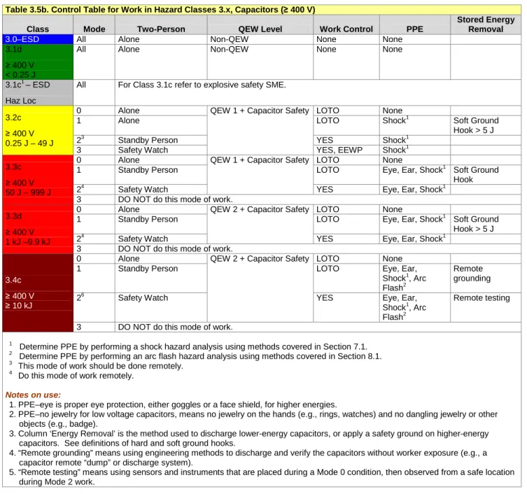
Table 3.5b. Control Table for Work in Hazard Classes 3.x, Capacitors (≥ 400 V)
Class Mode Two-Person QEW Level Work Control PPE
Stored Energy Removal
3.0–ESD All Alone Non-QEW None None
3.1d
≥ 400 V < 0.25 J
All Alone Non-QEW None None
3.1c1 – ESD
Haz Loc
All For Class 3.1c refer to explosive safety SME. 3.2c
≥ 400 V 0.25 J – 49 J
0 Alone QEW 1 + Capacitor Safety LOTO None
1 Alone LOTO Shock1 Soft Ground
Hook > 5 J
23 Standby Person YES Shock1
3 Safety Watch YES, EEWP Shock1
3.3c
≥ 400 V 50 J – 999 J
0 Alone QEW 1 + Capacitor Safety LOTO None
1 Standby Person LOTO Eye, Ear, Shock1 Soft Ground
Hook
24 Safety Watch YES Eye, Ear, Shock1
3 DO NOT do this mode of work. 3.3d
≥ 400 V 1 kJ –9.9 kJ
0 Alone QEW 2 + Capacitor Safety LOTO None
1 Standby Person LOTO Eye, Ear, Shock1 Soft Ground
Hook > 5 J
24 Safety Watch YES Eye, Ear, Shock1
3 DO NOT do this mode of work.
3.4c
≥ 400 V
≥ 10 kJ
0 Alone QEW 2 + Capacitor Safety LOTO None
1 Standby Person LOTO Eye, Ear,
Shock1, Arc Flash2
Remote grounding
26 Safety Watch YES Eye, Ear,
Shock1, Arc Flash2
Remote testing 3 DO NOT do this mode of work.
1
Determine PPE by performing a shock hazard analysis using methods covered in Section 7.1.
2 Determine PPE by performing an arc flash hazard analysis using methods covered in Section 8.1. 3
This mode of work should be done remotely.
4
Do this mode of work remotely.
Notes on use:
1. PPE–eye is proper eye protection, either goggles or a face shield, for higher energies.
2. PPE–no jewelry for low voltage capacitors, means no jewelry on the hands (e.g., rings, watches) and no dangling jewelry or other objects (e.g., badge).
3. Column ‘Energy Removal’ is the method used to discharge lower-energy capacitors, or apply a safety ground on higher-energy capacitors. See definitions of hard and soft ground hooks.
4. “Remote grounding” means using engineering methods to discharge and verify the capacitors without worker exposure (e.g., a capacitor remote “dump” or discharge system).
5. “Remote testing” means using sensors and instruments that are placed during a Mode 0 condition, then observed from a safe location during Mode 2 work.
Page 33 of 189
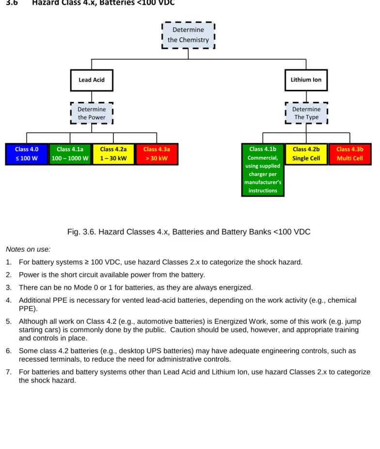
3.6
Hazard Class 4.x, Batteries <100 VDC
Fig. 3.6. Hazard Classes 4.x, Batteries and Battery Banks <100 VDC
Notes on use:
1. For battery systems ≥ 100 VDC, use hazard Classes 2.x to categorize the shock hazard. 2. Power is the short circuit available power from the battery.
3. There can be no Mode 0 or 1 for batteries, as they are always energized.
4. Additional PPE is necessary for vented lead-acid batteries, depending on the work activity (e.g., chemical PPE).
5. Although all work on Class 4.2 (e.g., automotive batteries) is Energized Work, some of this work (e.g. jump starting cars) is commonly done by the public. Caution should be used, however, and appropriate training and controls in place.
6. Some class 4.2 batteries (e.g., desktop UPS batteries) may have adequate engineering controls, such as recessed terminals, to reduce the need for administrative controls.
7. For batteries and battery systems other than Lead Acid and Lithium Ion, use hazard Classes 2.x to categorize the shock hazard.
Determine the Chemistry Lead Acid Determine the Power Class 4.1b Commercial, using supplied charger per manufacturer’s instructions Class 4.2b Single Cell Class 4.3b Multi Cell Class 4.0 ≤ 100 W Class 4.1a 100 – 1000 W Class 4.2a 1 – 30 kW Class 4.3a > 30 kW Lithium Ion Determine The Type
Page 34 of 189
Table 3.6a. Control Table for Work in Hazard Classes 4.xa, Batteries (Lead Acid) <100 VDC
Class Mode Two-Person QEW Level Work Control PPE
4.0 <100 W
All Alone Non-QEW None None
4.1a
100–1000 W
All Alone Non-QEW None No Jewelry
4.2a
1–30 kW
2 Alone Non-QEW YES Eye, No Jewelry
3 Alone Non-QEW YES Eye, No Jewelry
4.3a
>30 kW
2 Alone Non-QEW YES Eye, No Jewelry
3 Alone Non-QEW YES Eye, No Jewelry,
Special Battery Tools Notes on use:
1 For greater than 100 VDC, use hazard Classes 2.x to categorize the shock hazard.
2 For battery banks greater than 100 VDC, break up bank for energized work, when possible.
Table 3.6b. Control Table for Work in Hazard Classes 4.xb, Batteries (Lithium Ion) <100 VDC
Class Mode
Two-Person QEW Level Work Control Additional Controls
4.1b
Commercial
While Charging
Alone Non-QEW Charge per
manufacturer’s instructions using the supplied charger. None 4.2b1 Single Cell While Charging
Alone Non-QEW YES None
4.3b1
Multi Cell
While Charging
Alone Non-QEW YES Containment, monitor
temp using thermocouples 1
Ensure, through AHJ equipment approval that the batteries and battery packs have integral protection and that the charging circuit is matched to the battery or battery pack.
Notes on use:
1. For greater than 100 VDC, use hazard Classes 2.x to categorize the shock hazard.
Page 35 of 189
3.7
Hazard Class 5.x, RF Circuits (5 kHz to 100 MHz)
Fig. 3.7. Hazard Classes 5.x, RF Circuits 5 kHz to 100 MHz (f is in MHz)
1. “f” in the Chart is frequency in MHz. “1000f mA” means 1000 times the frequency in MHz. For example, if the frequency is 18 kHz, the shock current threshold is 0.018x1000 = 18 mA.
2. Classes 5.x only address the RF shock hazard. They do NOT address the exposure to electromagnetic
fields.
3. The RF hazard classification chart in Fig. 3.7 determines if the RF source can put out sufficient current to be a shock/burn hazard. However, it does not take into account the body impedance, which is necessary to determine if the source can drive these currents into the body. The tools for body impedance modeling are too detailed to put into this document.
4. Types of waveforms and other factors that are not included in this table will need to be evaluated by competent persons for all hazards.
Determine the Frequency 5 kHz – 99 kHz Determine the Current Class 5.1b < 100 mA Class 5.2b ≥ 100 mA Class 5.1a < 1000f mA Class 5.2a ≥ 1000f mA 0.1 – 100 MHz Determine the Current
Page 36 of 189
Table 3.7. Control Table for Work in Classes 5.x, RF Circuits (5 kHz to 100 MHz)
Class Mode Two-Person QEW Level
Work
Control PPE
5.1a
0.003–0.1 MHz <1000f mA
All Alone Non-QEW None None
5.1b
0.1–100 MHz <100 mA
All Alone Non-QEW None None
5.2a
0.003–0.1 MHz
≥1000f mA
All Alone QEW 1
Must perform RF hazard
analysis bas 5.2b 0.1–100 MHz ≥100 mA
Page 37 of 189
3.8
Hazard Class 6.x, Sub-RF Circuits (1 Hz to 5 kHz)
Fig. 3.8. Hazard Classes 6.x, Sub-RF Circuits (1 Hz to 5 kHz)
Notes on use:
1. This hazard class is not to be used for 50-60 Hz power, except for power limited 50-60 Hz circuits that cannot have currents over 5 mA.
2. Power is available short-circuit power. 3. Current is available short-circuit current.
Determine the Voltage ≤ 50 V Determine the Power > 250 V Determine the Current Class 6.1a ≤ 1000 W Class 6.2a > 1000 W Class 6.1c ≤ 5 mA Class 6.4 > 500 A Class 6.3 75 mA – 500 mA Class 6.2c 5 – 75 mA Class 6.1b ≤ 5 mA Class 6.2b > 5 mA 50 – 250 V Determine the Current
Page 38 of 189
Table 3.8. Control Table for Work in Classes 6.x, Sub-RF Circuits (1 Hz to 5 kHz)
Class Mode Two-Person QEW Level Work Control PPE
6.1a,b,c
≤50 V, ≤1 kW or
>50 V, ≤5 mA
All Alone Non-QEW None None
6.2a
≤50 V >1 kW
0 Alone Non-QEW LOTO None
1 Alone LOTO Shock1
2 Standby Person YES Shock1
34 Safety Watch YES, EEWP Shock1
6.2b 50–250 V >5 mA
0 Alone QEW 1 LOTO None
1 Alone LOTO Shock1
2 Standby Person YES Shock1
34 Safety Watch YES, EEWP Shock1
6.2c >250 V 5–75 mA
0 Alone QEW 1 LOTO None
1 Alone LOTO Shock1
2 Standby Person YES Shock1
34 Safety Watch YES, EEWP Shock1
6.3 >250 V 75 mA–500 A
0 Alone QEW 2 LOTO None
1 Standby Person LOTO Shock1
23 Safety Watch YES Shock1
34 Safety Watch YES, EEWP Shock1
6.4 >250 V >500 A
0 Alone QEW 2 LOTO None
1 Standby Person LOTO Shock1, Arc Flash2
24 Safety Watch YES Shock1, Arc Flash2
34 Safety Watch YES, EEWP Shock1, Arc Flash2
1
Perform a shock hazard analysis using methods covered in Section 7.1. 2
Perform an arc flash hazard analysis using methods covered in Section 8.1. 3
DO NOT move probes while energized. 4
Page 39 of 189
Page 40 of 189
4
Electrical Safety Principles & Controls
4.1
Principles of Electrical Safety
4.1.1 Electricity is different from other forms of hazardous energy, because it is both undetectable by human senses and potentially immediately fatal upon contact. Since we use electricity every day and
everywhere in our lives, this requires a broad application of specialized equipment construction methods and safe work practices to prevent serious injuries or death.
4.1.2 All electrical equipment must be installed and used in accordance with manufacturer’s instructions. Equipment shall be approved for use (accepted by the Electrical AHJ) and shall not be modified or used outside of its approval intent. See the Electrical Equipment Safety Program for more information. 4.1.3 Sufficient training is required to safely interact with electrical equipment. Operators must be trained to
operate equipment within its design intent and to not defeat engineering controls.
4.1.4 Personnel who service, modify, repair or build electrical equipment must be able to recognize the hazards and establish controls to prevent injury. These personnel are called Qualified Electrical Workers (QEW’s).
4.1.5 The most fundamental aspect of QEW training is the ability to Test Before Touch. Without an innate human sense to detect a hazardous condition, QEW’s must understand how to properly use test equipment to prove an Electrically Safe Work Condition.
4.1.6 Live repair work is considered extremely hazardous and is generally prohibited. Exceptions can be made but require detailed justification and approval by senior management (EEWP – Section 6.6). 4.1.7 Whenever possible, all work performed on equipment will be performed deenergized. In order to
prove and maintain deenergization, QEW’s must follow a strict process to establish an Electrically Safe Work Condition. This process involves both Lockout/Tagout and Test Before Touch. Because this is so fundamental to safe electrical work, it is captured in the electrical safety medallion in Fig. 4.1.7.
Page 41 of 189
Fig. 4.1.7 – Electrical Safety Medallion
4.1.8 Some forms of diagnostics require the equipment to be energized while circuit parts are exposed. Only QEW’s with the proper PPE may perform diagnostics.
4.1.9 Some combinations of switching, testing and LOTO can involve significant procedural complexity. In these cases, written work plans are developed, reviewed and approved by knowledgeable parties in advance and executed with formal procedural compliance. Refer to 6.8 for how and when to build an Electrical Safe Work Procedure.
4.1.10 Proper body positioning must be an integral part of both everyday work habits and detailed work planning. This principle is embedded in the shock protection and arc flash protection boundaries, but must also be emphasized in everything from routine switching activities to setting up barriers and barricades.
4.2
Application of ISM to Electrical Safety
4.2.1 The Integrated Safety Management process applies in full to electrical work.
4.2.2 The general process for implementing ISM can be found in
4.2.3 Every electrical job requires an appropriate level of electrical hazard analysis, work planning, authorization and direct field supervision that is commensurate with the risk level of the job.
Page 42 of 189 4.2.4 ISM Steps for Electrical Work:
a. Step 1: Define the scope of work b. Step 2: Analyze the hazards
c. Step 3: Develop/implement controls d. Step 4: Perform work
e. Step 5: Feedback and improve
4.3
Planning Electrical Work
4.3.1 Every electrical job shall be planned in advance of performing the job briefing.
4.3.2 Planning can be formal or informal, depending on the level of risk and the determination of the risk assessment.
4.3.3 Planning is simply performing the first three steps in the ISM process loop in 4.2.4: a. Define the scope of work
b. Analyze the Hazards
Page 43 of 189
4.3.4 Certain higher risk jobs require the plan to be formally documented in an Electrical Safe Work Procedure (ESWP). See 6.8.
4.3.5 Electrical Hazard Analysis
a. If the energized electrical conductors or circuit parts operating above the shock hazard thresholds of 2.2.12 are not placed in an Electrically Safe Work Condition, other safety-related work practices, such as the ones described in Sections 6 through 10, shall be used to protect employees who might be exposed to the electrical hazards involved.
b. Such work practices shall protect each employee from arc flash and from contact with energized electrical conductors or circuit parts, operating above the shock hazard thresholds of 2.2.12, directly with any part of the body or indirectly through some other conductive object.
c. Work practices that are used shall be suitable for the conditions under which the work is to be performed and for the voltage level of the energized electrical conductors or circuit parts.
d. Appropriate safety-related work practices shall be determined before any person is exposed to the electrical hazards involved by using both shock hazard analysis and arc flash hazard analysis.
• A shock hazard analysis shall be performed in accordance with 7.1. • An arc flash hazard analysis shall be performed in accordance with 8.1.
e. The electrical hazard analysis determines the type and rating of shock and arc flash PPE, as well as approach boundaries to be used.
4.3.6 Developing Controls
a. Depending on the results of the Electrical Hazard Analysis, controls must be selected to minimize both the risk to the persons performing the work and to persons who may be in the area. Controls are selected from Section 6. The following are examples of questions to consider when planning the work.
b. Determine who can perform the work. • Who will be the Person In Charge? • What level of QEW is required?
• Is a Standby Person or Safety Watch required?
c. Determine what level of documentation or authorization is required. • Is a written ESWP required?
• Is an EETP or EEWP required?
Page 44 of 189 d. Determine how to minimize exposure to the workers.
• Can the arc flash energy be reduced? • Can parts of the system be locked out?
• Can additional temporary barriers be placed over exposed parts or openings? e. Determine how to control access to the work area.
• Are barricades required?
• Should attendants be stationed to control access? f. Determine what other additional controls should apply.
4.4
Hierarchy of controls
4.4.1 To prevent and mitigate hazards, controls must be tailored to the work being performed, the risk of harm posed by the work, and the extent or degree of harm that could occur while performing the work. This tailoring of controls to hazards based upon risk is generally referred to as the “graded approach.” 4.4.2 The preferred hierarchy of controls is:
a. Elimination or substitution of the hazards: in the design of equipment or apparatus, careful consideration should be made when applying hazardous electrical power to a device. For example, control and interlock circuitry could be designed to operate at 24 VDC instead of 120 VAC.
b. Engineering controls: in the design of equipment or apparatus, permanent guarding, enclosing, or insulation of hazardous voltage sources to prevent unnecessary exposure to the operator.
c. Administrative controls: implementation of an Electrically Safe Work Condition (Lockout/Tagout), restricted access to qualified electrical workers, and documented safe work plans are examples of administrative controls.
d. Personal protective equipment: working on energized equipment while protected with PPE is a last resort.
4.4.3 The tailoring process should include: a. Identifying controls for specific hazards b. Establishing boundaries for safe operation c. Implementing and maintaining controls
Page 45 of 189
4.5
Authorization
4.5.1 Authorization to perform electrical work is covered by the ES&H Manu
program. All electrical work shall require line management authorization.
4.5.2 Specific authorization is to be provided by the supervisor after the employee has been approved as a Qualified Electrical Worker by the Electrical AHJ for Safe Work Practices, has satisfied the EHS course requirement and has received equipment-specific training. The supervisor must ensure that the employee is thoroughly familiar with the equipment (within the context of his or her job function) and with the energy-control procedures.
4.5.3 The authorizing person shall consider the following factors in authorizing electrical work: a. Who is performing the work? Are they suitably qualified and experienced?
b. Who is supervising the work? Are they suitably qualified and experienced? c. Is a written procedure necessary or advised (ESWP)?
d. Are any permits required and have they been approved?
e. What system operational conditions will (or should) be required? Are these accounted for in the plan?
f. What could go wrong and what should be done about it? Is the level of planning and supervision appropriate for the level of risk?
4.6
Executing the Plan
4.6.1 Every electrical job shall have a designated Person In Charge (PIC) (6.9).
4.6.2 The PIC shall perform a Job Briefing with all persons involved prior to executing the job (6.12).
4.6.3 Individual Qualified Electrical Workers should think through the set of self-control questions to ensure they are adequately prepared for the task (4.7).
4.6.4 The PIC should remain alert for changes in the scope of work that may naturally develop during the execution of the plan. Individual QEW’s shall notify the PIC for any change in the scope of work. A change in scope shall trigger a review of the hazards and controls.
Page 46 of 189
4.7
Self-Controls for the Qualified Electrical Worker
4.7.1 Electrical safety self-control is a process by which one performs his or her own safety analysis before beginning any task. This is the first step of a personal hazard/risk analysis. It can be accomplished by simply asking questions of oneself. If one can honestly answer “yes” to all of the following questions, he or she has done well at controlling his or her own safety. If one responds “no” to any of the questions, there is a safety concern that he or she should address before proceeding with the work. 4.7.2 This set of self-control questions makes the employee slow down and think about what he or she is
going to do. Applying these controls can significantly reduce the probability of the employee being injured or killed while performing electrical work.
a. Do I fully understand the scope of the work?
b. Am I trained and qualified to perform this work safely?
c. Have I performed this type of task before; if not, have I discussed the details with my supervisor? d. Have I thought about possible hazards associated with this work and taken steps to protect myself
against them?
e. Have I determined whether or not I will be near exposed energized parts?
f. If I am going to be exposed to energized parts, can they be put into an Electrically Safe Work Condition? [If “No,” skip to item i.]
g. Did I verify, using appropriate protective and test equipment, that the conductors or equipment are in a de-energized state?
h. Have I applied a lockout/tagout device?
i. If I will be exposed to energized parts, do I know what voltage levels are involved? j. Do I know the safe approach distance to protect against the electrical shock hazard? k. Do I know the safe approach distance to protect against the electrical arc/flash hazard? l. If a permit for energized work is required, have I obtained one?
m. Do I have the proper electrical PPE for this type of energized electrical work?
n. Do I have the appropriate voltage-rated tools and test equipment, in the proper working order, to perform this work?
Page 47 of 189
o. Have I considered and controlled the following factors in my work environment? • Close working quarters
• High traffic areas
• Intrusion/distraction by others • Flammable/explosive atmosphere • Wet location
• Illumination in the area
p. Do I understand that doing the work safely is more important than the time pressure to complete the work?
Page 48 of 189
5
General Electrical Safety for All Persons
5.1
Scope
5.1.1 This section applies for all personnel at Berkeley Lab, both QEWs and non-QEWs.
5.1.2 This section deals primarily with workplace electrical safety. This includes working around or with electrical equipment, but does not include working on or inside electrical equipment.
5.2
General requirements
5.2.1 A fundamental principle of electrical safety is that only Qualified Electrical Workers (QEWs) may be authorized to perform electrical work. This includes both live and deenergized work, for build, service, maintenance, and repair of equipment. A more detailed description of electrical work and what non-QEWs may perform is in 6.3.
a. A QEW is one who has demonstrated skills and knowledge related to the construction and operation of electrical equipment and installations, has received safety training to identify and avoid the hazards involved, and who has been approved by the Electrical AHJ for Safe Work Practices. b. Any person who is not a QEW is called a non-QEW.
5.2.2 Safe work practices for the non-QEW can generally be subdivided into the following categories: a. Proper handling and use of cord- and plug- connected equipment.
b. Ensuring that electrical equipment is listed by an NRTL or inspected and found acceptable by the Electrical AHJ for non-NRTL equipment. The equipment must not be modified and must be used in
accordance with its listing intent. See the
c. Reporting all instances of defective electrical equipment for repair by a Qualified Electrical Worker. d. Proper safe work practices for switching electrical disconnects and circuit breakers.
5.3
Recognizing electrical hazards
5.3.1 Deenergizing electrical equipment
a. Power switches: The normal operator method for turning off electrical equipment typically does not remove all electric power from the equipment. Some electrical parts within equipment still remain live even after all visible or audible signs seem to show otherwise. Just because the external lights turn off, vibration sounds cease, and visible movement stops, do not assume that there is no shock hazard within electrical equipment. A shock hazard may still exist when enclosure panels or covers are removed.
Page 49 of 189
Fig. 5.3.1.a – This thermal evaporator was placed out of service because of a fluid leak. Although the power switch was turned off and the control panel showed no visible sign of electric power, the cord was still plugged in (behind the drawer cabinet to the left) and the 220V transformer in the bottom (next to the red wires) had exposed live parts. The cover panel, which was removed, did not have any shock hazard warning label. The evaporator is not listed by an NRTL and had not been inspected under the Electrical Equipment Safety Program. The evaporator should have been inspected, labeled, and unplugged prior to removing the panel.
b. Emergency Stops (E-Stops) have various design parameters, but most are only designed to
immediately stop moving parts when a person gets caught in the machinery. This does not remove electrical power from the system. A shock hazard may still exist when enclosure panels or covers are removed.
Page 50 of 189
Fig. 5.3.1.b – An Emergency Stop (E-Stop) does not cut all electrical power to equipment.