Teaching drive control using Energetic Macroscopic
Representation - expert level
Alain Bouscayrol, Philippe Delarue, Fr´
ederic Giraud, Xavier Guillaud, Xavier
Kestelyn, Betty Lemaire-Semail, Walter Lhomme
To cite this version:
Alain Bouscayrol, Philippe Delarue, Fr´ederic Giraud, Xavier Guillaud, Xavier Kestelyn, et al.. Teaching drive control using Energetic Macroscopic Representation - expert level. Power Elec-tronics and Applications, 2009. EPE ’09. 13th European Conference on , Sep 2009, Barcelone, Spain. 2009. <hal-01111812>
HAL Id: hal-01111812
https://hal.archives-ouvertes.fr/hal-01111812
Submitted on 31 Jan 2015HAL is a multi-disciplinary open access archive for the deposit and dissemination of sci-entific research documents, whether they are pub-lished or not. The documents may come from teaching and research institutions in France or abroad, or from public or private research centers.
L’archive ouverte pluridisciplinaire HAL, est destin´ee au d´epˆot et `a la diffusion de documents scientifiques de niveau recherche, publi´es ou non, ´emanant des ´etablissements d’enseignement et de recherche fran¸cais ou ´etrangers, des laboratoires publics ou priv´es.
Teaching drive control using Energetic Macroscopic Representation -
expert level
Alain BOUSCAYROL, Philippe DELARUE, Fréderic GIRAUD,
Xavier GUILLAUD, Xavier KESTELYN, Betty LEMAIRE-SEMAIL, Walter LHOMME
Université de Lille Nord de France, L2EP
59000 Lille, France
Tel.: +33 / (0) – 3 20 43 42 35
Fax: +33 / (0) – 3 20 43 69 67
E-Mail:
[email protected]
URL:
http://l2ep.univ-lille1.fr/
Keywords
Education methodology, Control of Drive, Wind energy, Energetic Macroscopic Representation.
Abstract
The Energetic Macroscopic Representation (EMR) has been developed in 2000 to develop control of electric drives. Since 2002 this graphical tool has been introduced to teach drive control in France, then Canada, Switzerland and China. The University of Lille proposes two drive control units using EMR for students in electrical engineering: initiation level and expert level. A first paper has described the initiation level with the simulation of an electric vehicle. This second paper deals with the content of the expert level unit and describes the simulation project of a wind energy conversion system using a MPPT (Maximal Power Point Tracking) strategy.
Introduction
Nowadays, drive control is of main interest in electrical engineers teaching [1]-[3]. But it requires skills in various scientific fields such as power electronics, electrical machines, automatic control, mechanics and control electronics.
Causal Ordering Graph (COG) has been introduced ten years ago [4][5] to describe power electronics and electrical machines for developing their control. This graphical description exclusively uses integral causality [6][7] on the contrary as the well-known Bond-Graph [8]. The inversion of this graph yields the control structure of the system with measurements and controllers. Energetic Macroscopic Representation (EMR) has been introduced in 2000 for research development in complex electromechanical drives as multi-drives systems [9]. EMR is based on action reaction principle, which organizes the system according to the integral causality. An inversion of this description leads to macro-control blocs. These both descriptions have been successfully used for control of various applications [10]-[12].
COG has been used in teaching since 1996 at University of Lille and engineering schools of Lille (Arts et Métiers ParisTech (ex ENSAM),, Ecole Centrale and Polytech'Lille). EMR has been introduced in 2002 in the common Master degree of these university establishments. Both graphical tools are used in some other French universities and also at University of Québec Trois Rivières (Canada) since 2004, Ecole Polytechnique Fédérale de Lausanne (Switzerland) since 2005 and University of Tsinghua (China) since 2008. Indeed these graphical descriptions enable a unified way for causal description of the components of electromechanical systems. Moreover simple inversion rules lead to easily deduce the control structure of the studied system. It is then a very useful intermediary step for students to develop control of electrical drives.
The Master degree of University of Lille proposes two teaching units for drive control based on Energetic Macroscopic Representation. The first unit is devoted to an initiation level for developing
basic knowledge on drive control and to connect this to other scientific fields. The second unit consists of an expert level to control more complex drives by using more advanced control methodologies. A first paper has been presented on the initiation level with the simulation of an electric vehicle [14]. In this paper, the expert level is presented. The simulation project is now focused on a Wind Energy Conversion System (WECS) using a Maximum Power Point Tracking (MMPT).
EMR fundamentals
Interaction principle
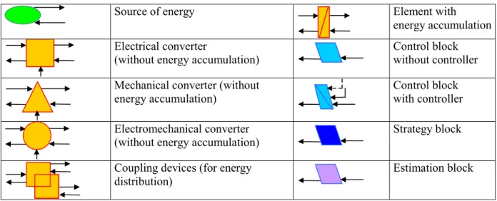
The system is decomposed in basic subsystems in interactions (Table 1): energy sources (green ovals), accumulation elements (orange rectangles), conversion element without energy accumulation (various orange pictograms) and coupling elements for energy distribution (orange overlapped pictograms). Purple pictograms are devoted to estimation bocks. All the elements are connected according to the action and reaction principle using exchange variable (arrows). The product of action and reaction variables between two elements leads to the instantaneous power exchanged.
Table 1: Elements of EMR and of control
Source of energy Element with
energy accumulation Electrical converter
(without energy accumulation)
Control block without controller Mechanical converter (without
energy accumulation)
Control block with controller Electromechanical converter
(without energy accumulation)
Strategy block Coupling devices (for energy
distribution)
Estimation block
Causality principle
As in COG [5], only the integral causality is considered in EMR. This property leads to define accumulation elements by a time-dependant relationship between its variables: its output is an integral function of its inputs. Other elements are described using relationships without time dependence. In order to respect the integral causality specific association rules are defined, but there are taught only in the expert level unit.
Inversion principle
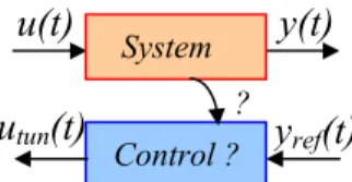
The inversion based control theory has been initiated by COG [5]. The control structure of a system is considered as an inversion of the system modelling: the control has to define the inputs to apply to the system from the desired output (
Fig. 1
). In this method, relationships without time-dependence are directly inverted (with neither control nor measurement). Because the derivative causality is forbidden, a direct inversion of time-dependence relationships is not possible. An indirect inversion is thus made using a controller and measurements. These inversion rules have been extended to EMR (blue pictograms, see Table 1): conversion elements are directly inverted and accumulation elements are inverted using controller. It is another way to located controllers and measurements.y(t)
u(t)
Systemy
ref(t)
Control ?u
tun(t)
?Fig. 1: Inversion-based control principle
EMR and initiation to drive control
A specific unit "Control of electrical drives using EMR" has been introduced in the Master degree of University of Lille. This unit concerns an initiation to drive control using such a graphical tool. The students can improve their skills by choosing a complementary unit "Advanced control of electric systems using EMR". This unit deals with more complex systems (wind energy conversion systems, multi-motor traction systems, hybrid electric vehicles, power systems…) for an expert level. Each unit is associated with 5 ECTS (European Credit Transfer System). Only the expert level is considered in this paper.
The unit is composed of 12 h of lecture on EMR, 20 h of seminars on industrial applications, and 24 h for a simulation project. Each group of student has to simulate different systems. Only a wind energy conversion system is considered in this paper.
The lecture is composed of the following sections:
• Notions of systemic (different description of systems, systemic, internal description and causality, external description and interaction)
• Causal Ordering Graph (basic elements, modeling graphs, inversion-based control methodology, control graphs)
• Energetic Macroscopic Representation (basic elements, elementary conversion between two energy sources, association rules, electromechanical conversion systems)
• Inversion-based control deduced from EMR (inversion of EMR elements, maximum control structure, practical control structures, strategy level)
• Extension to multimachine systems (concept of multimachine systems, coupling elements, inversion of coupling elements)
Seminar on industrial applications illustrate the different concepts:
• EMR and inversion-based control of an automatic subway (performed by an engineer of Siemens Transportation Systems)
• EMR and inversion-based control of a Wind Energy Conversion System (WECS)
• EMR and inversion-based control of a Flexible AC Transmission Systems (FACTS)
• EMR and inversion-based control of a Hybrid Electric Vehicle (HEV)
• EMR and inversion-based control of a ship propulsion system
The studied systems are real industrial applications with different subsystems interconnected. Indeed, this expert level is focused on the associations of sub-systems and the use of ac drives with their control. At the end of the unit the students must be able to model and decompose the system in a physical causal way, and to deduce the control structure of the system by locating controller and measurements or estimations to do.
EMR for the simulation of a wind energy conversion system (WECS)
Studied WECS
The studied system is composed of a rotor blade, a gearbox, a squirrel cage induction machine and a 3-leg voltage source inverter and an equivalent DC bus (
Fig. 2
) [12]. In this project, the dc bus is assumed to be constant. In another project, the connection to the grid is studied.vwind dc bus induction machine Ωgear ucap irect 3-phase rectifier shafts and gearbox blades wind Ωshaft Tim Tblade src31 src 21 src 11 src 22 src 12 src 32 urect13 urect23 iim1 iim2
Fig. 2: Studied Wind Energy Conversion System
Modeling of the WECS
During the WECS seminar, the students learn about the WECS modelling. The following relationships are provided. An EMR is derived from the mathematical models (upper part of
Fig. 4
).Blades — The wind imposes the wind velocity vwind on the blades. The torque Tblade produced by the
blades depends on the wind velocity:
2 2 1 wind T blade C ( , ) SRv T = λ β ρ ( 1 )
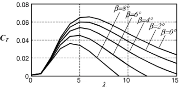
where S is the area swept by the blades, ρthe air density, β the orientation blade and R the blade radius. The torque coefficient CT [12] is a non-linear function of the tip-slip ratio λ which depends on
the wind velocity and the rotation speed Ωshaft:
wind shaft
v RΩ
λ= ( 2 )
The torque coefficient also depends on the blade orientation β (Fig. 3).
0 5 10 15 0 0.02 0.04 0.06 0.08 CT λ β=8° β=6° β=4° β=2° β=0°
Fig. 3: Torque coefficient versus tip-slip ratio of the WECS
from the blade and gearbox torques, Tblade and Tgear: shaft blade gear shaft T T f dt d J Ω =− + − Ω ( 3 )
where J and f are the inertia and the friction coefficient of the equivalent shaft respectively. The gearbox yields the rotation speed Ωgear and torque Tgearas a function of the gearbox ratio kgear and the
induction machine torque Tim:
⎪⎩ ⎪ ⎨ ⎧ = = im gear gear shaft gear gear T k T k Ω Ω ( 4 )
Induction machine — Classical (d,q) dynamic modelling is used to describe the induction machine [15]. First, the transformation [T(θd/s)] expresses stator voltages urect and currents iim in the (d,q) frame:
[
]
[
]
⎪⎩ ⎪ ⎨ ⎧ = = − sdq 1 s / d im rect s / d sdq i ) ( ' T i u ) ( T u θ θ ( 5 )where θd/s is the rotor flux position with respect to the stator stationary frame, since we have chosen
to orient the d axis on the rotor flux for a classical field oriented control.
In this (d,q) frame, the equivalent stator windings impose the stator currents isdq=[isd,isq]t as state
variables in terms of the stator voltages usdq=[usd,usq]t and the e.mf. esdq=[esd,esq]t:
sdq s sdq sdq sdq s dtd i u e R i L = − − ( 6 )
where Rs and Ls are the resistance and cyclic inductance of the stator winding respectively. The
electromechanical conversion yields the machine torque Tim and the e.m.f from the current and the
rotation speed Ωshaft: ) , , i ( f e i k T rd s / d sdq sdq sq rd 1 im ⎪⎩ ⎪ ⎨ ⎧ = = φ θ φ ( 7 )
The rotor flux φrd is given in terms of the d axis current isd: rd sd 3 rd 2dtd k i k φ = +φ ( 8 )
The transformation phase θd/s is deduced as follows: p i k dt d shaft sq rd 4 s / d φ Ω θ = + ( 9 )
where p is the pole pair number. In the previous equations, the coefficients kiare combinations of
isdq usdq esdq isdq irect ucap DC bus iim urect wind svsc Ωgear Tim Ωshaft Tgear Ωshaft Tblade Fblade vwind urect_ref Tim_ref PWM MPPT E M R usdq_ref isdq_ref θd/s β isd φrd isdq_est esdq_est θd/s_est isd_est φrd_est φrd_est φrd_ref estimation (model copy) control (model inversion) isd_ref induction machine (5-9) rectifier (10) shaft (3) blades (1, 2) gearbox (4)
Fig. 4: EMR and inversion-based control of the studied WECS
Voltage-source-converter — The VSC induces a modulated voltage vector urect=[urect13, urect23]t,
from the dc voltage ucap and the switching order vector svsc=[src11, src21, src31]t. Note that only two stator
voltages are used because the third one is a linear combination of the two others. The converter supplies the machine, which reacts via a circulating current vector iim=[iim1,iim2]t. These currents are
also modulated to produce the current irect. A modulation vector mvsc=[m1, m2]t can be introduced to
define the modulation ratio between all variables [16]:
i m i u m u im t vsc rect cap vsc rect ⎪⎩ ⎪ ⎨ ⎧ = = with vsc svsc 1 1 0 1 0 1 m ⎥ ⎦ ⎤ ⎢ ⎣ ⎡ − − = ( 10 )
Inversion-based control of the WECS
Due to the exclusive integral causality, a maximum control structure is deduced from the EMR using inversion-based rules. First, all variables are considered measurable, which yields a control with the greatest number of measurements and controllers. In the second step, simplifications and estimations of non-measured variables are made. Finally, a strategy element is added to define physical references from the power objective [12].
First a tuning chain (Fig. 5) is defined, which begins at the tuning variable that acts on the system (the switching vector svsc) and which ends at the variables that have to be controlled (the machine torque
Tim and flux φrd). We assume that the blade orientation is an external operation.
usdq
isdq urect
svsc
Tim
φ
rdFig. 5: Tuning chain of the WECS
A control scheme is obtained from EMR using inversion rules (lower part of Fig. 4). At this stage all variables are assumed measurable. Then the tuning chain is inverted step by step. Two kinds of inversion are considered.
For conversion element (without energy accumulation), direct inversions are used (simple parallelograms): neither controller nor measurement are required.
For inversion of accumulation elements, a controller is required (crossed parallelograms) and some measurements are also needed.
For example, the inversion of (6) requires a flux controller to provide the current isd_ref from the
reference flux φrd-ref and the measured (or estimated) flux φrd-mesq:
[
rd_ref rd_mes]
ref _
sd C
i = φ −φ ( 11 )
where C[Xref-Xmes] is a controller, which could be PI or other controllers.
In another example, the inversion of (7) leads to the reference current isq_ref from the reference torque
Tim-ref and φrd-ref:
T k 1 i im_ref ref _ rd 1 sq_ref = φ ( 12 )
Simulation of the WECS
The simulation project is composed of 5 sessions of 4h each in a simulation room. A supervisor is available only 1 h per session. An oral presentation including a simulation demonstration has to be done at the end of the unit.
Only the WECS application is presented in this paper. Matlab-SimulinkTM is chosen as simulation
software. The students have three programs at their disposal: an initialisation program containing the WECS parameters (blade, gearbox, IM parameters…), and a Simulink library containing the EMR basic elements.
The objective of the project is to study the WECS using a Maximum Power Point Tracking (MPPT) strategy to extract power from the wind. The students have to build the simulation model of the WECS including the induction machine and the 3-leg voltage source inverter. They have also to determine the whole control structure of the WECS, to tune all controllers and to implement the control part in the simulation software. A field-oriented control can be used for the induction machine. The power electronics is simulated using average values. The MMPT strategy is provided.
In order to organise their simulation, the students are invited to describe EMR of the system and the deduced control. Most of the students (80 %) develop the whole Simulink program (
Fig. 6
). It may be noted that the EMR scheme of Fig. 4 looks like the Simulink scheme. This is helpful for the students for accurately organising their simulation. Different wind profiles are then used (Fig. 7
) and power extraction can be studied for different winds and different blade orientation (Fig. 8
). For more advanced student (10 %), the simulation can be improved by comparisons of different controllers, simulation of the converter using instantaneous values with PWM, or simulation of flux weakening. Moreover, best students can validate their control scheme in real-time using the Hardware-In-the-Loop simulation platform of the Laboratory [17].Fig. 6: Matlab-SimulikTM model of the studied WECS and its control 0 50 100 150 200 250 0 5 10 vwind (m/s) time (s) 15
Fig. 7: Example of wind profile for a 10 m/s average value
0 50 100 150 200 250 0 1 2 3 4 P(MW) time (s) β=0° β=6°
Fig. 8: Extracted power for different blade orientations
Conclusion
The use of EMR is an efficient methodology to develop student skills on drive control. A unified and physical modelling is developed, and inversion rules are used to find the control scheme. By using this intermediary step, they can easily connect other scientific fields such as power electronics, electrical machines, mechanics and automatic control. In the expert level, complex systems are studied to develop scientific skills on drive control. Evaluations of the unit have shown a very good acquisition of fundamentals on drive control. Because of the attractive graphical description, some students choose a final training period in drive control using EMR, both in industry or in academic laboratory. such as in [11], [13].
References
[1] F. Blaabjerg, M. Kazmierkowski, J. Pedersen, P. Thorgersen, M. Tonnes, "An industry/university collaboration in power electronics and drives", IEEE ton Education, vol. 43, no. 1, February 2000, pp. 52-57.
[2] P. Buechner, "New facilities for teaching and research with decentralised electric drive systems", EPE'05, Dresden (Germany), September 2005.
[3] P. Gambôa & all, "Modern Technologies for Experimental Education in Industrial Electronics and Electric Drives", EPE'05, Dresden, (Germany), September 2005.
[4] J. P. Hautier, J. Faucher, “The Causal Ordering Graph”, Bulletin de l'Union des Physiciens, (text in French), vol. 90, juin 1996, pp. 167-189.
[5] J. P. Hautier, P. J. Barre, "The causal ordering graph – A tool for modelling and control law synthesis", Studies in Informatics and Control Journal, vol. 13, no. 4, December 2004, pp. 265-283.
[6] I. Iwasaki, H. A. Simon, “Causality and model abstraction”, Artificial Intelligence, Elsevier, vol. 67, 1994, pp. 143-194.
[7] Z. Rubin, S. Munns, J. Moskowa, “The development of vehicular powertrain system modeling methodologies: philosophy and implementation”, System Automotive Engineering, paper 971089, 1997. [8] H. Paynter, “Analysis and design of engineering systems”, MIT Press, 1961.
[9] A. Bouscayrol, B. Davat, B. de Fornel, B. François, J. P. Hautier, F. Meibody-Tabar, M. Pietrzak-David, "Multimachine Multiconverter System: application for electromechanical drives", EPJ Applied Physics, vol. 10, no. 2, May 2000, pp. 131-147;
[10]P. J. Barrre, A. Bouscayrol, P. Delarue, E. Dumetz, F. Giraud, J. P. Hautier, X. Kestelyn, B. Lemaire-Semail, E. Lemaire-Semail, "Inversion-based control of electromechanical systems using causal graphical descriptions”, IEEE-IECON'06, Paris, November 2006.
[11]Y. Djani, P. Sicard, A. Bouscayrol, "Extension of Energetic Macroscopic Representation to time-varying systems, applications to winder tension control”, IEEE-ISIE'06, Montreal, July 2006.
[12]A. Bouscayrol, P. Delarue, X. Guillaud, “Power strategies for Maximum Control Structure of a wind energy conversion system with a synchronous machine", Renewable Energy, vol. 30, May 2005, pp. 2273-2288. [13]J. N. Verhille, A. Bouscayrol, P. J. Barre, J. C. Mercieca, J. P. Hautier, E. Semail, "Torque tracking strategy
for anti-slip control in railway traction systems with common supplies", IEEE-IAS’04, Seattle (USA), October 2004, vol. 4., pp. 2738-2745.
[14]A. Bouscayrol, A. Bruyère, P. Delarue, F. Giraud, B. Lemaire-Semail, Y. Le Menach, W. Lhomme, F. Locment, “Teaching drive control using Energetic Macroscopic Representation - initiation level”, EPE’07, Aalborg (Denmark), September 2007.
[15]P. Vas, "Vector control of ac machines", Clarendon Press, Oxford, 1990.
[16]P. Delarue, A. Bouscayrol, E. Semail, “Generic control method of multi-leg voltage-source-converters for fast practical implementation", IEEE trans. on Power Electron., vol. 18, no. 2, pp. 517-526, March 2003. [17]A. Bouscayrol, X. Guillaud, P. Delarue, B. Lemaire-Semail, “Energetic Macroscopic Representation and
inversion-based control illustrated on a wind energy conversion systems using Hardware-in-the-loop simulation”, IEEE transactions on Industrial Electronics, to be published in 2009.