STUDY OF WATER ABSORPTION BEHAVIOUR OF NATURAL
FIBRE REINFORCED COMPOSITES
A Thesis Submitted to
National Institute of Technology, Rourkela
In partial fulfilment of the requirement for the degree of
Master of Technology
in
Mechanical Engineering
By
NANDKISHOR SHARMA
(Roll no. 212me1283)
Department of Mechanical Engineering
National Institute of Technology
Rourkela-769008
India
STUDY OF WATER ABSORPTION BEHAVIOUR OF NATURAL
FIBRE REINFORCED COMPOSITES
A Thesis Submitted to
National Institute of Technology, Rourkela
In partial fulfilment of the requirement for the degree of
Master of Technology
In
Mechanical Engineering
(Specialisation-Machine Design and Analysis)By
NANDKISHOR SHARMA
(Roll no. 212me1283)
Under the guidance and supervision of
Prof. S. K. ACHARYA
Department of Mechanical Engineering
National Institute of Technology
Rourkela-769008
India
i
DEPARTMENT OF MECHANICAL ENGINEERING NATINAL INSTITUTE OF TECHNOLOGY ROURKELA, ORRISA INDIA- 769008
CERTIFICATE
This is to certifythat the thesis entitled “Investigation of mechanical properties of luffa cylindrica reinforced epoxy composite for different environmental conditions” submitted to the National Institute of Technology, Rourkela by Nandkishor Sharma, Roll No. 212ME1283 for the award of the degree of Master of Technology in Mechanical Engineering is a record of bonafied research work carried out by him under my supervision and guidance. The results presented in this thesis hsa not been, to the best of my knowledge, submitted to any other University or Institute for the award of any degree or diploma.
The thesis, in my opinion, has reached the standards fulfilling the requirements for the award of the degree of Master of Technology in accordance with regulations of the Institute.
Place: Rourkela (Dr. S. K. Acharya)
Date:
Professor
Department Mechanical Engineering
National Institute of Technology
ii
ACKNOWLEDGEMENT
I would like to express my gratitude to my supervisor Prof. S.K. Acharya for his guidance, encouragement, moral support and affection through the course of my work.
I am also thankful to Prof. Sunil Kumar Sarangi, Director, NIT, Rourkela who
took keen interest in the work. My special thanks to Prof. K.P Maity, Head of Mechanical Engineering Department and all staff members of the mechanical department
for their timely help in completion of this work.
I am also thankful to Mrs. Niharika Mohanta of mechanical engineering for her
support & help during my experimental work.
This work is also the outcome of the blessing guidance and support of my father
and mother Mr. Sharda Prasad and Mrs. Binda Devi this work could have been a distant dream if I did not get the moral encouragement from them.
I feel pleased and privileged to fulfil my parent’s ambition and I am greatly
indebted to them for bearing the inconvenience during my M-Tech course. I express my
appreciation to my friends for their understanding, patience and active co-operation
throughout my M-Tech course finally.
iii
DECLARATION
I hereby declare that this submission is my own work and that, to the best of my knowledge
and belief, it contains no material previously published or written by another person nor
material which to a substantial extent has been accepted for the award of any other degree or
diploma of the university or other institute of higher learning, except where due
acknowledgement has been made in the text.
iv
ABSTRACT
Environmental perception today encourages empiricism worldwide on the learning of plant or natural fibre reinforced polymer composite and cost efficient alternative to synthetic fibre reinforced composites. The accessibility to natural fibers and simplicity in manufacturing have persuaded researchers to aim for locally existing low cost fibers and to investigate their possibility of reinforcement intensions and up to what extent they can satisfy the essential detailing of superior reinforced polymer composite intended for different application program. Natural fibre represents a superior biodegradable and renewable alternative to the most popular synthetic reinforcement, i.e. glass fibre possessing high mechanical properties and low cost. Regardless the curiosity and environmental request of natural fibers, there usage is restricted to non-bearing uses, because of its lower strength than that of synthetic fibre reinforced polymer composite. The stiffness and strength limitations of bio composites can be chased by operational arrangement by placing the fibers at particular locations to have higher strength performance. Research regarding preparation and properties of polymer matrix composite (PMC) replacing the synthetic fibre with natural fibre like Jute, Sisal, Jute, Bamboo, Pineapple, Bagasse and Kenaf were carried out. Renewable, environmental friendly, low cost, lightweight and high specific mechanical performances are the advantages of these plant fibres over the glass fibre or carbon fibre. Composites are exciting materials which are finding increasing application in transportation, aerospace, defence, communication, sporting, electronics and number of other commercial and consumer products. Composite materials have become one of the fastest growing research and development areas of Material Science because of their high potential. In current years there is swift growth in the arena of fibers, matrix, materials, processing, boundary structure, bonding and their characteristics on the final properties of composites. The technological developments in composite materials help in meeting the global industrial demand for materials with improved performance capabilities.
Keeping this in view the present work has been under taken to develop a polymer matrix composite (epoxy resin) using Luffa Cylindrica fibre and to study its moisture absorption behavior and mechanical properties. The composite are prepared with different volume fraction (number of layers) of Luffa Cylindrica fibre.
v
TABLE OF CONTENTS
Certificate ... i Acknowledgement ... ii Declaration... iii Abstract ………..………...iv Table of Content ... vList of Tables ... viii
List of Figures ... ix Chapter-1 Introduction 1.1 Background 1 1.2 Composites 2 1.2.1 Why a composite? 2 1.2.2 What is a composite? 3 1.2.3 Classification of composites 4 1.2.3.1 Particulate composites 6 1.2.3.2 Fibrous composites 6
1.3 Components of a Composite Material 6
1.3.1 Role of matrix in a composite 6
1.3.2 Materials used as matrices in composites 7
1.3.2.1 Bulk-Phases 7
1.3.2.2 Reinforcement 7
1.3.2.3 Interface 7
1.4 Types of Composite Materials 8
1.4.1 Fibre-Reinforced Composites 8
vi
1.4.1.2 Discontinuous or short fiber composite 9
1.4.2 Laminate Composites 9
1.5 Natural Fiber Composites: (Initiative in Product Development) 10
1.5.1 Applications of natural fibre reinforced composites 11
Chapter 2 Literature Survey 2.1 Natural Fibers: Source and Classification 14
2.2 Chemical Composition of Natural Fibers 16
2.2.1 Cellulose 16 2.2.2 Hemicelluloses 16 2.2.3 Lignin 17 2.2.4 Pectin 17 2.3 Matrix Material 18 2.3.1 Thermo-sets 19
Chapter-3 Mechanical Characterization of Luffa Cylindrica Fibre Epoxy Composite 3.1 Introduction 21
3.2 Chemical Modification of Fibre 24
3.2.1 Methods of Chemical Modifications 3.2.1.1 Alkaline treatment 25
vii
3.3.1 Preparation of Luffa Cylindrica Fibre Mats 26
3.3.2 Epoxy resin 26
3.3.3 Composite preparation 26
3.4 Study of Environmental Effect 28
3.4.1 Moisture absorption test 28
3.4.2 Mechanical testing of samples 29
3.4.2.1 Tensile test 29
3.4.2.2 Flexural test 31
3.4.3 Results and discussion 32
3.4.3.1 Moisture absorption behaviour 32
3.4.3.2 Measurement of diffusivity 33
3.4.3 Effect of moisture absorption on Mechanical properties 34
3.5 Conclusions 35
viii
LIST OF TABLES
Table No. Title Page No.
1.1 Classification of composite 5
2.1 Properties of glass and natural fibers 15
2.2 Comparison between Natural fibre and Glass fibre 18
3.1-3.24 Variation of weight gain and thickness swelling of untreated and treated Luffa Cylindrica fibre epoxy composite (flexural and tensile) with immersion time expose at distil and saline water environment.
ix
LIST OF FIGURES
Figure No. Title Page No.
1.1 (a-e) Different types of Composite 10
1.2 Photographs of Luffa Cylindrica plant and luffa mat 12
2.1 Classification of natural fiber that can be used as reinforcements
15
2.2 Chemical structure of DGEBA 19
3.1 Mould used for fabrication 27
3.2 (a) Flexural test samples 27
3.2 (b) Tensile test samples 28
3.4 (a) UTM machine sample unloaded for tensile testing 30
3.4 (b) UTM machine sample loaded for tensile testing 30
3.5 UTM machine sample unloaded for flexural testing 31
3.6 to 3.13 Variation of flexural and tensile strength with different layers of Luffa Cylindrica fibre epoxy composites (untreated and treated) exposed to distil water environment
x
3.14 to 3.21 Variation of thickness swelling of untreated and treated Luffa Cylindrica fibre epoxy composite (tensile and flexural) with immersion time expose to saline and distil water environment
66-69
3.22 to 3.29 Variation of weight gain of untreated and treated Luffa Cylindrica fibre epoxy composite (tensile and flexural) with immersion time expose to saline and distil water environment
70-73
3.30 to 3.33 Maximum moisture absorption of untreated and treated Luffa Cylindrica fiber epoxy composite (tensile and flexural samples) versus fiber loading in both the environments
74-75
3.34
3.35
Example Diffusion curve fitting for Luffa Cylindrica fibre epoxy composites under different environment
Example Plot of percentage of moisture absorption versus square root of time for calculation of Difusivity
76
3.36 to 3.43 Variation of log (Mt/Mm) with log t for untreated and treated Luffa Cylindrica fiber epoxy composites (tensile and flexural) exposed to distil and saline water environment
Chapter
1
NIT ROURKELA Page 1
Chapter-1
1.1
BACKGROUND
It is a platitude that technological advances depends on fosters in the sector of materials. If sufficient materials to bear the service loads and conditions are not available then one does not have to be a skilful to realize the most advanced turbine or air-craft pattern. Whatsoever the field may be, the ultimate restriction on progression is to be governed by materials. Composite materials in this regard signify a big step in the constant accumulation of optimization in materials. Composites are mixture of two or more materials such as reinforced plastics, metals, or ceramics. The reinforcements may be in the form of fibers, particles, whiskers or lamellae and are embedded in a suitable matrix, thereby providing a material that contains the most useful properties of the constituents. High structural strength, glass fibre reinforced plastics were developed in the early 1940’s and the application of reinforced plastics composites, the glass fibre provides strength and stiffness while the plastic matrix provides the temperature capabilities of the composite. Initially the glass fibres were incorporated in a polyester matrix which could withstand temperature up to 200⁰C. They were applied in car bodies, appliances, boats etc., because of their light weight and mitigate of production. Intricate composites parts can be made by injection moulding. Polymer matrices are usually thermosets such as epoxies. Later, resins which can withstand high temperatures, of the order of 300⁰C were developed such as polyamides. Other thermo setting resins include benzocylobutene – bismaleimides. Advanced composites are manufactured by using the above polymers with reinforcements of stronger fibres such as aramid and carbon. As a result advanced composites are finding increasing applications in aircraft, automotive industry, etc. In order to reduce the manufacturing time, thermoplastics polymers such as polyether – ether ketone (PEEK) have been developed. The plastic requires only a short revelation to heat to soften the plastics, thereby allowing faster processing of the composite.
The limitations of the polymer matrix composites at high temperatures can be overcome by the use of metal matrix composites. These composites are processed by powder metallurgy methods, by penetration of the molten metal with the fibre or particulate or by mixing particulates with molten metal. Plasma spraying, vapour deposition, plasma spraying or
NIT ROURKELA Page 2 electro deposition followed by dispersal bonding are the other methods of fabrication. Metal matrix composites are discovering applications in defence, aerospace, automotive and electronic packaging. In addition to metal matrix composites, intermetallics such as nickel, iron, titanium and niobium aluminides matrix composites are also being actively considered for use at elevated temperatures.
The temperature range of application of metal matrix composites is lower than that of ceramic matrix composites. Ceramic matrices such as zirconia, alumina, silicon nitride, silicon carbide, mullite etc. can be reinforced with ceramic continuous fibres, whiskers or particulates. Carbon-carbon composites is a ceramic composite which can retained its strength at temperatures up to 2500⁰C and is applied as a critical component in aerospace. Adduce composites have both structural and functional applications. Adaptable composites will have the potentiality not only of load bearing but will also have an agile and flexible response to structure functional conditions. These advanced growths will increase and sensing potential of structures such as vertical tails, aircraft bulkheads, intrinsic avionics, smart skins and antenna systems. For elevated temperatures, smart metal matrix composites with fibre optic sensors in a titanium matrix composite are being boisterously considered.
The study of composites materials is a multifaceted memorandum as it is difficult for any individual to grasp the compound behaviour of many of the current composites. This field provides lot of analytical problems for experimental schedules, theoreticians for research workers and new defiance for designers. Even the technologically advanced fibre glass reinforced plastics in the 1940s require a information of ceramics, glass technology, surface science, polymers, modelling, design and analysis in order to redeem the properties, structure and purpose of the final composite product.
1.2
COMPOSITES
1.2.1 Why a composite?Over the last three decades years composite materials, plastics and ceramics have been the ascendant developing materials. Numerous uses of composite materials have grown evenly, pervasive and dominant new markets interminably. Modern composite materials comprise a
NIT ROURKELA Page 3 significant amount of the engineering materials market varies from commonplace products to worldly niche applications.
Although composites have already manifested their value as weight reduction materials, the existing job is to make them cost productive. The endeavours to yield economically smart composite components have evolved in some unorthodox manufacturing techniques currently being used in the composite industries. It is vibrant, specifically for composites, that the development in manufacturing technology only is not sufficient to overcome the cost hurdle. It is important that there must be an unsegregated implementation in material processing, designing, manufacturing, tooling, quality assurance and even programmes organisation for composites to make them competitive with metals.
Further, need of composites for lighter building materials and more shock resilient structures has placed high prominence on the usage of fresh and innovative materials that not only reduces weight but also assimilates the shock and vibration by tailored microstructures. Composites at the present are largely used for rehabilitation or strengthening of preceding structures that need to be render in order to make them seismic resilient, or to restore damage due to seismic activities.
The properties of composite material can be designed by bearing in mind the structural aspects, unlike conventional materials (e.g., steel); both material and structural design operations are there in the plan of a structural component using composites. Properties of composites such as thermal expansion, stiffness etc. can be assorted frequently over a wide range of values beneath the designer control. Correct assortment of reinforcement category allows concluded product features to be customized nearly every specific engineering necessity.
1.2.2 What is a composite?
A typical composite material consists of two or more materials (bonded and mixed) on macroscopic rules which are not soluble in each other.
Normally, a composite materials are composed of reinforcement (fibers, flakes, particles and fillers) implanted in a matrix such as polymers, metals, or ceramics. The function of matrix is to hold the reinforcement to form the craved shape while the reinforcement ameliorates the whole mechanical properties of the matrix. The new
NIT ROURKELA Page 4 combined material possesses better strength than the each individual material in a system, when designed correctly.
As stated by Jartiz, [1] Composites are such a universal material which can provide such properties that are not possible to obtain from any distinct material. Composites possess cohesive structures brought up by physically amalgamating two or more suited materials, but different in composition and characteristics and occasionally in configuration.
Kelly [2] evidently emphasises that the composites should not be considered as just combination of two different materials. In wider sense; the amalgamation has its particular characteristic properties. In relations of strength, heat resistant or specific other advisable quality, it is far better than the components taken individually or fundamentally different from both of them.
Berghezan [3] defines as “The composites are amalgamated materials which differ from alloys by the fact that the individual components in composites preserve their characteristics but are combined in such a way so as to take advantage of their features only and not of their limitations”, in order to obtain a much better material.
Van Suchetclan [4] describes composite materials as diverse materials which consist of two or more solid states that are in constricted interaction with each other. He also stated that composites can be also contemplated as homogeneous material on a microscopic level in a way that whichever part of it is separated will have the physical property same as the composite.
1.2.3 Classification of Composites
Composite materials perhaps categorized in distinct ways [5]. Arrangement based on the geometry of a characteristic unit of reinforcement is suitable since it is the geometry of the reinforcement which is liable for the mechanical properties and better presentation of the composites. The classification is presented in Table1.1. The two broad classes of composites are:
(i) Fibrous composites (ii) Particulate composites
NIT ROURKELA Page 5
Table-1.1 Classification of composite
Composite materials
Fibre reinforced composites Particle reinforced composites
Preferred orientation Random orientation Single layer composites Multi layered composites Laminates Hybrids Continuous fibre reinforced composites Discontinuous fibre reinforced composites Random orientatio n Preferred orientatio n Unidirectional reinforcement Bi-directional reinforcement
NIT ROURKELA Page 6 1.2.3.1 Particulate Composites
The name only specifies, that the reinforcement posses particle nature. It may be cubic, spherical, tetragonal, or of any regular or irregular shape, but it is approximately equiaxial. In common, particulates are not much productive in enhancing fracture resistance but it increases the stiffness of the composite to a restricted amount. Particle fillers are largely used To upgrade the properties of matrix materials such as to improve the electrical and thermal conductivity, to improve presentation at high temperatures, abrasion resistance, decrease friction, improve wear, increase surface hardness, increase machinability and lessens shrinkage.
1.2.3.2 Fibrous composites
Fibres are well known for its length and cross-section ratio i.e. their length is much greater than that of cross-sectional dimensions. The reinforcement dimension plays a significant role in governing its potentiality of contributing properties to the composites. Since reinforcement possessing a long dimension depresses the growth of developing cracks usual to the reinforcement that might results to wreck, especially with brittle matrices as fibers are very effectual in enhancing the fracture resistance of the matrix.
1.3 COMPONENTS OF A COMPOSITE MATERIAL
In its most basic form a composite is the element which comprises of two or more elements (at least two elements) that are binded together to produce a different material which produces enhanced properties that are better and different to the properties of the individual elements. Usually composites comprises of reinforcement and a matrix, incorporated mainly to raise the stiffness and the strength of the matrix.
1.3.1 Role of matrix in a composite
Numerous materials when are in a fibrous form display very high strength but in order to attain these properties the fibers must be joined by an acceptable matrix. The role of matrix is to separates the fibers from each other in order to avert abrasion and development of fresh surface flaws and to stick the fibers in place by acting as a bridge. A quality matrix must possess the capability to transfer the load onto the fibers, deform easily under applied load.
NIT ROURKELA Page 7 In case of laminates [6] the nature of bonding forces indicates that upon initial loading there is a proneness for the adhesive bond between the matrix and reinforcement to be failed. The frictional forces between them portrayal for the high strength properties of the laminates.
1.3.2 Material used as matrices in composites
1.3.2.1 Bulk-Phases (a) Metal Matrices
(b) Polymer Matrices
(c) Ceramic Matrices
1.3.2.2 Reinforcement
In a composite material the purpose of the reinforcement is basically to increase the mechanical properties of the neat resin structure. The properties of the composite are affected differently by different fibers used in it as these fibers have different properties. For various applications, the fibres are required to be organised into the structure of sheet, known as a fabric, in order to make handling possible.
1.3.2.3 Interface
The important feature of interface is that its properties are not rendered by any component in the system on isolation. It is a bounding zone at which disturbances occurs, it can be mechanical, chemical, physical etc. It is required that fibre must be wetted by the matrix material and in order to improve this wettability coupling agents are used frequently. Increase in the interface surface area is only possible when the fibre is well ‘wetted’. The applied load must be effectually transferred to the fibers from the matrix through the interface to get the advisable properties and this concludes that the interface should be large and the fibers and matrix must be joined strongly.
NIT ROURKELA Page 8 1.4 TYPES OF COMPOSITE MATERIALS
The composite materials are classified into the following categories as shown in Figure-1.1 (a - e).
1.4.1 Fibre-reinforced composites
Because of intrinsic high specific strength and stiffness these composites are universally used in numerous industrial applications. These composites are acquiring high potential in tribological applications also as they possess brilliant structural presentation. Fiber reinforced composites materials comprises of fiber of high strength in or bonded to a matrix with discrete interfaces between them [4, 5]. In this form physical and chemical identities are retained by both fibres and matrix. Yet they produce an amalgamation of properties which is difficult to achieve with either of the composite constituents individually. In general, the role of fibers is to carry load, whereas the role of matrix is to keeps them in the crave position and alignment [5, 6].Fibrous composite can be further classified into two groups: continuous (long) fiber composite and discontinuous (short) fiber composite.
1.4.1.1 Continuous or long fiber composite
Geometrically, a continuous fibre is distinguished as it possesses a high length to diameter ratio. It also comprises of reinforcement matrix by a disseminate phase in the type of continuous fibre. These are basically tougher and stiffer when compared to matrix i.e. bulk phase material. Based on the manner in which fibers are stuffed within the matrix, it is again subdivided in to two categories: (a) unidirectional reinforcement and (b) bidirectional reinforcement. In unidirectional reinforcement, the fibers are aligned in one direction only where as in bidirectional reinforcement the fibers are aligned in two directions either at some desired angle (angle-ply) or at right angle to one another (cross-ply). When fibers are continuous and large, they transmit certain degree of anisotropy to the properties of the composites especially when they are oriented. Multi-axially oriented continuous fibre composites are also exhibit near isotropic properties.
NIT ROURKELA Page 9 1.4.1.2 Discontinuous or short fiber composite
Short-fiber reinforced composites comprises of a reinforced matrix by a distributed phase in the type of discontinuous fibers which are having, length < 100×diameter. The low cost, proficiency of fabricating intricate parts, and isotropic nature are sufficient to make the short fiber composites the material of selection for large-scale production. Accordingly, the short-fiber reinforced composites have profitably established its place in lightly loaded component production. Furthermore the discontinuous fiber reinforced composite divided into: (a) biased or preferred oriented fiber composite and (b) random oriented fiber composite. In the prior, the fibers are oriented in pre-decided directions, whereas in the later type, fibers remain randomly. The alignment of short fibers can be done by scattering of fiber on to given plane or inclusion of matrix in liquid or solid state before or after the fiber displacement.
1.4.2 Laminate Composites
Laminate Composites consists layers of material held together by matrix. Mainly, these layers are organized alternatively in order to provide a better bonding between the reinforcement and the matrix. According to the end use of the composite these laminates can have uni- directional or bi-directional orientation of the fiber reinforcement. The different types of composite laminates are angle-ply, unidirectional, symmetric laminates and cross-ply. A blended laminate can also be fabricated by the use of alternate constituent materials or of the same material with alternate reinforcing design. In most of the applications of laminate composites, man-made fibers are used because of their good amalgamation of physico-mechanical and thermal behaviour.
NIT ROURKELA Page 10 (a) Continuous fiber (b) Particulate composites (c) Flake composites
composite
(d) Random fiber (short fiber) Composite (e) Laminate Composite Figure-1.1 (a-e) Different types of Composite
1.5 NATURAL FIBER COMPOSITES: Initiative in Product Development
The cost effective option to synthetic fibre reinforced composites and the interesting studies of plant or natural fibre inspires the researchers to make advances in the field of composites. Ease in access and built-up simplicity of natural fibre have convinced these researchers to try natural fibres which are available locally and to study their practicability of reinforcement motives. These are also studied to have the information that up to what limit they can fulfil the desired specifications and properties for various uses. Natural fibre appears as a good renewable and biodegradable substitute to most of the synthetic fibre such as glass fibre.
Vegetables, animal, mineral fibers etc. fall under the area of natural fibre. Generally it is referred as wood and agro based fibre, leaf, stem and seed fibers in the composite engineering. A natural fibre frequently contributes to the structural presentation of plant and
NIT ROURKELA Page 11 they can deliver substantial reinforcement, when used in the production of plastics composites.
Is curtailed to non-bearing applications because of their bring down strength compared to synthetic fibre reinforced polymer complex in malice of the interest and environmental appeal of natural fibers. By the sense of positioning the fibers in particular locations for maximum strength presentation, the limitations in stiffness and strength of bio composites can be succeeded.
Accordingly vast studies on construction and properties of polymer matrix composite (PMC) substituting the synthetic fibre with natural fibre like Jute, Pineapple, Sisal, Kenaf, Bamboo, luffa cylindrica, ipomea carnea and Bagasse were executed [7-12]. Above natural fibers have numerous advantages over the glass fibre or carbon fibre such as renewable, low cost, lightweight, high specific mechanical performance.
1.5.1 Applications
1. Automobile industry: For inner and outer parts fibre reinforced plastics are used. These are used in industries because of their advantages over the glass fibre reinforced composites such as cheaper, environment friendly, etc. By these fibers cars according to End-of-Life directive can be developed as the resulting products from these composites can be re-used and do not have to be land filled unlike glass fibre. Because of their softness and non-harsh behaviour unlike glass fibers they are used in interior automotive uses and are having advantages of not injuring the passengers.
2. Packaging industry: In these industries these are used for light weight pallets. Weight reduction is the chief reason for using composite material in place of wood, which saves fuel during transportation.
3. Consumer products: Natural fibre can be used for any injection moulded product. Reduction of plastic use, flame retardancy and re-use. Examples are household appliances like cell phones, refrigerators and computers. They are less vulnerable to fire due to the fibre structure of composite. Also the high fibre loads results in major material cost reduction.
NIT ROURKELA Page 12 4. Building and construction industry: In these they are used for roofings and instance
profiles. Cost reduction, re-use and flame retardancy are the advantages. 1.5.2 Luffa cylindrica as a natural fiber
Numbers of potential natural resources are there, which India has in abundance. Most
of which comes from the forest and agriculture.
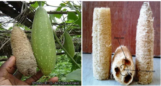
Fig 1.2 (a) Fig 1.2 (b)
Fig 1.2 (c) Fig 1.2 (d)
Fig. 1.2 The Luffa cylindrica plant (a), the inner fiber core (b) and the outer core open as a mat (c, d).
NIT ROURKELA Page 13 Luffa cylindrica, locally called as ‘Sponge-gourds’ is that natural resource whose capability as fiber reinforcement in polymer composite has not been explored to date. The fibrous cords are liable in a multidirectional array resulting in a natural mat in ligneous netting system possess by ‘Sponge gourds’. It comprises 62% cellulose, 20% hemicellulose and 11.2% lignin [1]. The sponge-gourd (Luffa Cylindrica) plant with fruit which belongs to the curcubitacea family is shown in Fig. 1.1(a).
The main objective of this project is to prepare a PMC using luffa fiber as reinforcement and epoxy as matrix material and to study its moisture absorption characteristics under different environmental conditions and then to find its mechanical properties i.e.; tensile and flexural strength. Out of the available manufacturing techniques, we have chosen hand-lay-up method to construct the composite. Then the composites were manufactured by varying the no. of layers of fiber i.e.; single, double and triple layers composite using these techniques. The surface of fracture and worn out samples have been studied using Scanning Electron Microscope (SEM) to have an idea about the fracture behaviour of the composite.
In the 2nd chapter, detailed discussion on reinforcement material, outline of fabrication processes and effort related to current investigation available in literature are presented.
In the 3rdchapter, the effect of environment on mechanical properties of both treated and untreated fiber reinforced composite along with moisture absorption characteristics have been presented.
Chapter
2
NIT ROURKELA Page 14
Chapter-2
2.1
NATURAL FIBERS: Source and Classification
Growing environmental awareness has activated the researchers worldwide to enhance and utilize materials that are companionable with the environment. In the procedure natural fibers have become suitable options to traditional synthetic or manmade fibers and have the prospective to be used in cheaper, more sustainable and more environment friendly composite materials. Natural organic fibers can be obtained from either animal or plant sources. Most of the useful natural textile fibers are obtained from plant, with the anomaly of wool and silk. All plant fibers comprises of cellulose, whereas protein act as a chief content of fibers of animal origin. Hence, the natural fibers are categorized on the basis of their origin, whereas the plant fibers can be further classified on the basis of plant parts from which the parts are originated. An overview of natural fibers is showed in Figure-2.1 [13].
Normally, plant or vegetable fibers are cast to reinforce polymer matrices and a categorization of vegetable fibers is given in Figure-2.1 [14]. Plant fibers are a renewable resource and have the capability to be recycled. The plant fibers leave slight residue if they are burned for disposal, returning less carbon dioxide (CO2) to the atmosphere than is separated during the plant’s growth.
The chief driver for switching natural fibers for glass is that they can be grown with lesser cost than glass. The price of glass fiber is around Rs. 300.0/- per kg and has a density of 2.5 gm/cc. On the other hand, natural fiber costs Rs. 15.0/- to 25.0/- per kg and has a density of 1.2-1.5 gm/cc. As can be seen from Table-2.1 [13], although the modulus is of the same order of magnitude, the tensile strength of natural fibre is considerably lower than the glass fibers. On the other hand, when the specific modulus of natural fibers is measured, the natural fibers show values that are similar to or even better than glass fibers. Material cost savings, suitable to the use of natural fibers and high fiber filling levels, coupled with the benefit of being non-abrasive to the mixing and moulding tools make natural fibers a thrilling outlook. These reimbursement mean natural fibers could be used in many applications, including building, automotive, household appliances, and several other applications.
NIT ROURKELA Page 15 Table-2.1 Properties of glass and natural fibers
Mechanical Properties
Fibers
E-glass Hemp Flax Jute Sisal Coir Ramie
Density (gm/cc) 2.25 1.48 1.4 1.46 1.33 1.25 1.5 Tensile Strength (MPa) 2400 550-900 800-1500 400-800 600-700 220 500 Young’s Modulus (MPa) 73 70 60-80 10-30 38 6 44 Specific Modulus (MPa) 29 - 26-46 7-21 29 5 2 Failure Strain (%) 3 1.6 1.2-1.6 1.8 2-3 15-25 2 Moisture Absorption (%) - 8 7 12 11 10 12-17
Figure-2.1 Classification of natural fiber that can be used as reinforcements.
Natural plant fibre
Non-wood natural fibres Wood fibres
Straw fibres Bast fibre fibers Leaf fibers Seed/Fruit fibres Grass fibre fibers Hemp Flax Jute Kenaf Ramie Corn Wheat Rice Wheat Rice Sisal Henequen Pineapple Bamboo Switch grass Miscanthus Cotton Coir Soft wood Hardwood
NIT ROURKELA Page 16
2.2 CHEMICAL COMPOSITION OF NATURAL FIBERS
The component of any natural fiber differs with variety, area of production and origin, maturation of plant. The major component of a fully developed natural fiber cell walls are cellulose, hemicellulose, lignin and pectin. These –OH including polymers are distributed all the way through the fibre wall [15].
2.2.1 Cellulose
The long thin crystalline micro-fibrils in the secondary cell wall are prepared of cellulose. It is the reinforcing material and is in charge for better mechanical strength of fibers. Chemically, cellulose is explained as a highly crystalline section alternating with regions of non-crystalline or amorphous cellulose [16, 17].
The glucose monomers in cellulose form hydrogen bonds both inside its own chain (intramolecular) forming fibrils and with neighbouring chains (intermolecular), creating micro-fibrils. These hydrogen bonds lead to development of a linear crystalline structure with high rigidity and strength. The amorphous cellulose sections have a lower frequency of intermolecular hydrogen bonding, thus revealing reactive intermolecular -OH groups to be bonded with water molecules. Amorphous cellulose have tendency to bond with water hence they are considered as hydrophilic in nature. On the contrary, crystalline cellulose possess very low accessible intermolecular –OH and thus it possess far smaller amount hydrophilicity than the amorphous cellulose. Crystalline micro-fibrils have accessible –OH available on the surface of the structure and also have closely filled cellulose chains in the fibrils. Only extremely strong acids and alkalis may go through and transform the crystalline lattice of cellulose.
2.2.2 Hemicelluloses
Hemicelluloses vary from cellulose in three dissimilar ways.
1. In contrast with cellulose (including 1,4-β-D-glucopyranose units only) they have some assorted sugar units.
2. They reveal a considerable degree of chain branching, while cellulose is a linear polymer.
NIT ROURKELA Page 17 3. The standard of polymerization of local cellulose is ten to hundred times
greater than the hemicelluloses.
The element of hemicelluloses differs from plant to plant unlike cellulose. It includes substituent like -COCH3 groups and glucoronic acid.
Chiefly the acid residue close to hemicelluloses makes it highly hydrophilic and raises the fiber water uptake, which increases the danger of microbiological fiber deprivation. It has been found that at lower temperatures hemicelluloses thermally degrade more (150-180°C) than cellulose (200-230°C) [18].
2.2.3 Lignin
Collectively with cellulose, it is the superabundant and significant polymeric organic substance in the world of plant. For trees of 100 meters height to stay upright lignin plays a major role as it multiplies the compression strength of plant fibers by sticking the fibers collectively to form a stiff structure. Lignin is basically a chaotic, polyaromatic, and cross-linked polymer emerging from the free radical polymerizations of two or three monomers structurally associated to phenyl-propane [19]. The lignin matrix is consequently similar to a thermoset polymer in conservative polymer terminology. The disbanding of lignin using chemicals aids fiber separation. When reveal to ultraviolet light, lignin undergoes photochemical deprivation. The lignin seems to perform like a matrix material contained by the fibers, making stress transfer on a micro-fibril scale and single fiber scale achievable.
2.2.4 Pectin
Pectin, otherwise called pectic polysaccharides, is rich in galacturonic acid. A few different polysaccharides have been distinguished and described inside the pectic gathering. Homogalacturonans are direct chains of α-(1–4)-joined D-galacturonic acid.
Pectin is a confounded stretched structure of acidic structural polysaccharides, established in fruits and bast fibers. Of all the compound in plant fibres pectin is the most hydrophilic in nature as it contains carboxylic acid groups and is basically debased by defibration with organisms [16]. Pectin together with hemicelluloses and lignin existing in natural fibres can be hydrolysed at elevated temperatures.
NIT ROURKELA Page 18 Table- 2.2Comparison between Natural Fibre and Glass Fibre
Natural Fibre Glass Fibre
Density Low Twice that of Natural fibre Cost Low Low, but higher than Natural
fibre
Renewability Yes No
Recyclability Yes No
Energy Consumption Low High Distribution Wide Wide
CO2 neutral Yes No
Abrasion to Machining No Yes Health risk when inhaled No Yes
Disposal Biodegradable Not Biodegradable
2.3
MATRIX MATERIAL
High strength properties are shown by various materials only when they are in fibrous form and these properties are attained if the fibre is bonded by an appropriate matrix. Matrix segregates the fibers from each other so as to avoid abrasion and establishment of fresh surface defect and behave as a link to grip the fibres in a particular position. Under applied load, matrix tends to possess the capability to deform quite easily, uniformly distribute concentrated stress and transfers the load to the fibers effectively but in order to get these the matrix should be of good quality.
A study of the nature of bonding forces in laminates [20] specifies that upon initial loading there is an affinity for the adhesive bond into them to report for the high strength properties of the of the laminates.
In order to transfer the load to the fibers through matrix and to guard them from handling and environments the polymer matrix should sticks the fibers together. Polymer or resin systems are used to manufacture advanced Polymer Matrix Composites (PMCs) is of two primary types, thermosets and thermoplastics.
NIT ROURKELA Page 19 2.3.1 Thermosets
Much of the initial work used thermosetting resins as matrix material for composite construction. Products like tufnol which is shaped using cotton fibres and epoxy resin, have been available for some time, possessing good stiffness and strength [21]. In the past few years there has been transformed interest in these products for use in automotive applications. To attain reinforcing consequences in composites it is essential to have decent adhesion across the resins and fiber. Epoxy and phenolic thermosetting resins are well-known to be capable to form covalent cross-links with plant cell walls along -OH groups. Production of composite can be achieved by means of low viscosity epoxy and phenolic resins that cure at room temperature. In accumulation epoxy resin does not yield volatile products throughout curing which is most advisable in construction of void free composites. Although epoxy resins are comparatively more expensive than polyester, they possess high potential for the development of added value plant fiber composites, whereas long fibres at a high content are mandatory.
Figure-2.2 Chemical structure of DGEBA
For curing agents of epoxy resins primary and secondary amines are mainly used. On the whole, reaction rate of an amine with an epoxide is dominated by the steric encumbrance and the electron donating groups that exists in the amine.
The merits of epoxy resins are low polymerisation shrinkages unlike polyesters during cure, excellent resistance to chemicals and solvents, good mechanical strength, and excellent adhesion to fibres. The epoxy molecule consist of two ring groups at its centre, that have the capability to absorb both thermal and mechanical stresses better than the linear groups, giving epoxy resin very good strength, toughness, stiffness and heat resistance.
The main demerits of the epoxy resins are that they need long curing times and, for the most part, their mould discharge qualities are poor. The epoxy resins are categorized by
NIT ROURKELA Page 20 high adhesive strengths. After reviewing the stimulating literature accessible on the natural fiber composite hard work are put to recognise the basic needs of the emerging composite industry. The decisions drawn from this is that, the achievement of merging vegetable natural fibers with polymer matrices results in the improvement of mechanical properties of the composite associated with the matrix material. These fillers are cheap and non-toxic and can be acquire from renewable source and are effortlessly recyclable. Furthermore in spite of their low strength, they may results into composite possessing high specific strength due to their low density.
Thus significance of this work is to prepare polymer matrix composites (PMCs) using Luff Cylindrica fiber as reinforcement material. To increase the interfacial strength among the fibre and the matrix, the surface alteration of the fibre has to be done by chemical treatment. The composite is then being subjected to different environmental conditions like saline and distil condition. The mechanical properties of the composite will be estimated along with moisture absorption characteristics.
Chapter
3
MECHANICAL CHARACTERIZATION
OF LUFFA CYLINDRICA FIBRE EPOXY
NIT ROURKELA Page 21
Chapter-3
3.1INTRODUCTION
In common natural fibers are absorptive in nature and they take up or liberate moisture relying on to the environmental conditions. For high moisture absorption rate amorphous cellulose and hemicellulose present in the fibre are the main reasons, as they possess innumerable easily available -OH groups which provide an increased level of hydrophilic property to the fibre. The high moisture absorption of the fiber happens due to hydrogen bonding of water molecules to the -OH groups in the fiber cell wall. This guides to a moisture growth in the fibre cell wall (fibre swelling) and also in the fibre-matrix border. This in turn becomes liable for variations in the dimensions of cellulose-based composites, mainly in the thickness and the linear expansion because of reversible and irreversible swelling of the composites. In order to solve this problem, chemical treatment has been taken into account as a good method to reduce the -OH group in the fibers. Different chemical treatments such as alkali treatment, acrylation, benzoylation, isocyanate treatment, acetone treatment, acetylation, silane treatment, permanganate treatment etc. are reported by many researchers [22, 23].
The moisture uptake of composites comprising natural fibers has some unfavourable causes on their properties and hence disturbs their long-term presentation. In view of the sternness of moisture absorption and its consequences on composite properties, a number of efforts have already been made by several researchers to address this issue.
Jena et al. [24] studied the water absorption behaviour of bamboo-epoxy composite filled with cenosphere. Water absorption of bamboo fibre increases with time of immersion, attaining a saturation point after which it remains constant. She observed that the saturation point was different for two different environmental conditions. For distilled water it was 216 h whereas for saline water it was 168 h.
Joseph et al. [25] investigated the environmental effects on sisal fibre reinforced PP composites. Absorption of water was found to be increased with the fibre content and then settled off at longer period of time. In order to overcome this problem the fibres were treated
NIT ROURKELA Page 22 chemically and the chemically treated fibres showed a decrease in water absorption because of the enhanced interfacial bonding. As the temperature stimulates the diffusion procedure, it was found that the water absorption of the composite increases with the temperature. Plasticization effect of water was the reason to decrease the tensile properties of the composites.
Yuan et al. [26] experimented the plasma treatment of sisal fibers and its possessions on tensile strength and interfacial bonding. They recommended that cleaned and chemically customized fiber surface improves the interfacial adhesion among the fibre and matrix. The rate of moisture absorption in bio-composite was reduced by the strong intermolecular bonding among fiber and matrix.
Stamboulis et al. [27] reported that the swelling and moisture absorption of the treated flax fibre polypropylene composites is lower than the untreated flax fibers composites. The result shows that the absorption for the treated fibre is approximately 30% lower than the untreated fibre composites.
Thomas et al. [28], while experimenting water absorption characteristics of sisal fiber polyester composites established that the diffusion coefficient decreases with chemical treatment of fiber. In addition to this the chemical treatment also reduces water absorption capacity of the composite. They also showed that the composite with benzoyl-chloride treated sisal fiber composite exhibited lower water absorption capacity.
Satyanarayana et al. [29] have investigated on lignocellulosic fibers of Brazil. They reported the accessibility to some of the Brazilian lignocellulosic fibers, extraction methods, properties, their market and their applications. International trends in the study of lignocellulosic fibers tells that, these fibers have dormant use in automotive applications; they can be perfect competitors for the non-renewable, costly petroleum-based synthetic fibers in composite materials, mostly in the automotive industry and counting building sectors.
Andrzej et al. [30] have studied the impact of the type of reinforcing fibre, fibre and void content on the mechanical properties of composites. Increase in the shear modulus and impact strength was influenced by increasing the content of the fibre. There is decrease in impact strength and shear modulus due to increase in micro void content.
NIT ROURKELA Page 23 Verma et al. [31] have examined the usage of bagasse fiber and its current calibre of research. Many citations to the latest work on processing, application and properties have been quoted in this assessment. The main aim of their study was to employ the benefits provided by renewable resources for the development of composite materials based on bagasse fibers. They determined that the natural fibre composites can be more suitable for technical applications such as automotive interior parts when they are hybrid with certain quantity of synthetic fibre.
Herrera-Franco et al. [32] have investigated the mechanical performance of high density polyethylene (HDPE), strengthened with continuous henequen fibers. They established that the strength and toughness of the composite depends on the quantity of silane settled down on the fiber and with the surface alteration there is no enhancement in the elastic modulus of the composite.
Oboh et al. [33] have reported the potentialities of Luffa cylindrica crop that is virtually found around the world. Regions such as medicine, agriculture, science, biotechnology and engineering were discussed. Recent major improvements and discoveries were considered. They conclude that in the context of the morphosynthesis, the capability of replication of the luffa sponge unties the chances of the use of biodiversity in obtaining new materials. This emerging cash crop will expand the economies of many nations in the nearest future because of its numerous potentials.
Yoldas Seki et al. [34] carried out report of Luffa cylindrica by scanning electron microscopy (SEM) analysis. The contents of hemicellulose, lignin and cellulose in Luffa cylindrica were determined. They subject luffa cylindrica-reinforced polyester composite to water aging in a steam of seawater containing 5% NaCl for 170 hrs at 500C. They found that flexural strength, tensile strength, tensile elongation and interlaminar shear strength at break values was decreased by 28%, 24%, 45%, and 31%, respectively, after the process of aging.
Msahli et al. [35] have reported the influence of fiber weight ratio ,reinforcement structure and chemical modification on the flexural proprieties of Luffa-polyester composites. It resorts that acetylating and cyanoethylating improve the flexural strength and the flexural modulus. They established that the fiber weight ratio influenced the flexural properties of composites. Positively, a maximum value of strength and strain is observed over a 10% fiber weight ratio. They examined the uses of various reinforcement structures.
NIT ROURKELA Page 24
3.2
CHEMICAL MODIFICATION OF FIBER
Utilizing natural fibers as reinforcement in the organization of plastic composites has improved intensely in recent years. For a well-developed composite using natural fibre as reinforcement the understanding of surface adhesive bonding of fibre and the chemical composition is essential. Interfacial bonding between fibers and the resin needs to be good as it plays a significant role in enhancing the mechanical properties of the composites. Understanding the importance of chemically modified fibers, numerous authors have started studying treatment of fibers in order to develop the bonding with resin matrix. The quantity of individual material in a composite and the nature of interfacial region between matrix and reinforcement decides the mechanical properties of the composites.
Absence of good interfacial adhesion makes the usage of cellular fiber composites less attractive. Frequently, due to water absorbing nature of natural fibre the interfacial properties between the fiber and polymer matrix tends to be low, which decreases its potential of being used as reinforcing agents. Hence chemical alterations are taken into account to enhance the interface of fibers. There are several chemical treatments that exist for the fibre surface modification. Chemical treatment comprising alkali, silane, acetylation, benzoylation, acrylation, isocynates, maleated coupling agents, permanganate treatment are discussed in details in.
The main reason for performing chemical alterations on natural fibres is to improve the adhesion between fibre surface and the polymer matrix by altering the fibre surface and the fibre strength. It also helps in enhancing the mechanical properties by decreasing the water absorption capability of the fibre. Out of the available treatments, for the present case to have a decent bonding between the fibre and the matrix Luffa Cylindrica fibre have been treated with alkali. The subsequent section will elaborate separately the treatment of the fibre surface by alkali methods, study of mechanical properties of both treated and untreated fibre reinforced polymer composite followed by studying environmental effects on mechanical performance of the composite along with moisture absorption characteristics.
NIT ROURKELA Page 25
3.2.1
Method of Chemical Modification3.2.1.1 Alkaline Treatment
When it comes to reinforce thermoplastics and thermosets, alkaline treatment is one of the mostly used treatments. In the modification done by the alkaline treatment the disruption of hydrogen bonding in the network structure takes place resulting in increased surface roughness. By using this treatment, certain amount of lignin, wax and oils covering the outer surface wall of the fibre was removed, depolymerizes cellulose and depicts the short length crystallites [36]. Addition of aqueous sodium hydroxide (NaOH) to natural fibre stimulates the ionization of the -OH group to the alkoxide.
Fiber –OH + NaOH → Fiber – O – Na +H2O
Alkaline treatment has two effects on the fibre:
1) It increases surface roughness by the disruption of hydrogen bonding resulting in better mechanical linking, and
2) It increases the number of possible reactions sites by increasing the amount of cellulose exposed on the fibre surface.
Subsequently, this treatment has a lasting effect on the mechanical behaviour of flax fibre, especially on the strength and stiffness of the fibre.
For performing this treatment, Firstly the Luffa Cylindrica fibre were kept in a solution containing 5%NaOH at room temperature maintaining a liquor ration of 15:1 for 4hrs. Secondly, the fibers were washed many times with water in order to remove the NaOH sticking to the fibre surface followed by neutralizing with dilute acetic acid and washed with distilled water, so that pH of 7 was maintained. Lastly, the fibers were dried at room temperature for 48hrs followed by oven drying for 6hrs at 100ºC. The alkali reaction between Luffa Cylindrica fibre and NaOH is as follows:
NIT ROURKELA Page 26
3.3
COMPOSITE FABRICATION
For preparation of composite the following materials have been used;
1. Luffa Cylindrica fiber
2. Epoxy
3. Hardener
3.3.1 Preparation of Luffa Cylindrica Fiber Mats
Dried Luffa Cylindrica was collected locally. These fibres were then treated with water for 24 hrs in order to remove wax, lignin and oil from the external surface of luffa fibre and then dried at room temperature. After these the fibres were cut with appropriate dimensions (150×140 mm) and then these fibres were kept between two wooden boards followed by pressing it into the bench vice to straighten the fibres.
3.3.2 Epoxy Resin
The epoxy resin used in this examination is Araldite LY-556 which chemically belongs to epoxide family. Its common name is Bisphinol-A-Diglycidyl-Ether. The hardener with IUPAC name NNO-bis (2aminoethylethane-1,2diamin) has been used with the epoxy designated as HY 951.
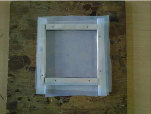
3.3.3 Composite preparation
Initially, wooden moulds with dimensions of 140 x 120 × 10 mm3 were prepared for the fabrication. For different number a layer of fibre, epoxy resin and hardener (ratio of 10:1 by weight) with a calculated amount was mixed thoroughly in a glass jar. Figure 3.1(a) illustrates the mould used to construct the composite. Mould release sheet was put over the glass plate and a mould release spray was sprayed over the inner surface of the mould for quick and easy removal of composite. After keeping the mould on a ply board a thin layer of the mixture was poured. Then the fiber lamina was distributed on the mixture. Then again resin was applied over the fiber laminate and the procedure was repeated to get the desired thickness. The remaining mixture was then poured into the mould. Precaution was taken to prevent the air bubbles formation. Then from the top pressure was applied and the mould was kept at room temperature for 72 hrs. During application of pressure some amount of mixture
NIT ROURKELA Page 27 of epoxy and hardener squeezes out. Care has been taken to consider this loss during manufacturing of composite sheets. After 72 hrs the samples were taken out of the mould. Figure 3.2 (a, b) shows the photograph of the composite specimen cut for further experimentation.
Figure- 3.1 Mould used for fabrication of the composite
NIT ROURKELA Page 28 Figure-3.2 (b) Tensile test samples
3.4. STUDY OF ENVIRONMENTAL EFFECT
To study the effect of environmental conditions on performance of Luffa Cylindrica fiber epoxy composite, the composite sample with both untreated and chemically treated fibers were subjected to various environments such as:
(a) Saline treatment (b) Distil treatment
3.4.1 Moisture absorption test
Moisture absorption and thickness swelling tests were conducted in accordance with ASTM D570-98. Four specimens for different layers (Single, Double and Triple layers) were cut with dimensions of 140 x 15mm (length x width) and the experiment was performed using test samples. The specimens prior to testing were dried in an oven at 800 C and then were allowed to cool to room temperature and kept in a desiccator. The weight of the samples were taken before subjected to steam, saline water and distil water environments. After expose for 12 hr, the specimens were taken out from the moist environment and all surface moisture was removed with a clean dry cloth or tissue paper. The specimens were reweighed to the nearest 0.001 mg within 1 min. of removing them from the environment chamber. The specimens were weighed regularly from 12-156 hrs with a gap of 12hrs of exposure. The moisture absorption was calculated by the weight difference. The percentage weight gain of the samples was measured at different time intervals by using the following equation:
NIT ROURKELA Page 29
0 0 t t W 100 W W %M (3.1) Where ‘W0’ and ‘Wt’ denote the oven-dry weight and weight after time ‘t’, respectively.Equilibrium Moisture Content (EMC) of the sample is the moisture content when the periodic weight change of the sample was less than 0.1% and thus the equilibrium state was assumed to be reached.
The thickness swelling (TS) was determined by using the following equation:
100 H H H TS(t) 0 0 t (3.2)
Where, ‘Ht’ and ‘H0’ are the composite thickness after and before the water immersion
respectively.
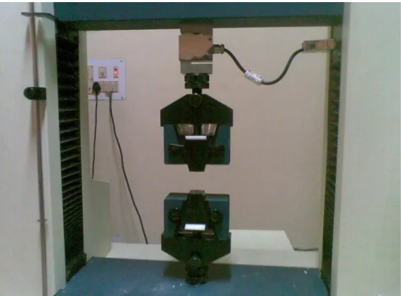
3.4.2 Mechanical testing of sample 3.4.2.1 Tensile test
The tensile test is generally performed on flat specimens. The most commonly used specimen geometries are dog-bone and the straight side type with end tabs. The specimen used in present case is shown in fig 3.3 (a). The tensile tests were conducted according to ASTM D 3039-76 standard on a computerized Universal Testing Machine INSTRON H10KS. The span length of the specimen was 42 mm. the tests were performed with constant strain rate of 2 mm/min.
NIT ROURKELA Page 30 Figure-3.4 (a) UTM machine sample unloaded for tensile testing
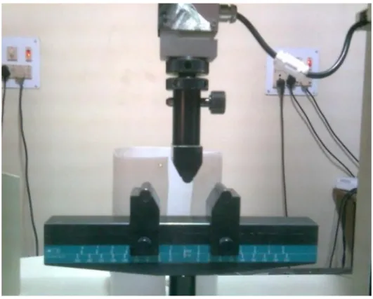
NIT ROURKELA Page 31 3.4.2.2 Flexural test
Three point bend test was carried out in an UTM machine in accordance with
ASTM D790-03 to measure the flexural strength of the composites. The loading arrangement for the specimen and the photograph of the machine used are shown in figure 3.5. All the specimens (composites) were of rectangular shape having length varied from 100-125 mm, breadth of 100-110 mm and thickness of 4-8 mm. A span of 70 mm was employed maintaining a cross head speed of 0.5mm/min.
The flexural strength of composites was found out using the following equation
τ =
Where τ is the flexural strength, f is the load, l is the gauge length, b is the width and t
is the thickness of the specimen under test.
NIT ROURKELA Page 32
3.4.3 Results and discussion
3.4.3.1 Moisture absorption behaviour
The results of both untreated and treated fibre composite samples exposed to different environments are shown in Table-3.1 to 3.24.
Figure-3.22 to 3.29 shows the percentage of moisture absorption characteristics of composite samples with untreated and treated fiber exposed to Saline water and Distil environment with time. It is quite obvious from the figure that as the fibre content increases, the initial rate of moisture absorption and the maximum moisture absorption for both the environment increases. Moisture absorption is maximum for three layered composites. It is known that, the factors like adhesion between fibre and matrix, porosity content and the lumen are responsible for the moisture absorption behaviour of the natural fibre composites. But in this case the hydrophilicity of Luffa Cylindrica fiber, in addition to poor adhesion between fiber–matrix and voids content might have affect the moisture uptake characteristics of the composite.
Again it is observed that, the moisture absorption increases as the immersion time increases, and got saturated after certain time period. Time required to reach the saturation point is not same for both the environments. The saturation time is approximately 120 hrs for distil, and 108 hrs for saline water. Environmental conditions also play a significant role in moisture absorption process. Figure-3.30 to 3.33 shows the maximum moisture absorption of composite in all three environments. In Distil Water environment moisture absorption is maximum as compare to saline water environment. The rate of absorption in case of saline water is low as compared to steam. This happens because of the gathering of NaCl ions in the fibre’s surface immersed in saline water, which increases with time and delays moisture diffusion [122].
Figure-3.22 to 3.29 shows that the moisture absorption behaviour of the chemically treated fibre reinforced epoxy composites was lesser than that of the untreated fibre when exposed to different environmental treatment. It is clear from these plots that the change in surface chemistry of the fibre reduces the attraction of fibers to moisture. Due to surface modification by chemical treatment, the fibers get covered with the epoxy resin with a stronger adhesion, resulting in less moisture uptake.
NIT ROURKELA Page 33 3.4.3.2 Measurement of Diffusivity
The water sorption kinetics in LCF reinforced epoxy composite has been studied
through the diffusion constants k and n. The behaviour of moisture sorption in the composite
was studied by the shape of the curve represented by the equation (3.3) [37, 38]:
ktn m M t M (3.3)
Where, Mt is the moisture content at specific time‘t’,
Mm is the equilibrium moisture content (EMC), and
k and n are constants.
The value of k and n were found out from the slope and the intercept of Mt /Mm
versus time ‘t’ in the log plot which was drawn from the data obtained from experiment of moisture absorption with time.Figure-3.14 to 3.16 and Figure-3.17 to 3.19 showed the typical curve of log (Mt/Mm) as a function of log (t) for both untreated and treated LCF reinforced
epoxy composite respectively, used to determine these constants.