A cc ele ra tio n o f P ed es tr ia n D et ec tio n S ys te m u sin g H ar dw ar e -S o ft w ar e C o -d es ign
Department of Electrical and Information Technology, Faculty of Engineering, LTH, Lund University, March 2015.
Acceleration of Pedestrian
Detection System using
Hardware-Software Co-design
Mao Hatto
M ao Hat toMaster’s Thesis
Series of Master’s theses
Department of Electrical and Information Technology LU/LTH-EIT 2015-436
Acceleration of Pedestrian Detection System using
Hardware-Software Co-design
Mao Hatto
Department of Electrical and Information Technology
Lund University
Advisor: Hideharu Amano
March 25, 2015
Printed in Sweden E-huset, Lund, 2015
Abstract
Object detection technologies, represented by face detection system which has been stud-ied for a long time, have developed recently because of the development of technologies of high performance computing and pattern recognition technique. Especially, pedestrian detection system has gathered attention recently, and it will be applied to an automobile safety system and monitoring camera system.
While many research of acceleration and improvement of detecting accuracy have been published, system design as distributed system is also required. While a central-ized computing system which sends raw image data to central processing node presses networks, distributed system which operates some calculation before sending data to the network decreases the total amount of data volume.
When we take account of using environment of pedestrian detection system, user flexibility is also important criteria. Pedestrian detection system should be set some pa-rameters such as detecting window size, slide width of window and operating speed de-pending on each using environment. When you implement the whole system on an FPGA, you will lose flexibility of the system. Hardware-Software Co-design enables to enhance flexibility.
Thinking of demands mentioned in above, this thesis aims acceleration of pedestrian detection system using Hardware-Software Co-design. In the implementation, our sys-tem adopts HOG (Histogram of Oriented Gradients) feature value and Real Adaboost as a classification algorithm. Also, our system aim data reduction without decrease of detecting accuracy, design as distributed system by implement on a single FPGA, and enhancement of flexibility using Hardware-Software Co-design.
HOG feature data is reduced by segmenting to 6bit after converting HOG feature value from floating-point number to fixed-point number. In addition, output of classifier by Real Adaboost algorithm is calculated by high-precision in advance, and these values are stored to ROM on the FPGA. This enables to reduce data volume without much loss of detecting accuracy.
As a result, whole pedestrian detection system is implemented on a single FPGA board, and it accelerated in 3.22 faster than software only operation. In addition, feature data is reduced by 93.5% without much loss of detecting accuracy. Enhancement of flexibility using Hardware-Software Co-design also accomplished with ZedBoard FPGA and ARM Coretex-A9 processor on the board.
Table of Contents
1 Introduction 1
1.1 Background . . . 1
1.2 Objectives . . . 2
1.3 Structure of the thesis. . . 3
2 Pedestrian Detection System 5 2.1 System Algorithm . . . 5
2.2 Feature Extraction. . . 6
2.3 Recognition and Classification . . . 8
3 Related Works 11 3.1 Related Work 1 . . . 11
3.2 Related Work 2 . . . 11
3.3 Related Work 3 . . . 12
3.4 Other Related Works and Discussion . . . 14
4 Design and Implementation 17 4.1 Implement Environment and FPGA Board. . . 17
4.2 Algorithm Optimization . . . 19 4.3 System Profiling . . . 20 4.4 Hardware-Software Co-design . . . 21 4.5 Data Reduction . . . 22 4.6 Architecture . . . 24 5 Evaluation 29 5.1 Resource Utilization . . . 29 5.2 Execution Speed . . . 29 5.3 Data Volume . . . 31 5.4 Detecting Accuracy . . . 32 6 Conclusion 35 References 37
iii
A AXI Bus Signal 39
B Xilinx IP Core Generator 43
C Camera Module 45
List of Figures
1.1 System overview . . . 2
2.1 Cell, Block and histogram in HOG Feature Extraction . . . 7
3.1 Centralized and Distributed System . . . 14
4.1 ZedBoard . . . 18
4.2 Zynq Overview. . . 19
4.3 Algorithm Optimization . . . 20
4.4 Window-based Scanning and Cell-based Scanning . . . 21
4.5 Hardware-Software Co-design . . . 23
4.6 Data reduction method . . . 24
4.7 Whole Architecture . . . 25
4.8 Block Diagram ofGradient ComputationCore . . . 26
4.9 Block Diagram ofNormalizationCore . . . 26
4.10 Block Diagram ofReal AdaboostCore . . . 27
5.1 Resource Utilization . . . 31
5.2 DET curve of the system . . . 33
5.3 Test Sample Example . . . 34
A.1 Reading transaction . . . 39
A.2 Writing transaction . . . 40
A.3 Data transaction of AXI4-Stream . . . 41
C.1 MT9D111 Camera Module . . . 45
List of Tables
3.1 Summary of Related Work 1 . . . 12
3.2 Summary of Related Work 2 . . . 13
3.3 Classification rate and memory size for processing an image . . . 13
4.1 Result of Profiling . . . 22
5.1 Resource Utilization . . . 29
5.2 Resource Utilization (Detail) . . . 30
5.3 Operating Speed . . . 30
5.4 Data volume comparison . . . 31
5.5 Comparison of error rate of miss detection . . . 34
C.1 Pin List of MT9D111 Camera Module . . . 46
C.2 Key Performance Parameters (excerpt) . . . 46
Chapter
1
Introduction
1.1
Background
As technologies of high performance computing and pattern recognition have developed rapidly, a pedestrian detection system has also gathered attention recently. Pedestrian de-tection system can be applied for many objectives, such as an automobile safety system, an automatic traffic census system and a crime prevention system. Especially in the moni-toring camera system, collected feature data are expected to be stored in data base servers, and used for big data analysis. Also from the viewpoint of privacy protection, not using picture data but using secondary data, such as detecting result or feature data, is desirable. Although various kind of methods for extracting feature data for pedestrian detec-tion system are proposed, HOG (Histogram of Oriented Gradients)[1] proposed N.Dalal and B.Triggs has been an effective way for extracting feature values. Also, Adaboost algorithm[2] proposed by R.E. Schapire and Y.Singer has high recognition ratio and is easy for hardware implementation. Furthermore, Real Adaboost[3], an improved algo-rithm of adaboost, extends output values of weak classifier from a binary number to a real number.
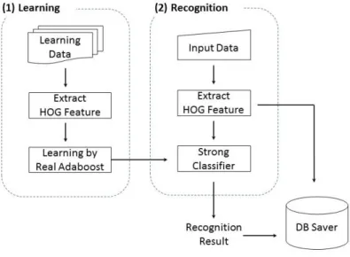
Figure 1.1 shows the overview of a pedestrian detection system. It can be divided into two phases: learning phase and recognition phase. The learning phase extracts HOG feature values from prepared learning positive and negative data, and performs learning using Real Adaboost algorithm. This phase generates strong classifier, and it is used in the recognition phase. In the recognition phase, extracting HOG feature values from input data are judged whether the input data include pedestrian or not. If the system detects pedestrian in the picture, extracted HOG values are sent to the database server.
A lot of researches on pedestrian detection systems adopted these two algorithms, and achieved a certain progress. However, data volume of HOG feature is still a problem of the whole system. Much data volume consumes much block RAM in an FPGA, and it makes difficult to implement on a single FPGA. Also it increases communication time between each block in FPGA. Although one of the related work proposed feature data reduction using binary pattern for HOG feature values[4], it also causes deterioration of recognizing accuracy. As performance of detection is the most important evaluation criteria, it should be kept even data values are reduced.
2 Introduction
Figure 1.1:System overview
1.2
Objectives
Based on the section above, there are three criteria in pedestrian detection system: detec-tion accuracy, detecdetec-tion speed and data volume. Detecdetec-tion accuracy could be improved by algorithmic way or increasing learning times in the learning phase. As detection speed and data volume could be improved via hardware design, this thesis especially focuses on these two points.
In addition, two proposals will be shown in this thesis. One is necessity of Hardware-Software co-design. Though pedestrian detection system is supposed to be used in various situation, specific parameters related to detecting speed, detecting window size or slide width of detecting window should be able to be changed easily by users. Hardware-Software co-design enables this and it enhances flexibility.
Another proposal is design as a distributed processing system. Pedestrian detection system such as an automatic traffic census system and a crime prevention system have many camera modules, and they communicate with host machine. If raw image data are sent in order to all operations are processed in the host machine, an enormous amount of packets are generated in the network. This causes the overall speed reduction and oppressing network resources.
Therefore, this thesis objects three point mentioned below.
• Implement whole pedestrian detection system, from input from camera module to output to a display.
• Aim to acceleration and data reduction without deterioration of recognizing accu-racy.
Introduction 3
• Implement whole system into a single FPGA in order to design as a distributed processing system.
1.3
Structure of the thesis
This thesis is organized as follow. Chapter 2 gives an overview of pedestrian detection system and detail of HOG feature extraction and Real Adaboost, then Chapter 3 mentions some related works and their achievement. Chapter 4 explains implementation of FPGA, and Chapter 5 shows the result of evaluation. Finally, Chapter 6 concludes the thesis.
Chapter
2
Pedestrian Detection System
This section gives an overview of the pedestrian detection system, and explains algorithms used there. While whole system overview of pedestrian system has been shown in Figure 1.1, this chapter explains detailed algorithm. In addition, HOG feature extraction and Real Adaboost learning and detecting algorithm are explained with some equations.
2.1
System Algorithm
Listing 2.1 shows the C-like pseudo code of pedestrian detection system. First of all, input_image()sub routine inputs image data from camera module. Next,Gray_scaling() converts input image into gray scale image, andInitialization()routine allocates memory and initializes them. Then, detecting window is extracted by Raster Scan inforstatement. This process is iterated depending on the number of extracted window. In each iteration, feature extraction by HOG algorithm and recognition using Real Adaboost are the main part and these two parts consumes most of the operated time. HOG algorithm consists of three sub routines:Gradient_computation(),Orientation_binning()andNormalization(). After extracting HOG feature values, RealAdaboost()sub routine judges if the window includes pedestrian or not using Real Adaboost detecting algorithm. If the judgment is true, information of the window and detecting result are stored byVoting()sub routine.
Since some windows are determined to be true for one detection point, it is necessary to integrate them into a single window.Mean_Shift()andNearest_Neighbor()subroutines play a part of it. Then finallyOutput_Image()outputs the image with detected window to a display.
6 Pedestrian Detection System
Listing 2.1:Pseudo Code of Pedestrian Detection System
1 intmain() 2 { 3 Input_Image(); 4 gray_scaling(); 5 initialization(); 6
7 for(Raster Scan){
8 //Extract HOG feature values
9 Gradient_computation(); 10 Orientation_binning(); 11 Normalization(); 12
13 //Detecting by Real Adaboost
14 if(RealAdaboost()==true){ 15 Voting(); 16 } 17 } 18 //Window merging 19 Mean_Shift(); 20 Nearest_Neighbor(); 21 22 Output_Image(); 23 }
2.2
Feature Extraction
Although various feature extraction methods were proposed, HOG (Histogram of Ori-ented Gradients) has been the most popularly used method in object detection systems.
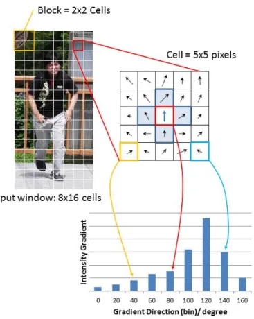
In HOG feature extraction, input window is divided into some cells, which are com-posed by a certain number of pixels. Gradients histograms are generated in each cell, and they are normalized in each block, which contains some cells. Figure 2.1 shows win-dow, cell, block and extracted histogram in each cell in HOG feature extraction algorithm. More details of HOG algorithm is shown below.
2.2.1
Gradient Computation
The first step of calculation is computing Intensity derivative fx,fyby intensityL(x,y) in
each pixel. Then, intensity gradientsm(x,y) and intensity gradientθ(x,y) are computed. fx(x,y)=L(x+1,y)−L(x−1,y) fy(x,y)=L(x,y+1)−L(x,y−1) (2.1) m(x,y)= √ fx(x,y)2+fy(x,y)2 (2.2) θ(x,y)=tan−1fy(x,y) fx(x,y) (2.3)
Pedestrian Detection System 7
Figure 2.1:Cell, Block and histogram in HOG Feature Extraction
2.2.2
Orientation Binning
The next step is making histograms in each cell. Calculatebinfor binning by intensity gradientsθ(x,y) and azimuthal quantum numberN.
bin=Round(θ(x,y)+π 2)× 180 π × N 180 (2.4)
2.2.3
Block Normalization
Finally, feature valuesvare normalized in each block. vn= v v t ( k ∑ i=0 v(i))2+ϵ (2.5)
8 Pedestrian Detection System
2.3
Recognition and Classification
Adaboost, a machine learning algorithm proposed by Y.Freund and R.Schapire, has high degree of detective ratio and is easy to be implemented. While Adaboost algorithm uses weak classifier with binary {+1, -1} outputs, Real Adaboost, an improved version of Adaboost, uses weak classifier with real number outputs. Compared with Adaboost, Real Adaboost has high recognition ratio with fewer classifiers in general.
We can divided Real Adaboost algorithm into two phase: learning and classification. Specification of each Real Adaboost phase is shown below.
2.3.1
Learning
As a precondition, N learning sample data (xi,yi),(i = 1, ...,N) and weighting number
Dt(i) are prepared. xi means input sample data and yi+1,−1 shows class label which
shows whether any person appears in the sample data or not. Diis initialized 1/Nat the
beginning of the learning phase.
After initialization, the following tasks for number of learning t = 1,2, ...,T and number of weak classifiersm=1,2, ...,Mare operated.
The first step of learning generates candidates for probability density distributions. By feature values of learning samplexiand quantifying number j, two probability density
distributionsW+jandW−jare generated.
W+j = ∑ i:j∈yi=+1 Dt(i) W−j = ∑ i:j∈yi=−1 Dt(i) (2.6)
Next step is estimating weak classifier by evaluation value Zm and calculating the
value of weak classifier by (2.8).
Zm=1−2 ∑ j √ W+jW−j (2.7) h(x)=1 2ln W+j+ϵ W−j+ϵ (2.8) Then, updating weighting numberDt(i) by equation (2.9) and (2.10).
ht=minZt,m (2.9)
Dt+1(i)=Dt(i)exp[−yiht(xi)] (2.10)
2.3.2
Classification
Pedestrian Detection System 9
1. Quantize input feature valuexby
j= f loor(x×64) (2.11) 2. LoadingW+jandW−j 3. Calculatingh(x) h(x)=1 2ln W+j+ϵ W−j+ϵ (2.12)
4. Summing uph(x) of every inputx. H(x)=
∑
t
ht(x) (2.13)
Chapter
3
Related Works
This section shows some related works, and reveal the achievement and challenges. First related work designed multi-FPGA system for HOG feature extraction and Real Ad-aboost. Second related work implemented on pedestrian detection system by Binary pat-tern HOG and Adaboost on a single FPGA. Third related work focused on data reduction method for HOG extraction algorithm. After introducing these three related works, we discuss their contribution and other works.
3.1
Related Work 1
“An Image Recognition System for Multiple Video Inputs over a
Multi-FPGA System”
T.Otsuka, et al.[5], designed multi-FPGA system for image recognition system using HOG feature and Real Adaboost classification. Their platform device named Cloud of Reconfigurable Device (CoRD) contains of a controller PC and FPGA printed circuit boards (PCBs) connected to each other with a high-speed serial interface. Each PCB has a Gateway FPGA and some tile FPGAs, and they are connected by local bus. The gateway FPGA has memory controllers handling DDR3 SDRAM for the video frame buffer.
As a result, they achieved operating speed in 30 fps with 720 x 480 pixels per frame. They also contributed to improve flexibility by HW/SW communication interface. Sum-mary of this paper is shown in Table 3.1.
3.2
Related Work 2
“Deep pipelined one-chip FPGA implementation of a real-time
image-based human detection algorithm[6]”
12 Related Works
Table 3.1:Summary of Related Work 1
Platform
Multi FPGA system
Input image size
720 x 480 pixels
Number of window per frame
35,000
Algorithm
HOG
+
Real Adaboost
Gateway-FPGA
Slice: 18,479
/
37,680 (49%)
Resource
Block RAM (36KB): 245
/
416 (58%)
Tile-FPGA
Slice: 11,737
/
37,680 (31%)
Block RAM (36KB): 248
/
416 (59%)
Max frequency
27 MHz
Throughput
30 fps
Detection rate
no data
False positive rate
no data
This paper tried to implement pedestrian detection algorithm using HOG and Ad-aboost classification on a single FPGA (Virtex-5 VLX-50). In order to implement on a single FPGA without any external memory modules, they tried to use binary patterned HOG and some approximation arithmetic strategies. Their system achieved 62.5 fps of the throughput, showing 96.6% and 20.7% of the detection rate and the false positive rate, respectively.
The most important contribution of this paper is to present an implementation of HOG feature extraction and Adaboost classification on a single FPGA without external memory. Table 3.2 shows the summary of this related work.
3.3
Related Work 3
“A method for reducing number of HOG features based on Real Adaboost[4]”
C.Matsushima et al. tried to data reduction of HOG features[4]. They proposed binarized HOG features on pedestrian detection system using HOG and Real Adaboost, which are the same algorithm used in this thesis.
Related Works 13
Table 3.2:Summary of Related Work 2
FPGA
Xilinx Virtex-5 VLX-50 (ML501)
Input image size
320 x 240 pixels
# of window per frame
1540
Algorithm
Binary pattern HOG
+
Adaboost
Number of Slice Registers: 2,181
/
28,800 (7.6%)
Resource
Number of Slice LUTs: 17,383
/
28,800 (60.4%)
Number of Block RAM: 36
/
48 (75.0%)
Max frequency
44.85
Throughput
62.5 fps
Detection rate
96.6%
False positive rate
20.7%
andbdmean HOG feature and binarized HOG feature respectively, andthmeans threshold
value which is set in 0.03 in this proposal.
bd=
1 vd ≥th
0 otherwise (3.1)
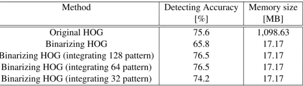
Although converting the HOG feature to binary pattern enables to reduce the to-tal amount of memory space, it also causes the problem of a sparse probability density distribution used in classification. While this method declines detection accuracy about 10%, they proposed additional method which integrates the binary pattern during training phase.
As the result, while single binarizing HOG feature declines detection accuracy in 9.8%, they achieved data reduction with keeping detection accuracy as same level as conventional way by integrating binary pattern. This result shows in Table 3.3.
Table 3.3: Classification rate and memory size for processing an
image
Method
Detecting Accuracy
Memory size
[%]
[MB]
Original HOG
75.6
1,098.63
Binarizing HOG
65.8
17.17
Binarizing HOG (integrating 128 pattern)
76.5
17.17
Binarizing HOG (integrating 64 pattern)
76.5
17.17
Binarizing HOG (integrating 32 pattern)
74.2
17.17
14 Related Works
3.4
Other Related Works and Discussion
First related work[5] shows the implementation on multi-FPGA system. Other woks im-plement pedestrian detection system on high-performance computing (HPC) systems. R.Benenson, et al.[7] achieved 135 fps using CPU+GPU desktop machine. S.Bauer, et al.[8] designed FPGA-GPU architecture for pedestrian detection using HOG and SVM (Support Vector Machine), and achieved 10 fps for 800 x 600 pixels input, and 1,000 detecting windows are extracted in a frame.
Such related works on HPC system achieved to design pedestrian detection system in high speed, and their system are supposed to be used as centralized computing system. Although they contributed design of a high-performance system and improved flexibility since some of the system includes software operation, such a centralized computing sys-tem increases network traffic. In Figure 3.1 compares centralized systems and distributed systems. In centralized systems, central system processes all data from each node, and data traffic of network is increased since each node sends raw pixel data in each frame. On the other hand, distributed system showed in Figure 3.1.b has FPGA board in each node, and they processes detecting result data before sending data to network. Although each node is more complex than centralized system, network traffic is much smaller.
Figure 3.1:Centralized and Distributed System
Second related work[6] implemented on one-chip FPGA as each node of distributed system. In order to implement on a single FPGA, they proposed binary pattern HOG algorithm. Although this algorithm enables us to reduce memory space on FPGA board,
Related Works 15
it decreases detecting accuracy. Third related work[4] tried to solve it, and proposed improved method for binary pattern HOG. Although distributed pedestrian detection sys-tems are designed in these two works[6][4], they decrease flexibility of the syssys-tems since they implemented whole system on a single FPGA.
In this thesis, we aim pedestrian system designed as distributed system with high flexibility by Hardware-Software Co-design.
Chapter
4
Design and Implementation
This chapter explains design and implementation. Section 4.1 shows implement envi-ronment, especially FPGA and camera module. ZedBoard has AXI bus as an on-chip interconnect protocol between software core and programmable logic. This chapter also explains detail of AXI protocol. Section 4.2 reviews system algorithm and discusses op-timization of it for the purpose of Hardware-Software Co-design. Section 4.3 gives the result of system profiling, and examines which part of the program consumes most of the execution time. Section 4.4 shows Hardware-Software Co-design based on algorithm op-timization and profiling result. Section 4.5 discusses data size of HOG feature values, and examines data reduction method. Finally, Section 4.6 explains detail of the architecture.
4.1
Implement Environment and FPGA Board
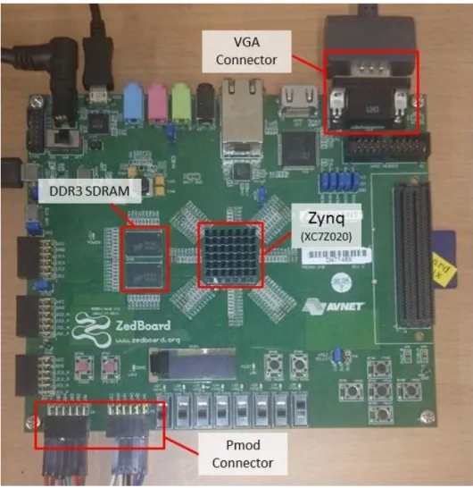
This thesis adopts ZedBoard[9], which is designed board for the Xilinx Zynq-7000 All Programmable SoC[10], as a target FPGA, and Xilinx tools as a development environ-ment. Figure 4.1 shows ZedBoard and their connections, and key features of ZedBoard are listed below.
• Zynq-7000 All Programmable Soc XC7Z020-CLG484-1 • 512 MB DDR3 memory
• Pmod headers (2x6) expansion • VGA connector
• On-board USB JTAG programming port
18 Design and Implementation
Figure 4.1:ZedBoard
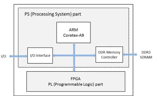
Overview of Zynq device is shown in Figure 4.2. Zynq consists of two pars: Pro-cessing System (PS)andProgrammable Logic (PL). PS has ARM-Coretex A9 Processor which operates in 866 MHz at the maximum, memory controller and I/O interface. PL operates as FPGA, and it is able to communicate with ARM processor via AXI bus. Detail of AXI bus signal is explained in Appendix A.
ZedBoard also has DDR3 SDRAM memory next to Zynq device. In our design, ZedBoard inputs image data from through Pmod connector, and outputs image to VGA display through VGA connector.
Our system adopts MT9D111 CMOS Camera module as input device. The camera module sends 800 x 600 pixels in 30 fps. More specification of the camera module is mentioned in Appendix C.
Design and Implementation 19
Figure 4.2:Zynq Overview
4.2
Algorithm Optimization
This section discuss optimization of whole system algorithm for Hardware-Software Co-design execution.
4.2.1
Cell-based scanning
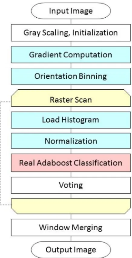
Figure 4.3.a shows flowchart of original algorithm. HOG extraction, showed in blue in Figure 4.3, is divided in three parts; gradient computation, orientation binning and normalization. Since this process is iterated in each detection window, it consumes much execution time.
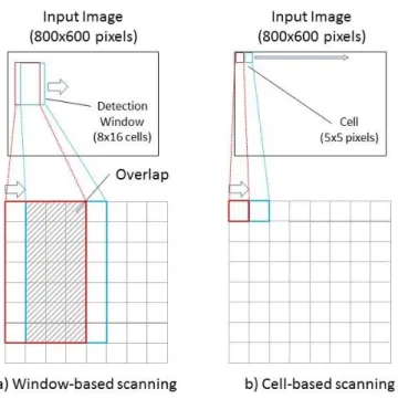
In original HOG algorithm[1], as each HOG feature extraction is operated after scanned each detection window and the detection window is slided in some pixels in this case, there are many overlaps as shown in Figure 4.4.a. If you have 8x16 cells in a window and slide in one cell each, you will get 7x15=105 cells overlap. This overlap means increasing data traffic of pixel values and leads low fps in whole system.
Cell-based scanning method is an optimized algorithm for HOG feature extraction by K.Mizuno et, al.[11]. Figure 4.4.b shows the concept of Cell-based scanning which avoids pixel overlap. Cell-based scanning method computes all gradient values before determination of detecting window by Raster Scan, showed in Figure 4.3.b. Gradient Computation andOrientation Binning is executed before Raster Scanloop, and Load Histogramwhich accesses memory and load each histogram data in the detecting window, is added inside the loop. Although cell-based scanning method adds Load Histogram procedure, it decreases much workload. In the proposed paper[11], HOG algorithm with
20 Design and Implementation
cell-based scanning and SVM calculation reduces the workload from 447.7 GOPs to 10.6 GOPs.
[a] Original Algorithm
[b] Modified Algorithm with Cell-based
Scanning
Figure 4.3:Algorithm Optimization
4.3
System Profiling
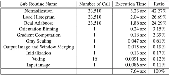
Based on optimized algorithm mentioned in Section 4.2.b, we profiled whole system using only ARM Coretex-A9 processor on ZedBoard. Sub routine name is corresponding to Figure 4.3.b.
From the result of profiling,Normalizationsub routine occupies most of the percent-age of execution time, and we can expected that hardware implementation of this routines decrease total execution time. Load Histogramoccupies the second largest percentage, however, most of this routines are memory accessing operation. Therefore, we assessed that it is unsuited for hardware implementation. Orientation Binningis also unsuited for hardware implementation for the same reason. As a result, we tried to implement on
Design and Implementation 21
Figure 4.4:Window-based Scanning and Cell-based Scanning
hardware three subroutines:Normalization,Real AdaboostandGradient Computation.
4.4
Hardware-Software Co-design
Based on the idea of Cell-based scanning method mentioned in Section 4.2 and the re-sult of profile showed in Section 4.3, we designed Hardware-Software Co-design of the Pedestrian Detection System (Figure 4.5).
Three accelerated modules,Gradient Computation,NormalizationandReal Adaboost core, and camera interface and VGA controller core are located on Programmable logic of FPGA. Other process are executed by ARM Coretex-A9 processor, and they commu-nicate data each other via AXI bus.
AsRaster ScanandLoad Histogramoperate in software side, we can adjust detecting window size, number of detecting window depends on the usage environment, and it increases the flexibility of the system.
4.4.1
System Flexibility
Hardware-Software Co-design allow us not only to implement on a single board, but also to enhance system flexibility. While we need to redo implementation when we want to change some parameters in the system in Hardware only implementaion, our system
22 Design and Implementation
Table 4.1:Result of Profiling
Sub Routine Name
Number of Call
Execution Time
Ratio
Normalization
23,510
3.23 sec
42.27%
Load Histogram
23,510
2.04 sec
26.69%
Real Adaboost
23,510
1.86 sec
24.29%
Orientation Binning
1
0.24 sec
3.15%
Gradient Computation
1
0.18 sec
2.39%
Gray Scaling
1
0.047 sec
0.61%
Output Image and Window Merging
1
0.015 sec
0.19%
Initialization
1
0.13 sec
0.17%
Voting
16
0.0091 sec
0.12%
Input image
1
0.0086 sec
0.11%
7.64 sec
100%
enables us to adjust some parameters easily. The parameters which we can adjust are listed below.
• Size of detecting window
• Shifting width of detecting window
• Threshold value in Real Adaboost classification
Depending on a distance between camera module and pedestrians, size of detecting window should be modified. Also, shifting width of detecting window should be changed depending of the demanding operating speed. If you would increase the shifting width of detecting window, the system is accelerated while detecting accuracy may be decreased as the total number of detecting window is decreased. Furthermore, we can adjust miss rate and false positives per window of the system by changing threshold value in Real Adaboost classification.
4.5
Data Reduction
4.5.1
Data Size of Original Algorithm
HOG feature hasNfeature values in each cell (Nrepresents an azimuthal quantum num-ber in equation (2.4)), and also these feature values are normalized in shifted block. If we assume that one window has 8x16 cells, one block composed by 2x2 cells and azimuthal quantum number is 9, there are 3780 (7x15x2x2x9) feature data generated in total. In software execution, HOG feature values are calculated in double precision (8 byte), thus, total data volume per window becomes 30.24K Byte.
As detection window slides and also window size is scaled in the recognition phase, total occupied memory space is increased. If we assume that scanning 50,000 windows per one input image, total amount of memory space exceeds 1.5 GB. Using such a huge
Design and Implementation 23
Figure 4.5:Hardware-Software Co-design
memory space in an FPGA, we need external memory like DDR3 SDRAM. It means communication with DDR3 and programmable logic might be a bottleneck of execution speed. Also from the view of saving feature data to a data server, too much data volume increases its running cost.
As we showed in Section 3, data reduction method from 64 bit to 1 bit using binarized HOG[4] had been proposed. Although this proposal reduced feature data volume much, detection accuracy is also decreased. If they kept detection accuracy as same level as conventional way by introducing binary pattern and binary selection algorithm, occupied resource and latency in the FPGA are increased.
In this thesis, we propose an approach that is using fixed point calculation to reduce feature data volume without large additional resource and complex coding.
4.5.2
Data Reduction Method
In the classification phase of Real Adaboost, the accuracy of weak classifier outputs has the highest effects on the output accuracy, and classifier outputs are calculated by HOG feature value (Equation (2.8)).
Considering the above, we calculated all possible outputs data of weak classifier (Equation (2.6)) in a high precision in advance, and storing them into the ROM on the FPGA. Therefore, in the FPGA, we need to access the ROM only. As the probability
24 Design and Implementation
density is distributed in a weak classifier binning in 64 (26), bit width for accessing the
ROM is 6 bits. This method can decrease HOG feature data from 64 bits to 6 bits, with the same accuracy as software execution in double precision. Figure 4.6 compares original Real Adaboost classification algorithm and ours.
Figure 4.6:Data reduction method
4.6
Architecture
Figure 4.7 shows the whole architecture in the FPGA. There are three accelerated hard-ware modules, shown by light-yellow, are mapped on Programmable Logic, and they are connected to ARM Coretex-A9 processor. AXI DMA Engines are used for converting AXI4 (Memory Mapped communication) to AXI4-Stream communication.
More specifications of these logic are mentioned below.
4.6.1
Gradient Computation
For 18 bit x 1 frame (800x600 pixels) input, 14 bit x one frame is outputted. Gradient Computationmodule, shown in Figure 4.8, operates asGradient_computation()routine in Listing 2.1. One input data composed of two Intensity derivative (fx,fy) are pushed into
a FIFO. These input data are calculated as Equation (1) to (4), then the pair of intensity gradientm(x,y) and direction of gradientbinare sent back to ARM core.
Bit width of each signal is shown in red letter, and module, which are SQRT and Arctan, which are shown in light-yellow box, are generated by Xilinx Core generator. Detail of Xilinx IP Core is explained in Appendix B.
4.6.2
Normalization
For 13 bit x 1152 inputs, 6 bit x 3780 frame are outputted. This module, showed in figure 4.9, normalizes each block in input window. One window has 8x16 cells, and each cell
Design and Implementation 25
Figure 4.7:Whole Architecture
has 9 features. Thus, there are 1152 inputs. Also, as we set 2x2 cells in one block, there are 3780 output data.
After receiving input data, nine parallelized calculation logic operates in parallel, and it enables us to accelerate the calculation.
4.6.3
Real Adaboost
Figure 4.10 shows block diagram of Real Adaboost module. This module is designed based on data reduction method which is mentioned in Section 4.5. As the only execu-tion in this module is accessing ROM data which has previous classifier calculaexecu-tion data, therefore, block diagram of this module is simple. After accessing the ROM, all of these data are summed up and compared withλ, a threshold for detection.
26 Design and Implementation
Figure 4.8:Block Diagram ofGradient ComputationCore
Design and Implementation 27
Chapter
5
Evaluation
5.1
Resource Utilization
Total resource utilization is shown in 5.1. Since usage of slice register and slice LUTs are 19% and 27% respectively, there are more space to implement additional modules.
Also, Table 5.2 shows resource utilization of each module. GPIO(General Purpose IO) outputs signals from the camera interface and VGA controller to each device, and AXI IIC (Inter-Integrated Circuit) writes option values on the registers of the camera module.
Figure 5.1 shows the usage ratio of Slice Register, Slice LUTs and Block RAM (BRAM). According to the Figure 5.1, Normalization and Adaboostmodules consume the most resources, and especially it consumes about 77% of Block RAM.
Table 5.1:Resource Utilization
Logic Utilization
Used
Available
Utilization
Number of Slice Register
20,648
106,400
19%
Number of Slice LUTs
14,821
53,200
27%
Number of Block RAM
99
420
24%
Number of bonded IOBs
30
200
15%
Number of RAMB36E1
/
FIFO36E1s
27
140
19%
Number of RAMB18E1
/
FIFO18E1s
72
280
25%
Number of DSP48E1s
13
220
5%
5.2
Execution Speed
5.2.1
Hardware Operating Speed
From the implementation report, FPGA operates in120.7 MHz.
Since Gradient Computation takes 960,600 clock cycles per frame and Normalization +Real Adaboost takes 576 clock cycles per window, it takes 15.3m seconds per frame when 1540 windows, same as [6], are supposed to be extracted in one frame.
30 Evaluation
Table 5.2:Resource Utilization (Detail)
Register
LUT
BRAM
Gradient Computation
1468
1493
2
Normalization
+
Real Adaboost
10153
5926
76
VGA Controller
323
220
2
Camera Interface
265
200
1
DMA Engine 1
1985
1435
6
DMA Engine 2
1862
1404
6
GPIO
20
23
0
AXI IIC
342
403
0
AXI Interconnect 1
656
560
0
AXI Interconnect 2
1584
1273
3
AXI Interconnect 3
112
286
0
AXI Interconnect 4
1584
1288
3
AXI Timer
210
286
0
5.2.2
Whole System Operating Speed
Whole system operating speed is shown in Table 5.3.Only Softwarerow shows operating time by only ARM Coretex-A9 processor on ZedBoard.
Gradient Computationoperates in 4.025 millisecond on our system, while operates in 19.66 millisecond on Software execution. Normalization and Real Adaboostoperates 22.27 microseconds per window, while operates in 22.27 microseconds on Software exe-cution.
In total, our whole design achieved 3.22 speedup as software execution with 1540 detecting window per frame.
Table 5.3:Operating Speed
Only Software
Our design
speed up ratio
Gradient Computation
19.66msec.
4.025 msec.
4.89
/
frame
/
frame
Normalization and
117.26 usec.
22.27 usec.
5.27
Real Adaboost
/
window
/
window
Evaluation 31
Figure 5.1:Resource Utilization
5.3
Data Volume
By using fixed point expressions, feature data are expressed by 6 bits. It means that the total compression ratio compared to the implementation using double precision floating point numbers is about 93.75%
In the proposed method, since the values of weak classifier outputs (Equation (2.8)) are calculated in advance by double precision numbers and stored in the ROM on the FPGA, the accuracy is not much changed as that of the software execution as shown in the previous section.
Table 5.4 shows that comparison between our method and related work. Binarized HOG[4] compressed HOG feature to 1/64 with accuracy deterioration of about 9.8%. In [4], they also proposed Integrating binarized HOG in order to prevent accuracy deteriora tion, however, it increases both the resource usage and the latency.
Table 5.4:Data volume comparison
HOG
Our Method
Binalized HOG[4]
Data volume
/
window[Byte]
30,240
1968
472.5
Compression ratio
-
93.5%
98.4%
Accuracy deterioration
-
2.7%
9.8%
32 Evaluation
5.4
Detecting Accuracy
For objective estimation, we refer the classifier of Real Adaboost which is purveyed by Chubu University[12]. This classifier uses 2,054 positive samples and 6,258 negative samples, and learning in 500 times.
For test sample, we use 152 positive samples and 250 negative samples from INRIA Person Dataset[13]. Each positive sample has one pedestrian and each negative sample has no pedestrian. Figure 5.3 shows test sample example of a) Detection, b) Un-detection and c) False positives.
Figure 5.2 shows Detection Error Trade-off(DET) curves of our system. DET curves plot false positives per window (FPPW) in x-axis and miss rate in y-axis. A perfect system with zero misses and false positives per window would be positioned at the origin, thus, closer to the origin means better classifier.
In Figure 5.2, testing result of original system which is operated by Software is shown by red solid line. Other dashed lines show the result of our system with adjusting bit width of output signal of Gradient Computation module.integermeans output ofGradient Com-putationis truncated to integer value.16bit fractional,8bit fractionaland4bit fractional mean output signal is rounded to each bits after the decimal point. As we can see from Figure 5.2,16bit, 8bit and 4bit fractionalapproximate to original system, whileinteger shows somewhat far from original system.
Table 5.5 shows the error rate of miss detection compared to original system. Com-pared to only Software execution (original), our system has 2.7% of error rate of detecting accuracy with 16bit fractional. We can conclude that our data reduction method has al-most same detecting accuracy with original algorithm.
Evaluation 33
34 Evaluation
Table 5.5:Comparison of error rate of miss detection
Error Rate of miss detection
integer
8.189%
4bit fractional
3.778%
8bit fractional
2.901%
16bit fractional
2.679%
Chapter
6
Conclusion
This thesis proposed an acceleration method of pedestrian detection systems using Hardware-Software Co-design on ZedBoard. Pedestrian detection system is designed using HOG feature abstraction and Real Adaboost classification algorithm with hardware paralleliza-tion and some algorithmic optimizaparalleliza-tion. As an implementaparalleliza-tion, we aim design as dis-tributed system and increase user flexibility, besides acceleration and data reduction.
To accelerate the system, we designed three accelerated hardware cores of HOG and Real Adaboost, and achieved 3.22 speed up compare to only Software implementation. Communication between ARM processor and FPGA logic is a bottleneck of speed up, and it would be removed if bandwidth of communication bath between them are increased.
Also, we tried to reduce data volume of HOG feature values by bit cutting of HOG feature and pre-calculation of classifier. This results data reduction of 93.5% without large decreasing of detecting accuracy. This data reduction enables to implement on a single FPGA, which is a part of distributed system. Distributed system decreases communication traffic between each node and central system.
In order to increase user flexibility, we implemented by Hardware-Software Co-design. Although this implementation method decreases operating speed because of com-munication delay between Hardware and Software, it enables to adjust some parameters such as number of window, detecting window size and slide width of the window.
For our future works, data compression before sending Hardware core and Software core would be accelerate the whole system. It requires fixed length compression since these data will be sent in packet, and design additional compress/decompress logic. Be-sides, other feature algorithm or classification algorithm would have better accuracy of the system. Especially, feature values via subtraction of previous frame in video stream would improve detecting accuracy.
References
[1] N.Dalal and B.Triggs. Histogram of Oriented Gradients for Human Detection.IEEE Computer Vision and Pattern Recognition, vol.1, pp.886-893, 2005.
[2] Yoav Freund and Robert E. Schapire. A Decision-Theoretic Generalization of On-Line Learning and an Application to Boosting. Journal of Computer and System Sciences, No. 55, pp. 119–139, 1997.
[3] Robert E. Schapire and Yoram Singer. Improved Boosting Algorithm Using Confidence-rated Predictions.Machine Learning, No. 37, pp. 297–336, 1999. [4] Chika Matsushima, Yuji Yamauchi, Takayoshi Yamashita, and Hironobu Jujiyoshi.
A Method for Reducing number of HOG Features based on Real AdaBoost. In-formation Processing Society of Japan SIG Technical Report, CVIM167, 167-32, 2009.
[5] Takuya Otsuka, Takashi Aoki, Eiichi Hosoya, and Akira Onozawa. An Image Recognition System for Multiple Video Inputs over a Multi-FPGA System. IEEE 6th International Symposium on Embedded Multicore SoCs, 2012.
[6] Kazuhiro Negi, Keisuke Dohi, Yuichiro Shibata, and Kiyoshi Oguri. Deep pipelined one-chip FPGA implementation of a real-time image-based human detection algo-rithm.International Conference on Field-Programmable Technology (FPT), 2011. [7] Rodrigo Benenson, Markus Mathias, Radu Timofte, and Luc Van Gool. Pedestrian
detection at 100 frames per second. IEEE Conference on Computer Vision and Pattern Recognition (CVPR), pp. 2903–2910, 2012.
[8] Sebastian Bauer, Sebastian Kohler, Konrad Doll, and Ulrich Brunsmann. FPGA-GPU Architecture for Kernel SVM Pedestrian Detection. Computer Vision and Pattern Recognition Workshop (CVPRW), 2010.
[9] Inc. Avnet. Avnet product brief, zedboard. http://www.em.avnet.com/en-us/
design/drc/Documents/Xilinx/PB-AES-Z7EV-7Z020-G-v7-web.pdf.
[10] Inc. Xilinx. Zynq-7000 All Programmable SoC Overview (DS190, v1.7), 2014. [11] Kosuke Mizuno, Yosuke Terachi, Kenta Takagi, Shintaro Izumi, Hiroshi
Kawaguchi, and Masahiko Yoshimoto. Architectural Study of HOG Feature Ex-traction Processor for Real-Time Object Detection.2012 IEEE Workshop on Signal Processing System, pp.197-202, 2012.
38 References
[12] Dept. of Robotics Science and Chubu University Technology. Object Detection by Joint Feature Based on Relations of Local Features. http://www.vision.cs.
chubu.ac.jp/jointhog/.
[13] N.Dalal and B.Triggs. INRIA Person Dataset. http://pascal.inrialpes.fr/
data/human/.
[14] ARM. Amba axi protocol v1.0 specification. http://www.arm.com/products/
system-ip/amba/amba-open-specifications.php.
[15] J.E.Volder. The CORDIC Trigonometric Computing Technique. IRE Trans. Elec-tron. Comput. EC-8:330-334, 1959.
[16] Inc. Xilinx. Logicore ip cordic v4.0 product specification, 2011.
[17] Micron Technology Inc. 1/3.2-inch system-on-a-chip (soc) cmos digital image sensor mt9d111. http://www.dragonwake.com/download/camera/MT9D111/
Appendix
A
AXI Bus Signal
The AMBA AXI Protocol[14] is an on-chip interconnect protocol which is defined by ARM, Inc. AXI4 has three type of protocols: AXI4, AXI4-lite and AXI4-Stream. AXI4 is a memory mapped interface and allows burst of up to 256 data transfer. AXI4-lite is simplified memory mapped interface without burst transfer, and AXI4-Stream is does not have address phase, and are therefore suited to stream data such as video or audio data.
AXI4 and AXI4-lite has five channels listed below. • Read Address Channel
• Read Data Channel • Write Address Channel • Write Data Channel • Write Response Channel
When master interface reads data, master interface sends address and control informa-tion first, and slave interface sends back read data. Figure A.1 shows reading transacinforma-tion.
Figure A.1:Reading transaction
40 AXI Bus Signal
When master interface writes data, it sends address and control information, and also it sends write data continuously. After that, slave interface sends back write response signal. Figure A.2 shows writing transaction.
Figure A.2:Writing transaction
Figure A.3 shows data transaction of AXI4-Stream. When master interface has send-ing data and TREADY signal is asserted, sendsend-ing data is transferred by TDATA signal with asserted TVALID signal. When the last valid data is sending, TLAST signal should be asserted.
AXI Bus Signal 41
Appendix
B
Xilinx IP Core Generator
B.1 CORDIC
CordicIP Core[15][16] has some mathematical functions.
ArcTanfunction rotates the input vector (X, Y) and generates the output angle, Atan(Y/X). The input vector is expressed as a pair of fixed-point numbers with an integer width of 2 bits. The output angle is also expressed as a fixed-point number with an integer width of 3 bits.
Square Rootfunction calculates the positive square root of the input. The input and output are always positive and are both expressed as either unsigned fractions or unsigned integers. When unsigned fraction is selected, the input is limited to the range 0≤input< +2. When unsigned integer is selected as data format, the input is limited to the range 0 ≤ input < 2∗ ∗inputwidth, and the output is determined automatically based on the input width.
Appendix
C
Camera Module
For the implementation, CMOS Camera Module (MT9D111)[17] by Micron Technology Inc., was adopted as an input interface (Figure C.1).
Table C.1 shows the input and output pin of the camera module. In the implementa-tion, preview mode with 30 fps (800 x 600 pixels) and 565 RGB output data format are selected. Therefore, FPGA receives 800 x 600 x 16bit data in each frame. FPGA and camera module are connected via Pmod interface on ZedBoard.
For receive image data from the camera module, the FPGA sends pixel clock (XCLK) with 36 MHz. Then, the camera module sends back pixel data (D0 to D7) with output clock (PCLK), vertical synchronization signal (VSync) and horizontal synchronization signal (HREF). SCL and SDA signals are for Serial Camera Control Bus (SCCB), which is designed by OmniVision Inc., and these signals are used for the settings of output image size and data format.
Figure C.1:MT9D111 Camera Module
46 Camera Module
Table C.1:Pin List of MT9D111 Camera Module
Pin Number
Pin Name
I
/
O
Function
Pmod Port
1
Vcc
-
Power source
JA6
2
GND
-
Ground source
JA5
3
SCL
I
SCCB Clock
JA1
4
SDA
I
/
O
SCCB Data
JA7
5
VSync
O
Vertical Synchronization
JA2
6
HREF
O
Output Enable
JA8
7
PCLK
O
Output clock
JA4
8
XCLK
I
Input clock
JA10
9
D7
O
pixel data
JB1
10
D6
O
pixel data
JB7
11
D5
O
pixel data
JB2
12
D4
O
pixel data
JB8
13
D3
O
pixel data
JB3
14
D2
O
pixel data
JB9
15
D1
O
pixel data
JB4
16
D0
O
pixel data
JB10
17
GND
O
pixel data
JB5
18
STANDBY
O
standby mode
JA3
19
DRIVER_IN
I
-20
DRIVER_EN
O
-Table C.2:Key Performance Parameters (excerpt)
Parameter
Value
Full resolution
1,600 x 1,200 pixels (UXGA)
Maximum frame rate
15 fps at full resolution,
30 fps in preview mode (800 x 600)
Selectable output data format
YCbCr, 565RGB, 555RGB, 444RGB,
JPEG4:2:2, JPEG4:2:0, and raw 10-bit
Maximum data rate
/
80 MB
/
s
A cc ele ra tio n o f P ed es tr ia n D et ec tio n S ys te m u sin g H ar dw ar e -S o ft w ar e C o -d es ign
Department of Electrical and Information Technology, Faculty of Engineering, LTH, Lund University, March 2015.
Acceleration of Pedestrian
Detection System using
Hardware-Software Co-design
Mao Hatto
M ao Hat toMaster’s Thesis
Series of Master’s theses
Department of Electrical and Information Technology LU/LTH-EIT 2015-436