Procedures for Inspection,
Maintenance, Repair, and
Remanufacture of Drilling
Equipment
API RECOMMENDED PRACTICE 7L
FIRST EDITION, DECEMBER 1995
Addendum 1
February 2006
Addendum 1 to Procedures for Inspection, Maintenance,
Repair, and Remanufacture of Drilling Equipment
1 Add the following Appendix C.
APPENDIX C—USER GUIDELINES FOR BLOWOUT PREVENTER
(BOP) HANDLING SYSTEMS
C.1 Purpose
This Appendix provides user guidelines for operating, inspecting, and maintaining BOP handling systems and equipment used for lifting, lowering, transporting, and/or storing BOPs and/or BOP assemblies (commonly known as BOP stacks) to or from the wellhead and storage area on or near the drilling rig. Terminology utilized in these guidelines shall carry the same definitions specified in clause 3.0 of this standard, and as augmented by clauses 3.0 and 9.13.2 of API Spec 7K.
C.2 BOP handling systems and equipment covered by this
appendix
C.2.1 Purpose-built systems which shall be considered to be designed and manufactured in accordance with API Spec 7K.
C.2.2 Non-purpose-built systems devised by rig field personnel, whether they be tempo-rarily or permanently installed, which are not monogrammed under API Spec 7K. These may be comprised of various off-the-shelf components and materials that are assembled, fabricated, and installed as a BOP handling system, which could include but are not neces-sarily limited to:
a. Hydraulic, pneumatic, and electric winches; b. Electric or hydraulic motors;
c. Hydraulic rams/cylinders; d. Rack and pinion drives;
e. Gearboxes and various other types of transmission devices; f. Slings and wire rope;
g. Various loose gear including but not limited to shackles, pear and connecting links, chain of all types, hooks, turnbuckles, binders, sheave blocks, and swivels used in an assembly to suspend, secure, or lift a load;
h. Structural steel plates and shapes used to support such systems and equipment; i. Pipe materials and fittings, valves, and piping system appurtenances;
j. Pressure vessels of all types;
k. Electrical equipment, enclosures and junction boxes, instrumentation, controls, cabling, and electrical fittings.
Such systems shall be rated in accordance with the requirements C.5 and C.6 and operated and maintained in accordance with this Appendix.
C.2.3 BOP handling systems that are comprised of a combination of a purpose-built sys-tem described in C.2.1 and off-the-shelf components as described in C.2.2.
C.2.4 BOP handling systems that are either permanently installed on the rig or are an independently supported system that is not physically attached to the rig.
C.2.5 BOP handling systems that are provided under contract by a third party service organization who represents such equipment and systems as being designed and used
specif-ically for the purpose of lifting, lowering, transporting, and/or storing BOPs and/or BOP stacks. Such equipment and systems may or may not be designed and manufactured in accordance with API Spec 7K.
C.2.6 All BOP handling systems for BOP stacks that are used on surface or subsea wellhead applications, whether they be top-supporting or bottom-top-supporting systems or not as described below:
C.2.6.1 Top-supporting systems are defined as systems where the BOP stack is hoisted from a device that is located above the BOP stack. They may incorporate either or both hoisting and transporting devices that include one or more primary load paths. Top supporting BOP handling systems are typically installed and used on land rigs, fixed offshore platforms, non-floating MODUs (Mobile Offshore Drilling Units), and Inland Barge rigs.
C.2.6.2 Bottom-supported BOP handling systems are defined as systems where the BOP stack is supported from the bottom. These are typically designed for subsea BOP stacks. Some land rig BOP stacks are transported within a structure that is also used to handle the BOP stack to well center that also qualifies as a bottom-supported handling system. Some bottom-supported subsea BOP stack handling systems incorporate a storage stump that has a compatible profile to which the wellhead connector is mated. The bottom of the storage stump is then attached to a suitable supporting structure. Other bottom-supporting systems for subsea BOP stacks incorporate a structure to interface with the BOP stack frame.
C.2.7 The following equipment shall not be considered to be BOP handling systems or equipment covered by this Appendix: a. Offshore cranes as defined by API Spec 2C;
b. Land-based mobile cranes as defined by Crane Manufacturing Association of America (CMAA) specifications; c. Oil-field winch trucks of all types;
d. Drawworks as defined by API Spec 7K; e. Riser running tools covered by API Spec 8C.
C.3 Operating precautions and inspection requirements before or after use
C.3.1 Due to the high probability of personnel working on, near, or under the BOPs or BOP stack being handled, visual inspec-tions (Category II or equivalent) of the components of BOP handling systems that are subjected to the primary load path shall be carried out prior to handling operations to mitigate hazards to personnel in the event of a failure.
C.3.2 Because of the size and weight of subsea BOP stacks used on floating MODUs, BOP handling systems incorporate fea-tures to effectively resist dynamic forces induced by weather and/or sea motions acting on a MODU. Therefore, it is extremely important not to attempt to handle the BOP stack if the features provided to resist such forces are compromised by damage or deterioration of the components in the primary load path, or could become overloaded, inadvertently disengaged, or inoperable at any time during the handling process.
C.3.3 When replacing gaskets or seals in wellhead or lower marine riser package connectors, it may be necessary for personnel to perform this task underneath the load suspended by the BOP handling system. Due to the consequences of load path failure, it is important to ensure that all the components in the load path receive a thorough visual inspection (Category II or equivalent) prior to performing this procedure.
C.3.4 Bottom-supported BOP handling systems used to handle subsea BOP stacks typically incorporate features that are designed to maintain control of the top of the BOP stack to prevent excessive overturning moments from being exerted onto the storage stump and other devices or structure upon which the BOP stack rests while it is:
a. in the stored position;
b. being transported from/to the well center position;
c. in the well center position prior to suspending it from the riser running tool.
C.3.5 It is important for the user to ensure that system features used to control the BOP stack during movement are visually inspected (Category II or equal) and confirmed to be in serviceable condition prior to transporting the BOP stack from / to the storage or well center position.
C.3.6 Some subsea BOP handling systems are provided with a moonpool guidance system to prevent uncontrolled motion of the BOP stack as it is lowered through the moonpool area and into the water that could cause damage to the BOP stack and / or adjacent hull structure of the MODU. The user shall ensure that such guidance systems are inspected (Category II or equal) and found to be in serviceable condition prior to transporting the BOP stack to the well center position, and that it is engaged prior to disengagement of any devices used to control the top of the BOP stack during its movement to the well center position.
ADDENDUM 1 TO PROCEDURESFOR INSPECTION, MAINTENANCE, REPAIR, AND REMANUFACTUREOF DRILLING EQUIPMENT 3
C.3.7 The user shall also ensure that procedures for utilizing features designed to control the top of the BOP stack are imple-mented until either the moonpool guidance system described in C.3.6 (if provided) is engaged, and / or the BOP stack is sus-pended by the riser running tool.
C.4 Inspection and maintenance routine requirements for all BOP handling systems
C.4.1 In addition to the scope and frequencies of maintenance and inspection activities recommended in Section 4, BOP han-dling systems should receive an adequate degree of visual inspection and maintenance (Category II or equivalent) of all compo-nents in the primary load path either before or after use to ensure that the system is in serviceable condition. The scope and frequency of such inspections and maintenance will depend on a number of factors including but not limited to environmental conditions, equipment age, estimated dynamic loads, and load path component deterioration limits specified by the system manu-facturer.C.4.2 Components in the primary load path shall also be subject to an annual inspection (Category III or equivalent) employing appropriate NDE (non-destructive examination) techniques that will reveal defects that would not otherwise be visible to the naked eye. Such Category III inspections need not be carried out at a repair facility if the system is permanently installed on the rig.
C.4.3 Inspection activities applicable to any of the inspection and maintenance categories specified in this standard shall include some or all of the following, depending on system design and configuration to ensure reliable operation. Intervals for inspection and maintenance shall be determined by the user in accordance with section 4.1 of this standard.
a. Wire rope and/or wire rope slings utilized in the primary load path shall undergo a visual inspection in accordance with API RP’s 9B, 2D, and 54 requirements and replaced as required.
b. Chain of all types used in the primary load path shall be inspected for wear, damage, corrosion, and deformation and accepted or rejected from further service based on the chain manufacturer’s specifications.
c. Fasteners such as bolts, studs, nuts, clamping devices, clevises and clevis pins, and loose gear as defined in C.2.2.g which are in the primary load path shall be inspected for damage, deformation, cracking, and corrosion and replaced as required.
d. Structures and weld attachments that are in the primary load path, including those designed to ensure that the primary load is adequately distributed to supporting structure shall be visually inspected for deformation, corrosion, and cracking. For installa-tions on MODUs, supporting structures and welds that are a part of a purpose-built BOP handling system that is made to API Spec 7K which are found to be deficient shall be repaired in accordance with repair procedures specified and approved by the BOP handling system manufacturer, or a qualified third party. For fixed platforms or shore-based rigs, repair procedures to sup-porting structure and welds that are found to be deficient shall be reviewed and approved by a licensed engineer or a person who by education, training, and experience can demonstrate the knowledge and skills required.
e. All installed load monitoring / indicating devices shall be calibrated at certain frequencies to ensure they operate reliably. f. All installed fail-safe load holding devices, including but not limited to brakes of all types, pawl mechanisms, etc. shall be inspected, tested, and maintained at certain intervals to ensure that they operate reliably.
g. All installed load limiting devices, including but not limited to circuit breakers, pressure regulating valves, and relief valves shall be inspected, tested, and maintained at certain intervals to ensure that they operate reliably.
h. All mechanical devices, including but not limited to gear boxes, rack and pinion drives, level-wind devices, linkages, mechan-ical braking mechanisms, drum pawls, screw-drive mechanisms, etc. shall be inspected for corrosion, deformation, and damage at certain intervals and repaired or replaced as required.
i. All shafting, keys and keyways, spline drives, hubs, couplings, and bearings shall be inspected for corrosion, deformation, and damage at certain intervals and repaired or replaced as required.
j. All electrical motors, generators, controls, instrumentation, junction boxes, cabling, etc. shall be inspected for damage or dete-rioration and replaced or repaired in accordance with the requirements specified by the system manufacturer and applicable rules and regulations.
k. All hydraulic pumps, motors, power cylinders, piping, valves, and other system appurtenances shall be inspected, and repaired or replaced at certain intervals to minimize leakage and ensure reliable operation.
l. All pneumatic motors, piping, valves, and other pneumatic system appurtenances shall be inspected, and repaired or replaced as required.
m. All internal combustion engines and all auxiliary attachments shall be inspected and repaired at certain intervals as required n. Flexible hose assemblies should be visually inspected at least annually and, as with all hoses, visual checks should be made prior to system operation for the following conditions. Hoses should be replaced in accordance with the guidelines specified in C.5.1 g) when such conditions are discovered at the earliest opportunity.
• Damage or deterioration of the outer hose cover • Kinking of the hose body
• Damage or deterioration of the hose end fittings
o. Replacement of flexible hose assemblies is recommended to be performed at 5 year intervals. This interval may vary depend-ing on visual inspection service conditions.
p. Inspection of non-fired pressure vessels, including but not limited to air pressure vessels and air / liquid accumulators should be performed on an annual basis. Inspection may include visual inspection of the internal surfaces of such pressure vessels when suitable inspection covers allow this to be performed, or through the use of fiber-optic inspections via smaller openings. Such visual inspections should be conducted for the purpose of assessing the degree of corrosion that may have occurred to the internal surfaces of the pressure vessel (s) in question. In the event that corrosion is discovered, a means of determining the actual wall thickness in way of such corrosion should be determined via compression-wave ultrasonic (UT) inspection. In lieu of visual inspections, compression-wave (UT) inspections may be carried out to determine the minimum wall thickness in way of where corrosion would most likely occur. Such UT readings shall be compared to the minimum wall thickness allowed by the standards by which the pressure vessel was manufactured, based on the maximum allowable working pressure designated by the pressure vessel manufacturer.
C.4.4 Maintenance activities shall, at a minimum, consist of lubrication, function testing, adjustments, and replacement of expendable parts or components (as defined in Section 3) to ensure equipment serviceability.
C.4.5 In lieu of unnecessary intrusive maintenance specified by Category II, III, and IV activities conducted at specific calendar intervals, the user may devise and implement a reliability-based maintenance system whereby certain measurable criteria is estab-lished within acceptable ranges to monitor and assess equipment component and/or system performance. Such criteria shall be used to trigger the implementation of maintenance activities as opposed to calendar-based intervals. Such a system shall be based on identifying single-point failures and their mechanisms, coupled with a criticality rating based on the consequences of failure.
C.5 Determination of design load and design safety factors non-purpose-built systems
For non-purpose-built BOP handling systems devised by field personnel, regardless of whether they are intended to be installed on a temporary or permanent basis, the user shall determine the design load of the system prior to installation to ensure that it is fit for purpose. This shall be accomplished by identifying all components intended to be used in the primary load path (s), and deter-mining the working load limit of each component. The design load of such a system shall be no greater than the working load limit of the weakest component in the load path. Once this has been determined, clauses 9.13.3, 9.13.4, and 9.13.5 of API Spec 7K shall be used as guidelines by a licensed professional engineer or a person who by education, training, and experience can demonstrate the knowledge and skills required to determine the design load and design safety factors in the following manner:C.5.1 Subsystem design requirements in clause 9.13.3 of API Spec 7K are considered self-explanatory and shall be adhered to as closely as possible. In consideration of field personnel not possessing the same degree of engineering / design competence of a professional design engineer, the following guidelines are offered so that the intent of the requirements in the above-mentioned clause is achieved:
a. The documented working pressure of all valves shall meet or exceed the working pressure of the system in which they are intended to be installed. Relief valves or regulating valves shall be installed and set at the working pressure of the system in which they are installed. Exhaust pressure from relief valves shall be piped to a location to prevent emissions from striking per-sonnel or polluting the environment.
b. Compressed rig air piping shall be fabricated with galvanized or non-galvanized schedule 40 (minimum) seamless steel pipe (ASTM A106, Grade B or equivalent), with either threaded or welded fittings with a rated working pressure that meets or exceeds the working pressure of the piping
c. Hydraulic piping up to and including 2 in. in diameter with a working pressure equal to or less than 3,000 psi shall be fabri-cated with non-galvanized schedule 80 (minimum) seamless steel pipe (ASTM A106, Grade B or equivalent) with socket-welded fittings with a rated working pressure that meets or exceeds the working pressure of the piping.
d. Flexible hoses used in piping systems shall comply with the guidelines provided in C.5.1 g).
e. Where pad-eyes are required, they shall be designed such that the allowable stress in the pad-eyes, pad-eye welds, and pad-eye supporting structure shall be no greater than 40% of the yield strength of the materials used at the designated design load of the system. The documented tensile strength of the pad-eye weld filler material shall not be less than the ultimate tensile strength of the material it is welded to. Holes in all pad-eyes shall be machined and not flame-cut.
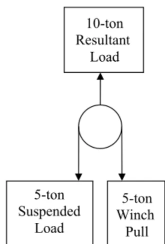
Figure C.1—Illustration of the Resultant Load on a Single Sheave Block WRQ 5HVXOWDQW /RDG WRQ 6XVSHQGHG /RDG WRQ :LQFK 3XOO
ADDENDUM 1 TO PROCEDURESFOR INSPECTION, MAINTENANCE, REPAIR, AND REMANUFACTUREOF DRILLING EQUIPMENT 5
f. Prime movers intended to be used, such as the equipment specified in C.2.7, hydraulic, electric, or pneumatic motors, internal combustion engines, winches, and hoists which provide the power to lift and suspend the BOPs or BOP stacks shall not be capa-ble of inducing forces that exceed 110% of the design load of the system unless the load monitoring devices and operating procedures are developed and implemented by the user as outlined below. Load limiting devices may also be incorporated to limit such forces, such as circuit breakers, engine governors, pressure relief valves, pressure regulating valves, etc. Friction-type clutches do not qualify as a load limiting device.
• A load monitoring device shall be fitted and confirmed to be calibrated and in serviceable condition prior to BOP stack han-dling operations.
• The operator of the equipment shall ensure that the applied load indicated by the load monitoring device shall not exceed a value that will result in exceeding the safe working load of the BOP handling system as defined in C.6.
g. The resultant load on a single sheave block as illustrated in Figure C.1, and its attachment to supporting structure shall not exceed the documented working load limit of the sheave block as specified by the manufacturer.
h. Flexible hoses shall be selected, fabricated, tested, cleaned, and installed in accordance with the following guidelines:
• The use of flexible hoses shall be kept to an absolute minimum required to compensate for vibration, thermal expansion and contraction, misalignment, or relative movement required between the hose end terminations.
• Flexible hoses shall have a working pressure equal to or exceeding the piping system into which they are installed. The minimum burst pressure of flexible hoses shall be a minimum of 4 times the working pressure of the hose as specified by the hose manufacturer.
• Only hydraulically-crimped type hose end fittings shall be used. Swivel-type end fittings that are widely available are rec-ommended to be installed at each end of the hose to prevent hose twisting during installation and removal. No galvanized end fittings shall be used, and no Teflon tape shall be applied to any pressure sealing threaded connections, such as NPT (National Pipe Thread) threads.
• Raw hose body material used to fabricate hose assemblies shall not be older than 5 years from the date of manufacture, and shall be suitable for and compatible with the type of media being conveyed.
• Paint should not be applied to the outside of hose assemblies at any time
• All hose assemblies shall be internally cleaned to the extent necessary after pressure testing to ensure that any contamina-tion inside the hose assembly will not adversely affect system operacontamina-tion. Hose assemblies shall be capped and sealed after testing and cleaning.
• When installing hose assemblies, they shall be routed and secured in such a manner that will avoid kinking or bends in the hose body that are less than the published minimum bending radius. Additional protection for the hose outer cover shall be provided in way of contact with surfaces subject to vibration.
• Each hose assembly shall be pressure tested to a minimum of 1.5 times the working pressure of the hose body prior to clean-ing. Water should be used as the pressure testing media.
• When hose assemblies are fabricated by a qualified third party, the user shall request that the above requirements shall apply, and that a certificate be issued for each hose assembly to verify that such hose assemblies comply with the above requirements with the test pressure specified on the certificate. Each certificate should have a unique certificate number.
• A list of all hose assemblies utilized in a system is recommended to be maintained by the user to allow prefabrication of hose assemblies for replacement. Such a list should specify as a minimum, the hose manufacturer and part number, type and part number of the end fittings, overall length, and the working pressure of the hose assembly. If any hose assemblies are fabricated by a third party, the certificate number for each hose assembly should be included on this list.
i. For temporary or permanent BOP stack storage structures fabricated by the user, the design shall comply with the applicable requirements of API Spec 7K to determine the design load and applicable design safety factors. The design of these structures shall be based on either one or both of the following conditions in addition to the design criteria specified in API Spec 7K as applicable. In the event of any conflict between the conditions specified below, the most severe condition shall be utilized to develop the design.
• Survival conditions specified in the Operating Manual for the MODU on which the storage structure is to be installed. • For fixed installations, the same maximum wind velocity used for the design of the derrick shall be taken into account.
C.5.2 The following design factors shall be applied by a licensed engineer or a person who by education, training, and experi-ence can demonstrate the knowledge and skills required:
C.5.2.1 The applicable default dynamic factors specified in Table 1 of clause 9.13.4.2 of API Spec 7K shall be applied.
C.5.2.2 An additional factor of 1.3 shall be applied to account for a combination of the following forces: a. Maximum anticipated wind velocity;
b. Any potential side loading;
c. Additional dynamic forces induced by stopping and starting the lifting, lowering, or transverse movements;
d. Potential damage or deterioration of components in the primary load path if the system is intended to be permanently installed.
C.5.2.3 A safety factor of 2.5 shall be applied after applying the above factors. Exceptions are as follows:
a. For systems incorporating multiple load paths, if any one primary load path should fail while the system is in operation at the rated load, the stress in the weakest component in any of the remaining primary load paths shall not exceed 80% of the yield strength of the material;
b. For structural components, the minimum design safety factor specified above shall be derived by applying a scaling factor of 1.5 to the design loads and designing to the allowable stresses specified in American Institute of Steel Construction (AISC) Spec for Structural Steel Buildings Allowable Stress Design and Plastic Design (current edition).
C.5.3 The ratio of the sheave diameter or winch drum pitch diameter and the rope diameter shall be a minimum of 18 to 1 in order to maximize the fatigue life of the wire rope. Exceptions to this requirement may be taken when space constraints or other circumstances dictate smaller ratios. In these cases, sheaves and/or drums should be provided that have the largest ratio that can be installed, operated, and maintained in the space provided. For temporarily installed non-purpose-built systems utilizing single or multiple sheave blocks, smaller ratios may be utilized, but it is recommended that the lowest ratio not be less than 10 to 1. For permanent installations where wire rope is utilized with sheaves and winch drums yielding smaller ratios than 18 to 1 (regardless of whether they are purpose-built systems or not), the user shall assess and appropriately modify the frequency of visual inspec-tion and replacement of the wire rope to account for the reducinspec-tion of wire rope fatigue life.
C.5.4 BOP attachment points for lifting BOPs and / or BOP stacks should be specified by the original BOP or BOP stack man-ufacturer including any limitations. In the event that such information is not made available for whatever reason, alternative lift-ing methods which do not incorporate specific attachment points on the BOP or BOP stack may be utilized, such as wrapplift-ing it with a sling if designed in accordance with specifications and instructions provided by licensed engineer or a person who by edu-cation, training, and experience can demonstrate the knowledge and skills required.
C.6 Determination of safe working load
The user is responsible for determining the safe working load (SWL) of BOP handling systems in accordance with API Spec 7K. a. The SWL as defined in clause 3.0 of ISO 14693 is the design load reduced by the dynamic load.
b. The SWL shall not exceed the design load of the BOP handling system as defined in clause C.5 above.
c. If for whatever reason it is impossible to estimate with any accuracy or certainty what the dynamic load is, a dynamic factor of 1.33 shall be utilized for onshore or fixed offshore installations, and a dynamic factor of 1.5 shall be utilized for offshore floating
ADDENDUM 1 TO PROCEDURESFOR INSPECTION, MAINTENANCE, REPAIR, AND REMANUFACTUREOF DRILLING EQUIPMENT 7
installations. These factors shall be taken into account in addition to considering the effects of prevailing wind velocity, potential side loading, and the condition of the primary load path (s) as determined by visual means prior to system operation.
d. When procuring BOP handling systems that are designed and manufactured in accordance with API Spec 7K, and in connec-tion with the above, the user shall specify in the purchase agreement, the maximum dynamic forces and/or acceleraconnec-tions that the system would reasonably be subjected to, including but not limited to maximum wind velocity, accelerations imposed during transportation (if the system is portable) for installations on land rigs and fixed platforms. In the case of installations intended for floating MODUs, the user shall specify the maximum wind velocity and vessel motion criteria that the system would be subjected to for drilling operations as well as survival mode as documented in the MODU’s Operating Manual.
C.7 User-provided loose gear and wire rope utilized in the primary load path of
purpose-built BOP handling systems
C.7.1 For loose gear provided by the user as specified in C.2.2.g that are intended to be used in the primary load path of pur-pose-built systems designed and manufactured to API Spec 7K, the published working load limit of each loose gear component in the primary load path shall be no less than the design load of the BOP handling system as documented by the BOP handling sys-tem manufacturer.
Note: The design factor of loose gear is the ratio between the ultimate breaking strength and the working load limit as documented by the loose gear manufacturer. In some cases, the design factor of such loose gear may vary between 4 to 1 and 5 to 1. Under no circumstances shall the design factor of loose gear utilized to handle BOPs or BOP stacks be less than 4 to 1.
C.7.2 Wire rope provided by the user shall equal or exceed the specifications of the wire rope originally provided with the BOP handling system based on the system manufacturer’s wire rope specifications.
C.8 Load monitoring / indicating systems
C.8.1 For purpose-built systems the manufacturer is required to provide load monitoring / indicating devices when specified in the purchase agreement. As such, the user is responsible for specifying the desired capabilities of such devices. These capabili-ties may include but not be limited to real-time display of the load being handled, audio/visual alarms when the applied load reaches certain values, data loggers to record system operating and loading data, and automatic fail-safe shut-downs that will acti-vate when the load indicated by such devices reaches a specified percentage of the documented rated load of the system.
C.8.2 For non-purpose-built systems, a calibrated load cell shall be utilized in the primary load path between the BOP stack and the handling system, and a means of monitoring the load cell display shall be provided so that the actual weight of the BOP stack can be determined during the initial phase of handling.
C.9 System installation requirements
The following shall be regarded as minimum requirements for the installation of both purpose-built and non-purpose-built BOP handling systems:
a. All welding shall be performed in accordance with a qualified welding procedure, and all welders shall be qualified to the welding procedure that they are assigned to perform. Such procedures and qualifications shall be documented.
b. Selection, fabrication, cleaning, testing, and installation of flexible hose assemblies shall comply with the guidelines provided in C.5.1 g).
c. Traceable documentation shall be available to verify that all pressure vessels, including air / liquid pressure accumulators uti-lized in the system meet the following minimum requirements:
• The maximum allowable working pressure of the pressure vessel shall meet or exceed the working pressure of the piping systems into which they are intended to be installed;
• All pressure vessels shall meet or exceed all applicable design and manufacturing codes and standards;
• Pressure-relieving devices shall either be installed on the pressure vessel or in the piping system in a manner such that they cannot be isolated from the pressure vessel in order to prevent pressurization above the designated maximum allowable working pressure;
• Inspection openings shall be provided on the pressure vessel to allow visual inspection of the internal surfaces;
d. Documentation shall be available for the following components and materials used to support or suspend the primary load only:
• Vendor certificates for wire rope, slings, and loose gear (Note: Slings and loose gear are defined in clause 3.0 of API Spec 7K). Such certificates shall, at a minimum, provide a serial number to identify the specific wire rope, sling, or piece of loose gear, and specify the breaking strength and / or working load limit (as applicable);
• Mill certificates for all steel plates or shapes;
• Documentation for welding consumables used for welding;
• Documentation of the welding procedures and welder’s qualification to such procedures;
e. Documented instructions and procedures for any system assembly, testing, and commissioning that is required to be performed at the installation site shall be available prior to commencing installation, which shall include, but not be limited to the following:
• A list of required lubricants and special tools;
• Adjustment procedures required after assembly of the system or sub-systems; • Wiring diagrams and system electrical connection drawings;
• Specifications for the connection of rig-supplied utilities to the system, including but not limited to electrical power, instru-mentation and control system wiring, and piping connections for compressed air, hydraulic power, and water;
• System commissioning procedures including but not limited to function and load testing procedures;
f. An inventory of spare parts, raw materials, lubricants, and all equipment and expendable materials required to support the installation shall be procured and delivered to the site prior to commencing installation.
g. Arrangements for the supply and erection of scaffolding and work platforms shall be made for access to areas of the rig required for system installation.
h. Documented work planning and safety procedures shall be made available, including but not limited to the following: • Electrical power circuit and piping system pressure isolation and lock-out / tag out procedures;
• Fire prevention and control measures; • Job planning and risk assessment procedures; • Personal protective equipment and fall protection; • Personnel assigned to conduct safety audits;
i. Environmental protection procedures shall be available and communicated to the work force. j. Arrangements shall be made for third party witnessing and / or verification as required.
C.10 System commissioning requirements after initial installation
C.10.1 For purpose-built BOP handling systems installed on any rig, it shall be function tested, followed by a proof load test prior to commissioning the system for the first time. The proof load test value shall be at an amount specified by the system man-ufacturer. For proof load test values exceeding the static weight of the BOP stack and all of its attachments, a means shall be pro-vided to safely add the weight required to achieve the specified load. Alternatively, the system manufacturer may conduct a proof load test of the primary load paths of the system either independently, or at one time as a system at a separate facility. For attach-ments between the system and the rig that are designed to transmit the load to the rig structure, these may be independently tested at the same load and the same force vector direction that would be exerted on them if the system was installed and subjected to the specified proof load value.
C.10.2 Non-purpose-built systems shall be function tested, followed by a proof load test after initial installation to at least 1.25 times the static weight of the BOP stack and all of its attachments. When a means of creating the weight necessary to conduct this load test is not available or could create safety hazards to rig personnel, the load test shall be conducted under close scrutiny at the static weight of the BOP stack and all of its attachments. Such scrutiny shall be focused on all components in the primary load path to detect any initial deformation or cracking. A means shall be established to quickly and safely abort this load test without losing control of the movement of the BOP stack in the event of detecting initial failure of any primary load path component so that safety hazards to rig personnel are avoided. Alternatively, independent load testing of all primary load path components may be conducted as long as such testing satisfies all intents and purposes of the independent testing of the system and its attachments points on the rig as described in C.10.1.
ADDENDUM 1 TO PROCEDURESFOR INSPECTION, MAINTENANCE, REPAIR, AND REMANUFACTUREOF DRILLING EQUIPMENT 9
C.11 Periodic load testing requirements after initial installation and commissioning
C.11.1 Purpose-built systems, whether they are permanently installed or not may require load testing to a load value specified by the system manufacturer after initial installation and commissioning. Factors to be considered by the user to determine if and when load testing is required include but are not limited to the following:
a. When primary load carrying components have been remanufactured (as defined in Section 3), and such components or their attachments to the load path have not been warranted by the system manufacturer to be fit for service, and cannot be indepen-dently load tested prior to installation.
b. When measurable wear and / or corrosion limits to all primary load carrying components are not provided by the system man-ufacturer, and such components have been found to be visibly worn or corroded, and cannot otherwise be independently load tested, and it is desired by the user to continue operation of the system with such components installed.
c. When a means to measure the fatigue life-cycle limit of all primary load carrying components or the system itself are not pro-vided by the system manufacturer, the user should implement load testing at certain load values and intervals, based on system manufacturer’s recommendations.
d. When the limits specified in b) and c) above are specified by the system manufacturer, and the user does not replace, remanu-facture, or repair such components in a manner such that the systems or components are warranted by the system manufacturer that they are fit for service when such limits are reached or exceeded
C.11.2 No load testing of purpose-built systems shall be required, based on the following:
a. If the user replaces primary load carrying components prior to or when the limits specified in C.10.1 b) and c) are reached, and they have either been independently load tested or warranted by the system manufacturer to be fit for purpose prior to installation. b. When damaged or deteriorated components are replaced with new components, re-qualified components (used components determined to be in serviceable condition by the system manufacturer), or remanufactured components that have been warranted by the system manufacturer to be fit for service.
C.11.3 Non-purpose-built systems shall be load tested to 1.15 times the static weight of the BOP stack and all of its attachments prior to each system operation for as long as they are installed. When a means of creating the weight necessary to conduct this load test is not available or could create safety hazards to rig personnel, the load test shall be conducted under close scrutiny at the static weight of the BOP stack and all of its attachments. Such scrutiny shall be focused on all components in the primary load path to detect any initial deformation or cracking. A means shall be established to quickly and safely abort this load test without losing control of the movement of the BOP stack in the event of detecting initial failure of any primary load path component so that safety hazards to rig personnel are avoided.
C.12 BOP handling systems supported by the ground
For any system used for a land rig operation that is supported by the ground and is not installed on the rig, and where the rig struc-ture is not used to support or suspend the load, the primary load carrying components that transfer the load to the ground shall be visually examined by personnel familiar with the design of such systems for damage or deterioration prior to operation. In addi-tion, the user or personnel familiar with such systems shall also ensure that the ground in way of supporting the load is suitable for supporting the load at the rated load of the system. Ground preparation, such as the laying of sand or gravel, and/or the use of mats placed between the system contact points and the ground shall be performed to ensure the load will be evenly and adequately distributed into the ground at each contact point without undue penetration.
C.13 BOP stack or rig modifications resulting in load increases on purpose-built BOP
handling systems
C.13.1 Modifications to BOP stacks are highly probable over the life-cycle of any given rig. Whenever it is intended to modify a BOP stack to the extent that the static weight of the BOP stack and all of its attachments may increase, the user shall request the system manufacturer to conduct an analysis to determine whether modifications to the handling system, and / or revisions to the dynamic conditions within which the handling system can be operated are required. The user shall ensure that recommendations issued by the manufacturer are carried out and complied with.
C.13.2 Whenever rig modifications may impact the criteria upon which a purpose-built BOP handling system was designed to meet, the user shall request the system manufacturer to conduct an analysis of the proposed rig modifications to determine whether modifications to the handling system, and / or revisions to the dynamic conditions within which the handling system can
be operated are required. The user shall ensure that recommendations issued by the manufacturer are carried out and complied with.
C.14 Third party verification of purpose-built systems
Generally, if the purchase agreement requires third party certification of a purpose-built system, the manufacturer is responsible for making arrangements with such third parties, and the user is not involved, other than to ensure that copies of any certificates are maintained on file. However, the installation of purpose-built systems may require third party oversight to some degree, depending on applicable rig classification rules and / or regulatory requirements. Such oversight may include but not be limited to the verifying:
a. The system is certified to meet API Spec 7K and any other applicable requirements specified in the purchase agreement; b. The installation and any subsequent testing and commissioning activities meet all applicable rig class rules and / or regulatory requirements.
Information about API Publications, Programs and Services is avail-able on the World Wide Web at: http://www.api.org