Visual Calibration, Identification and Control of 6-RSS
Parallel Robots
Pengcheng Li A Thesis in The Department ofMechanical, Industrial & Aerospace Engineering
Presented in Partial Fulfillment of the Requirements for the Degree of
Doctor of Philosophy (Mechanical Engineering) at Concordia University
Montr´eal, Qu´ebec, Canada
June 2020
CONCORDIA UNIVERSITY SCHOOL OF GRADUATE STUDIES
This is to certify that the thesis prepared
By: Pengcheng Li
Entitled: Visual Calibration, Identification and Control of 6-RSS Parallel Robots
and submitted in partial fulfillment of the requirements for the degree of Doctor of Philosophy (Mechanical Engineering)
complies with the regulations of this University and meets the accepted standards with respect to originality and quality.
Signed by the final examining commitee:
Chair Dr. Anjan Bhowmick
External Examiner Dr. Zheng Hong (George) Zhu
External to Program Dr. Shahin Hashtrudi Zad
Examiner Dr. Brandon Gordon Examiner Dr. Youmin Zhang Thesis Supervisor Dr. Wen-Fang Xie Approved by
Dr. Ivan Contreras, Graduate Program Director
June 15, 2020
Dr. Amir Asif, Dean
Abstract
Visual Calibration, Identification and Control of 6-RSS Parallel Robots
Pengcheng Li, Ph.D. Concordia University, 2020
Parallel robots present some outstanding advantages in high force-to-weight ratio, better stiff-ness and theoretical higher accuracy compared with serial manipulators. Hence parallel robots have been utilized increasingly in various applications. However, due to the manufacturing tolerances and defections in the robot structure, the positioning accuracy of parallel robots is basically equiva-lent with that of serial manipulators according to previous researches on the accuracy analysis of the Stewart Platform [1], which is difficult to meet the precision requirement of many potential applica-tions. In addition, the existence of closed-chain mechanism yields difficulties in designing control system for practical applications, due to its highly coupled dynamics.
Visual sensor is a good choice for providing non-contact measurement of the end-effector pose (position and orientation) with simplicity in operation and low cost compared to other measurement methods such as the coordinate measurement machine (CMM) [2] and the laser tracker [3]. In this research, a series of solutions including kinematic calibration, dynamic identification and visual servoing are proposed to improve the positioning and tracking performance of the parallel robot based on the visual sensor.
The main contributions of this research include three parts. In the first part, a relative pose-based algorithm (RPBA) is proposed to solve the kinematic calibration problem of a six-revolute-spherical-spherical (6-RSS) parallel robot by using the optical CMM sensor. Based on the relative poses between the candidate and the initial configurations, a calibration algorithm is proposed to determine the optimal error parameters of the robot kinematic model and external parameters intro-duced by the optical sensor. The experimental results demonstrate that the proposal RPBA using optical CMM is an implementable and effective method for the parallel robot calibration.
The second part focuses on the dynamic model identification of the 6-RSS parallel robots. A vi-sual closed-loop output-error identification method based on an optical CMM sensor is proposed for the purpose of the advanced model-based visual servoing control design of parallel robots. By us-ing an outer loop visual servous-ing controller to stabilize both the parallel robot and the simulated model, the visual closed-loop output-error identification method is developed and the model param-eters are identified by using a nonlinear optimization technique. The effectiveness of the proposed identification algorithm is validated by experimental tests.
In the last part, a dynamic sliding mode control (DSMC) scheme combined with the visual servoing method is proposed to improve the tracking performance of the 6-RSS parallel robot based on the optical CMM sensor. By employing a position-to-torque converter, the torque command generated by DSMC can be applied to the position controlled industrial robot. The stability of the proposed DSMC has been proved by using Lyapunov theorem. The real-time experiment tests on a 6-RSS parallel robot demonstrate that the developed DSMC scheme is robust to the modeling errors and uncertainties. Compared with the classical kinematic level controllers, the proposed DSMC exhibits the superiority in terms of tracking performance and robustness.
Acknowledgements
More than four years of doctoral career is coming to an end. Every step of my growth is insep-arable from the encouragement and help of mentors, families and friends.
Here, I sincerely thank you. First of all, I would like to take the opportunity to greatly thank my supervisor, Dr. Wen- Fang Xie for her nonstop supports, suggestions, and guidance, not only on my research, but also in life. She enrolled me into the door of the subject area and let me have the chance to do the research, which change my life to a wonderful world. I am deeply inspired by her careful thinking, unremitting and rigorous work attitude, broad and profound knowledge. Whenever encounter difficulties, I can always be encouraged by her with patient guidance and full enthusiasm in time. The period of working with Dr. Xie will be the wealth that accompany and benefit me all my life. On the completion of this thesis, I would like to to express the most sincere gratitude, the highest respect and the best wishes to my supervisor for all her contributions, guidance and encouragements.
Hearty thanks also go to my colleagues and friends who accompanied me along these years: Dr. Dongdong Zheng, Dr. Xiaoming Zhang, Dr. Rui Zeng, Dr. Shutong Li, Mrs. Tingting Shu, Mr. Ronghua Zhang, Mr. Xiaoyang Zhang and Dr. Ahmad Ghasemi. I would like to thank my professor Dr. Wei Tian who gives me guidance and support. I am also grateful to all those people who have given me support and I didn’t have the chance to thank them. I ultimately would like to thank my lovely parents Mr. Keming Li and Mrs. Xiaoli Min for their support, regardless of my choices, and for having allowed me, with their efforts, to get to where I am now. My deepest heartfelt gratitude goes out to my wife, Mrs. Jianyun Chen. She supported and encouraged me from the very beginning step of my PhD study to the end. I am really grateful for having her in my life.
Dedicated to my beloved wife,
Jianyun Chen
and my lovely parents,
Keming Li
and
Table of Contents
List of Tables x List of Figures xi 1 Introduction 1 1.1 Background . . . 1 1.2 Motivation. . . 31.3 Problems and Solutions . . . 6
1.4 Scope and Objectives . . . 8
1.5 Contributions . . . 9 1.6 Publications . . . 10 1.7 Thesis Organization . . . 12 2 Literature Review 13 2.1 Introduction . . . 13 2.2 6-RSS Parallel Robot . . . 13
2.3 Kinematics of the Parallel Robot . . . 16
2.4 Dynamics of the Parallel Robot . . . 17
2.5 Visual Kinematic Calibration of the Parallel Robot . . . 19
2.6 Dynamic Identification of the Parallel Robot . . . 22
2.7 Visual Servoing Control for the Parallel Robot . . . 24
3 Kinematic Analysis and Dynamic Modeling of the 6-RSS Parallel Robot 28
3.1 Introduction . . . 28
3.2 Description of the 6-RSS Parallel Robot . . . 29
3.3 Inverse Kinematic Modeling of the 6-RSS Robot . . . 31
3.4 Forward Kinematic Solution of the 6-RSS Paralllel Robot . . . 33
3.5 Velocity Analysis of the 6-RSS Parallel Robot . . . 36
3.6 Dynamic Modeling of the 6-RSS Parallel Robot . . . 39
3.7 Summary . . . 42
4 Visual Kinematic Calibration Method for the 6-RSS Parallel Robot 43 4.1 Introduction . . . 43
4.2 Kinematic Error Model and Pose Estimation . . . 45
4.2.1 Kinematic Error Analysis . . . 45
4.2.2 Pose Estimation Using the Optical CMM . . . 46
4.3 Calibration Algorithm Based on the Optical CMM . . . 49
4.3.1 Implicit Calibration Method Based on the Optical CMM . . . 49
4.3.2 RPBA Based on the Optical CMM . . . 51
4.3.3 Constraints Determination for Robot Configuration Selection. . . 53
4.3.4 Identifiability and Observability Index . . . 54
4.4 Simulation Case Study . . . 55
4.4.1 Actuator Stroke for Calibration Configuration Determination . . . 55
4.4.2 Optimal Set of Calibration Configurations Selection Simulation . . . 57
4.4.3 Calibration Simulation . . . 58
4.5 Experimental Validation . . . 63
4.6 Summary . . . 67
5 Visual Close-loop Output-error Identification Method for the 6-RSS Parallel Robot 68 5.1 Introduction . . . 68
5.2 Linear Form of the Dynamic Model . . . 70
5.4 Modified Exciting Trajectory . . . 74
5.5 The Procedure of Identification . . . 75
5.6 Simulation and Experiment Results. . . 76
5.6.1 Model Validation . . . 76
5.6.2 Identification Experiment. . . 79
5.6.3 Identified Results Validation . . . 85
5.7 Summary . . . 89
6 Dynamic Model-based Visual Servoing Control of the 6-RSS Parallel Robots 90 6.1 Introduction . . . 90
6.2 Dynamic Model Properties of the Parallel Robot . . . 91
6.3 Built-in Controller of the 6-RSS Parallel Robot . . . 95
6.4 Visual Servoing Controller Design . . . 96
6.4.1 Kalman Filter Design. . . 97
6.4.2 DSMC for Parallel Robot. . . 98
6.4.3 Torque to Position Converter . . . 102
6.5 Experiment Results . . . 103
6.5.1 Experiment 1 . . . 108
6.5.2 Experiment 2 . . . 109
6.6 Summary . . . 114
7 Conclusion and Future Works 115 7.1 Summary of the Thesis . . . 115
7.2 Future Works . . . 117
References 119
List of Tables
Table 4.1 The standard deviations of the noise distribution . . . 59
Table 4.2 The standard deviations of the parameter errors distribution . . . 59
Table 4.3 The error norms between nominal and calibrated values-normal for implicit calibration method . . . 60
Table 4.4 The error norms between nominal and calibrated values-normal for RPBA. . 61
Table 4.5 The RMS of the relative pose errors in simulation. . . 61
Table 4.6 The RMS of the relative pose errors in experiment. . . 67
Table 5.1 Initial dynamic model parameters of 6-RSS parallel robot. . . 78
Table 5.2 Identified parameters of 6-RSS parallel robot. . . 82
Table 5.3 The RMS levels of the pose trajectory errors. . . 85
Table 5.4 The RMS levels of the ten validation trajectory errors. . . 86
Table 5.5 Variation measure of the identification result. . . 88
Table 6.1 Experiment1- the RMSE and MAE levels of the three control schemes . . . 104
List of Figures
Figure 1.1 (a) The serial robot - Unimate [4], (b) Industrial serial robot [5] . . . 2
Figure 1.2 (a) The Stewart robot [6], (b) The Delta parallel robot [7] . . . 3
Figure 1.3 The AFP machine in Concordia University . . . 4
Figure 1.4 (a) The Y-shape tube, (b) The bicycle frame . . . 4
Figure 1.5 The collaborative AFP machine in Concordia University. . . 5
Figure 2.1 (a) The 6-RUS robot [8], (b) The 6-DOF mobile seat [9], (c) The 6-DOF flight simulator [10], (d) The 6-RSS parallel robot in Concordia University. . . 15
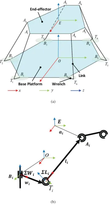
Figure 3.1 (a) The sketch of 6-RSS parallel robot, (b) Single serial branch. . . 29
Figure 3.2 The process of normal forward kinematic method . . . 35
Figure 3.3 The process of quasi-Stewart method . . . 35
Figure 4.1 Error parameters considered in the model. . . 45
Figure 4.2 The calibration system of 6-RSS parallel robot . . . 47
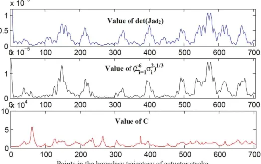
Figure 4.3 The determination of proper actuator stroke . . . 56
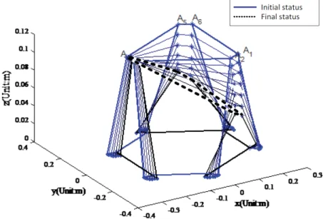
Figure 4.4 Bijective validation through the boundaries. . . 57
Figure 4.5 The simulation results of relative pose errors derived from implicit calibra-tion, relative calibration and un-calibration: (a) Along X Direction; (b) Along Y Di-rection; (c) Along Z DiDi-rection; (d) AroundαAxis; (e) AroundβAxis; (f) Around γ Axis . . . 62
Figure 4.6 (a) The 6-RSS parallel robot, (b) Architecture of the Experiment System . . 64
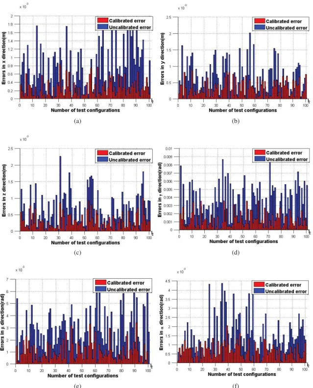
Figure 4.8 The experiment result of relative pose errors derived from calibrated model and uncalibrated model: (a) Along X Direction; (b) Along Y Direction; (c) Along Z Direction; (d) AroundαAxis; (e) Aroundβ Axis; (f) AroundγAxis. . . 66 Figure 5.1 The block diagram of closed-loop control system for model identification of
6-RSS parallel robot. . . 72 Figure 5.2 Sketch of the identification procedure. . . 76 Figure 5.3 Mechanical model of 6-RSS parallel robot built by SimMechanics. . . 77 Figure 5.4 3D animation of 6-RSS parallel robot.https://youtu.be/HXtCvgkn2jw. 78 Figure 5.5 Dynamic model validation block diagram of 6-RSS parallel robot. . . 79 Figure 5.6 Simulation results of SimMechanics model. (a) Position error; (b) Angle error. 80 Figure 5.7 Optimal exciting trajectory. (a) Positional trajectory; (b) Angular trajectory. 81 Figure 5.8 The pose trajectories of the parallel robot: the measurement of the real
plant (black dot), the output of the simulation with initial parameters (green line), the output of the simulation with identified parameters (blue line), (a) Along X Direction; (b) Along Y Direction; (c) Along Z Direction; (d) Aroundα Axis; (e) AroundβAxis; (f) AroundγAxis. . . 84 Figure 5.9 The pose trajectories of the parallel robot: the measurement of the real plant
(black dot), the output of the simulation with identified parameters (blue line), (a)
Along X Direction; (b) Along Y Direction; (c) Along Z Direction;(d) Around α Axis; (e) AroundβAxis; (f) Aroundγ Axis.. . . 87 Figure 6.1 The block diagram of the built-in controller for the individual joint . . . 95 Figure 6.2 The block diagram of the DSMC scheme for the parallel robot . . . 97 Figure 6.3 The block diagram of kinematic level controller (a) KCSC, (b) KJSC . . . . 103 Figure 6.4 Experiment1-the tracking performances of the three control schemes tested
on the 6-RSS parallel robot: the desired trajectories (blue solid line), the pose of KJSC scheme (purple dashed line), the pose of KCSC scheme (black dotted line), the pose of DSMC scheme (red dash-dotted line), (a) Along X Direction; (b) Along Y Direction; (c) Along Z Direction; (d) Around α Axis; (e) Around β Axis; (f) Aroundγ Axis . . . 105
Figure 6.5 Experiment1-the tracking errors of the three control schemes tested on the 6-RSS parallel robot: KJSC scheme (purple dashed line), KCSC scheme (black dotted line), DSMC scheme (red dash-dotted line), (a) Along X Direction; (b) Along Y Direction; (c) Along Z Direction; (d) AroundαAxis; (e) AroundβAxis; (f) Around γ Axis . . . 106 Figure 6.6 Experiment1- the Kalman filter results: the measurement from optical CMM
before Kalman filter (blue solid line), the output of the Kalman filter (black dash-dotted line), (a) Along X Direction; (b) Along Y Direction; (c) Along Z Direction; (d) AroundαAxis; (e) AroundβAxis; (f) Aroundγ Axis . . . 107 Figure 6.7 Experiment2-the tracking performances of the three control schemes tested
on the 6-RSS parallel robot: the desired trajectories (blue solid line), the pose of KJSC scheme (purple dashed line), the pose of KCSC scheme (black dotted line), the pose of DSMC scheme (red dash-dotted line), (a) Along X Direction; (b) Along Y Direction; (c) Along Z Direction; (d) Around α Axis; (e) Around β Axis; (f) Aroundγ Axis . . . 110 Figure 6.8 Experiment2-the tracking errors of the three control schemes tested on the
6-RSS parallel robot: KJSC scheme (purple dashed line), KCSC scheme (black dotted line), DSMC scheme (red dash-dotted line), (a) Along X Direction; (b) Along Y Direction; (c) Along Z Direction; (d) AroundαAxis; (e) AroundβAxis; (f) Around γ Axis . . . 111 Figure 6.9 Experiment2- the Kalman filter results: the measurement from optical CMM
before Kalman filter (blue solid line), the output of the Kalman filter (black dash-dotted line), (a) Along X Direction; (b) Along Y Direction; (c) Along Z Direction; (d) AroundαAxis; (e) AroundβAxis; (f) Aroundγ Axis . . . 112
Chapter 1
Introduction
1.1
Background
Today, industrial robots have been widely used in aerospace, automotive manufacturing, spe-cial processing, electronic package, and modern logistics industries. The industrial robots play important roles in processing, welding, cutting, spraying, handling, sorting and assembly, etc. And they have become indispensable for ensuring product quality, improving production efficiency, and reducing production costs. Generally speaking, industrial robots are mainly classified into two cat-egories according to their topological configuration: serial robots with serial topology and parallel robots with parallel topology. In addition, in recent years, there has also been a type of mixed configuration robot that integrates both serial and parallel structures.
The world’s first industrial robot with the serial topology, as shown in Figure1.1a, was invented by George C.Devol in 1961, and has been successfully used on general motors assembly lines [4]. Since then, various types of serial robots have been developed and have greatly promoted the process of industrialized production. After the 1980s, with the development of technologies such as controllers, drives, sensors, and high-level programming languages, industrial robots based on the serial topology has entered in the golden age of development. Robot manufacturers such as ABB, KUKA, FANUC, KAWASAKI, St¨abli, etc., have successively developed various types of serial robots, as shown in Figure1.1b, which are widely used in different fields of industrial production. To this date, the serial robot technology is relatively mature.
(a) (b)
Figure 1.1: (a) The serial robot - Unimate [4], (b) Industrial serial robot [5]
After entering the 1980s, with the continuous expansion of application fields and the diversifi-cation of production environments, higher requirements are posed on the performance of industrial robots, such as speed, accuracy, stiffness, and dynamic characteristics. Due to its own structural characteristics and error accumulation effects, the applications of the serial robot in some produc-tion and processing are limited. In this case, a class of parallel topology mechanism (parallel kine-matic machines) as a new type of industrial robot, a parallel robot, has attracted increasing interest in academic and industry society. Compared with serial robots, parallel robots have high stiffness, stable structure, strong load-bearing capacity, small error accumulation effect, small motion inertia and easy inverse kinematic solution etc. [11]. These characteristic allow the parallel robots to have a complementary relationship with serial robots in applications, and broad application prospects.
The theoretical structure of a parallel robot, dating back to 1943, was proposed for automatic painting by Willard L. V. Pollard. However, subject to the technical conditions at the time, the phys-ical mechanism was not built. As shown in Figure1.2a, a six-degree-of-freedom (6-DOF) parallel mechanism for a flight simulator, named as Stewart platform, was designed by British engineer in 1965 [6]. Since then, the parallel robot technology has been greatly promoted. Its application range covers the fields of motion simulators, machining process, medical tools, aerospace docking devices and micro-motion mechanisms, etc [12]. One typical parallel robot in Figure1.2bis the well-known Delta parallel robot, which claims to be the fastest pick-and-place robot in the world. Delta parallel robots are often used in high-speed sorting and packaging applications [7].
(a) (b)
Figure 1.2: (a) The Stewart robot [6], (b) The Delta parallel robot [7]
1.2
Motivation
Recently, the increasing need for high performance composite structures in various industries has greatly driven the development of the composite manufacturing technologies [13]. The tra-ditional manual production cannot meet the high efficiency, accuracy and quality requirement of emerging industry. This aspect has encouraged the development of new production technologies such as automated fiber placement (AFP) systems. The AFP technology automates the production of composite material structures using prepregs, which are present in the form of strips composed of impregnated fiber tapes (glass, carbon, etc.) of semi-polymerized resin. In the AFP system, a deposition head with the ability of heating and compacting the resin prepregs is mounted on a fiber placement machine or an industrial robot. The AFP system in Concordia University is shown in Fig-ure1.3. The Kawasaki robot carrying the deposition head lays up the prepregs traversing the surface of the tooling mandrels. In the process of manufacturing, the tooling mandrel is used as a mold to be wound around by the prepregs to form a certain structure of composite part. The mandrel will be removed after the part is cured. The current AFP systems can significantly improve the efficiency and quality of the production of composite materials. However, they are limited to the production of the open surfaces presenting a flat or contoured surface, or simple revolution parts such as cylin-ders or cones due to the insufficient degree-of-freedom (DOF) of the system and the difficulties in
Figure 1.3: The AFP machine in Concordia University
(a) (b)
Figure 1.4: (a) The Y-shape tube, (b) The bicycle frame
generating trajectories. Especially, the aerospace industry and the production industries of sports equipment are now exploring to use this technique for the production of structures with more com-plex geometries, like ”Y” tubes or the structures forming closed-loops such as bicycle frames, as shown in Figure1.4.
To be able to manufacture the structures with complex geometries, the flexibility of the AFP system should be improved. The collaborative robotic system consisting of two robots is a promising solution to increase the dexterity by employing one robot to hold the fiber placement head at the end-effector and another robot to hold the mandrel. The two-serial-robot collaborative system may not solve the fiber placement problem, since the serial robots tend to deform and lose the accuracy due to its cantilever structure, considering the weight of the mandrel and the compaction force.
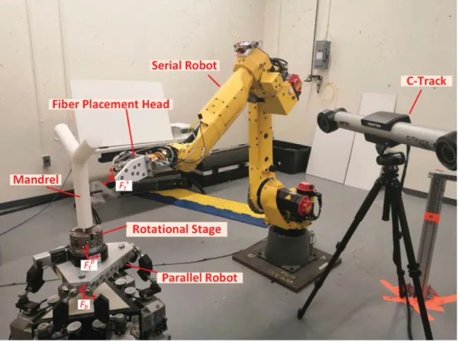
Figure 1.5: The collaborative AFP machine in Concordia University
Compared with the serial robots, 6-DOF parallel robots enjoy better stiffness. Therefore, a parallel-serial collaborative robot system, in additional to a rotational stage mounted on the platform of the parallel robot, is built for handling the complex structures manufacturing in Concordia University as shown in Figure1.5.
The positioning and tracking accuracy is one of the most important performance indicators of a parallel robot, which directly affects the final manufacturing results of the collaborative AFP system. However, the accuracy of the 6-DOF parallel robot is relatively low compared with the serial robot, which highly restricts the further development of the collaborative AFP system. With the gradual expansion of application fields, the requirements for the positioning and tracking accuracy of parallel robots are also increasing, especially in the fields of aviation, industrial finishing, medical assistance and micro motion. In practice, the accuracy of the 6-DOF parallel robots is relative low due to the existence of many factors affecting the motion error. Therefore, the research on
improving the positioning and tracking accuracy of parallel robots has important theoretical and practical significance, and thus is the main motivation of this thesis research work.
1.3
Problems and Solutions
The parallel robot motion error is referred to as the 6 dimension (6D) pose errors between the actual end-effector frame’s trajectory of the parallel robot and the ideal motion trajectory. There are many factors affecting the parallel robot motion error, and the source of the errors can be attributed to the mechanism errors and environment errors. The mechanism errors include geometric errors, flexible deformation, thermal deformation, force deformation and friction, etc. The environment errors mainly are introduced by the temperature, humidity, and operation process of the surrounding environment. According to the dynamic characteristics of errors, they can be classified into static errors and dynamic errors. Static errors remain constant during movement of the parallel robot, including structural errors, environmental factors, control systems, and transmission system error, etc. Dynamic errors change over time during the movement of a parallel robot, including flexible deformation of components caused by forces, inertial forces, and weight, etc [1]. The main errors of the 6-DOF parallel robot in this research are analyzed as following:
• Mechanism error. The errors of the basic components of the parallel robot during manufactur-ing and assembly are unavoidable, which result in errors between the actual parameters and ideal parameters of the components. Because the motion control of the parallel robot is based on the ideal structural parameters, it is not completely consistent with the actual structural parameters, which causes a mechanical error in the parallel robot and in turn leads to errors in the trajectory of the parallel robot. There are hundreds of error sources for structural errors of parallel robots, which are slightly different depending on the configuration. Generally, to simplify the calculation, only the length error of the links and the position error of the joints are considered [6]. The mechanism errors account for more than 60% of the total parallel robot motion error [1].
• Control system error. Joint position closed-loop controller is commonly used in the parallel robot control systems instead of workspace pose closed-loop controller, due to the lack of
the proper pose measurement device [12]. This control strategy is easy to be implemented, due to the fact that inverse kinematics of parallel robots can be analytically solved, and the measured joint angles can be used as feedback signal in the joint space control loop. However, the convergence of the joint positions cannot guarantee that of the 6D pose, according to the mechanism errors. Another issue of the current controllers of the parallel robots is that the dynamics of the parallel robots are ignored. The dynamic model of the parallel robot plays an important role in the model-based controller designs, especially in applications where high positioning and tracking accuracy is needed.
Kinematic calibration is a promising solution for removing the negative influence of mecha-nism errors and improving the positioning accuracy of end-effector output in a robot control sys-tem. Kinematic calibration is the process of determining the actual values of kinematic parameters of the robots which describe the relative position and orientation of links and joints in the robot. Basic steps of kinematic calibration are kinematic modeling, measurement and implementation [6]. Although a lot of methods for modeling and calibrating serial robots have been proposed, these methods are not always suitable for parallel robots. The existence of closed-chain mechanism and more moving parts yields difficulties on dynamic analysis of parallel robots. For example, a 6-DOF Steward platform has thirteen moving bodies (twelve legs and one end-effector), which are highly nonlinear in dynamic modeling. Since the dynamics parameters are normally unknown or approx-imately derived from CAD model for the industrial robots, the dynamic identification is necessary to be carried out.
Vision is a good choice for providing non-contact measurement of the end-effector’s pose with respect to the camera frame and has been utilized for kinematic calibration, dynamic identification and control of the robots [14,15]. Vision system can observe and estimate the complete end-effector pose in real time with simplicity in operation and low cost compared to other measurement methods, e.g. the laser tracker, and therefore, has a great potential for the calibration, identification and control of parallel robots. Vision can also be incorporated into the feedback control loop of robotic systems to increase the flexibility and adaptability. The pose of the end-effector can be acquired on-line provided that the image processing is fast enough. Shirai and Inoue [16] proposed an open-loop control method, so called ``look-then-move scheme´´, in 1973. With the development of high
speed computer, visual seroving, ``look-and-move´´control scheme, enjoys a fast progress. The most important advantage of visual servoing is to relieve control scheme from forward kinematics calculation. There is no analytical expression for the forward kinematic model of 6-DOF parallel robots [17]. Therefore visual servoing is an effective method for improving the tracking accuracy of parallel robots. Compared with the research work on visual servoing of serial robots [18,19], there are limited research work that has been dedicated to 6-DOF parallel robots.
The optical Coordinate Measurement Mechine (CMM) sensor is a dual camera based vision sensor. The coordinates of target reflectors in the field of view can be directly measured by the sensor. By attaching four non-collinear reflectors on the platform, the pose of the end-effector can be derived. The optical CMM sensor have been applied to the path tracking controller design [20] for the serial robots. In this research, the optical CMM sensor is utilized to measure the end-effector’s pose.
1.4
Scope and Objectives
The main goal of this research is to improve the positioning and trajectory tracking accuracy of the 6-DOF parallel robot by developing efficient kinematic calibration, dynamic identification, and control algorithm based on the optical CMM.
The research work in this research is carried out in four main phases. Firstly, the theoritical models related to the accuracy of the parallel robot, including inverse kinematics, forward kinemat-ics, velocity relations and the dynamic model of the 6-RSS parallel robots are needed to be built for developing visual calibration, identification and controller purpose. In the second phase, a calibra-tion algorithm by using the optical CMM and several target reflectors attached on the end-effector is presented for the 6-RSS parallel robot. The detected feature points of the reflectors can be used to estimate the poses of the end-effector. Correspondingly, the methods of constructing the objective function, finding the updating algorithm, selecting candidate configuration set and determining the proper working range are developed for the visual kinematic calibration purpose.
The third phase is the development of the dynamic parameter identification method for 6-RSS parallel robot based on the optical CMM. Due to the fact that it is normally nontrival to measure the
torque or current of the actuators of the industrial robots. The closed-loop output-error identification method based on the optical CMM is developed for the 6-RSS parallel robots, which is to find the dynamic model parameters by minimizing the output deviation between the actual and simulated systems subjecting to the same input.
Finally, in order to improve the tracking performance of the 6-RSS parallel robot, the dynamic model based visual servoing controller should be studied. Based on the calibrated kinematic and identified dynamic parameters, the computed torque visual servoing controller can be developed to derive good tracking performance. However the un-modeled dynamics and disturbance cannot be avoided, hence a sliding mode-based visual servoing controller can be developed to compensate the uncertainties and further improve the tracking performance. Due to the lack of the velocity measurement, the state variables estimation should be studied based on the pose measurement. At last, the stability analysis of the visual servoing controller needs to be given to guarantee the stability of the designed controller.
1.5
Contributions
In this Ph.D. project, a series of solutions for improving the positioning and tracking accuracy of the 6-RSS parallel robot are proposed based on a dual camera based optical CMM sensor. The main contributions of this project are summarized as following:
• The inverse kinematics and numerical solution of the forward kinematics for the 6-RSS par-allel robot are derived. The velocity analysis of the 6-RSS parpar-allel robot is given. The explicit dynamic model of the parallel robot is built based on the virtual work theory for the visual identification and servoing purpose.
• A relative posture-based algorithm is proposed to solve the kinematic calibration problem of a 6-RSS parallel robot by using the optical CMM sensor. This method applies both the po-sition and orientation variations and does not need the accurate location information of the detection sensor. The simulation results validate the effectiveness of the algorithm under dif-ferent circumstances. And the experimental results demonstrate that the calibrated kinematic parameters can be used to improve the positioning accuracy of the parallel robot.
• A closed-loop output-error identification method based on the optical CMM sensor is pro-posed for the 6-RSS parallel robot. The end-effector pose is measured by the optical CMM and served as the output of the real plant. The forward kinematics of parallel robots, which is usually solved by using time-consuming numerical algorithm, can be avoided. The exact knowledge of the built-in controller and the joint torque are not needed. The dynamic model parameters are identified by using nonlinear optimization technique. The experimental tests validate the identification results.
• A dynamic sliding mode control (DSMC) scheme is proposed to improve the tracking ac-curacy of the 6-RSS parallel robot. The proposed control scheme adopts the optical CMM sensor to obtain the real time pose information of the end-effector of parallel robot and to use it as the feedback signal. The DSMC scheme is robust to the modeling errors and un-certainties. With the benefit of the position-to-torque converter, the proposed DSMC scheme can be implemented in the industrial parallel robot. The stability of the proposed scheme has been proved by using the Lyapunov function. The experimental tests of the proposed control scheme have been carried out on the 6-RSS parallel robot. The comparison with the kinematic level controllers demonstrates the superiority of the proposed dynamic level visual servoing.
1.6
Publications
The achieved research results of this Ph.D. project have been submitted and published in the following journal and international conference papers.
Journal papers:
(1) Pengcheng Li, Xiaoming Zhang, Wen-Fang Xie, and Suong Van Hoa. Operation of the collab-orative composite manufacturing (CCM) system.JoVE (Journal of Visualized Experiments), (152):e59969, 2019.
(2) Pengcheng Li, Ahmad Ghasemi, Wen-Fang Xie, and Wei Tian. Visual closed-loop dynamic model identification of parallel robots based on optical CMM sensor. Electronics, 8(8):836, 2019.
(3) Ahmad Ghasemi, Pengcheng Li, and Wen-Fang Xie. Adaptive switch image-based visual servoing for industrial robots. International Journal of Control, Automation and Systems, 18(5):1324-1334, 2020.
(4) Ahmad Ghasemi, Pengcheng Li, Wen-Fang Xie, and Wei Tian. Enhanced switch image-based visual servoing dealing with featuresloss.Electronics, 8(8):903, 2019.
(5) Pengcheng Li, Rui Zeng, Wen-Fang Xie, and Xiaoming Zhang. Relative posture-based kine-matic calibration of a 6-rss parallel robot by optical coordinate measurement machine. Inter-national Journal of Advanced Robotic Systems, 15(2):1729881418765861, 2018.
(6) Dongdong Zheng, Pengcheng Li, Wen-Fang Xie, and Dan Li, Identification and control of flexible joint robot using multitime-scale neural network, Journal of Shanghai Jiao Tong University (Science), 25(4/5), 2020.
Submitted Journal paper:
(1) Pengcheng Li, Wen-Fang Xie, and Wei Tian. Dynamic visual servoing of a 6-RSS parallel robot based on optical CMM.IEEE/ASME Transactions on Mechatronics. Under review.
Conference papers:
(1) Pengcheng Li, Ahmad Ghasemi, Wen-Fang Xie, and Wei Tian. Visual Sensor-Based Dynamic Identification of a 6-RSS Parallel Robot. InProceedings of Eighth International Conference on Control, Automation & Information Sciences (ICCAIS 2019), Chengdu, China, October 23–26, 2019.
(2) Pengcheng Li, Wen-Fang Xie, Xiaoming Zhang, and Rui Zeng. Relative posture-based kine-matic calibration of a 6-rss parallel robot by using a monocular vision system. In Proceed-ings of 2017 IEEE International Conference on Robotics and Biomimetics (ROBIO), Macao, China, December 5–8, 2017.
1.7
Thesis Organization
The rest of this thesis is organized as the followings. In Chapter 2, a literature review of the main topics including the 6-RSS parallel robot, kinematic problems, dynamic modeling, kinematic calibration, dynamic identification and visual seroving of the parallel robot are given. The inverse and forward kinematic models of the 6-RSS parallel robot are built and the velocity analysis is presented in Chapter3. Then the explicit dynamic model of the parallel robot is derived based on the virtual work theory. In Chapter4, a relative pose based calibration method based on the optical CMM sensor is proposed. The visual closed-loop output-error identification method for the 6-RSS parallel robot is developed in Chapter5. Then a dynamic model based visual servoing method for the 6-RSS parallel robot is introduced in Chapter6. At last, the conclusion and further works are summarized in Chapter7.
Chapter 2
Literature Review
2.1
Introduction
The research content of this thesis involves the kinematic and dynamic modeling, kinematic calibration, dynamic identification and visual servoing control of the 6-RSS parallel robot based on the visual sensor. In terms of strategies and other aspects, the following is a review of the current research status in related fields.
2.2
6-RSS Parallel Robot
In the field of 6-DOF parallel mechanisms, most researchers have focused on six-spherical-prismatic-spherical (6-SPS) or six-universal-six-spherical-prismatic-spherical (6-UPS) parallel mechanisms, which are so-called Stewart platforms. Both the moving platform and the fixed base platform of Stewart parallel robot are hexagons connected by six SPS or UPS branch chains. Six moving prismatic pairs are used as inputs, and the two ends of the moving pair are connected to the moving and base platforms with spherical pairs respectively. The branch chains are symmetrical, and hence, Stewart platform is also described as 6-SPS or 6-UPS parallel robot. The number 6 represents the number of branches, and SPS represents the branch kinematic chain, which consists of a spherical pair (S), a prismatic pair (P) and a spherical pair (S) connected in series. In fact, almost all existing 6-DOF parallel robot, including those used for entertainment or motion (especially flight) simulators, are
based on the 6-SPS or 6-UPS mechanism. However, few people have studied on the 6-RSS type parallel robot which has almost the same characteristic as the Stewart platforms. In the 6-RSS par-allel robot, the revolute joint (R) is used as the driving pair, and the spherical pair in each branch can be interchanged with the universal joint (U), which does not change the nature of the mechanism. Therefore, the 6-RSS parallel robot has no difference from the 6-RSU and 6-RSU parallel robot in terms of kinematic analysis. As shown in Figure2.1a, a 6-RUS parallel machine tool has been de-veloped by Prof. Yukio Takeda of Tokyo Institute of Technology [8]. The most widely used one of this type of parallel robot is the Hexa robot proposed by Pierrot et al. Its variants, such as the Delta robot, have been applied in high speed pick-and-place fields [21]. For commercial applications, Servos & Simulation Inc. has designed an industrial 6-RSS parallel mechanisms which is used in this project. The 6-DOF mobile seat in Figure 2.1bis an application of the robot. The low-cost flight simulator based on the 6-RSS parallel robot is developed by Fidelity Flight Simulation Inc., as shown in Figure2.1d[10].
Compared with the traditional Stewart platform, the 6-RSS parallel robot has the following main advantages:
(1) Simple mechanism, short transmission chain and fast response;
(2) The heavy motors are installed on the base, so that the weight of the moving parts is reduced;
(3) Low cost electric drivers can be used.
The disadvantages associated with 6-RSS robot are listed as following:
(1) Since the legs of the serial chains are more complicated in the 6-RSS parallel robot, the kinematic analysis is complex;
(2) There are more factors affecting the positioning error of the moving platform. And thus it introduces more difficult error analysis.
The 6-RSS parallel robot in Concordia University, as shown in Figure2.1d, is taken as the case study in this research.
(a) (b)
(c) (d)
Figure 2.1: (a) The 6-RUS robot [8], (b) The 6-DOF mobile seat [9], (c) The 6-DOF flight simulator [10], (d) The 6-RSS parallel robot in Concordia University
2.3
Kinematics of the Parallel Robot
The kinematic study of a 6-DOF parallel robot considers the relationship between the six active joint inputs and the pose of the moving platform. The research content includes two parts: inverse kinematic solution and forward kinematic analysis. The inverse kinematic analysis aims to deter-mine the input of the motion by giving the pose of the platform. The forward kinematic analysis aims to calculate the pose of the platform by taking the active joint inputs as known parameters. The forward and inverse kinematic analysis is the core content of kinematic research of parallel robots, and it is also the theoretical basis for developing algorithms for the accuracy improvement.
The axes of translation and rotation of passive joints in the kinematic chain of a parallel robot are often designed to be intersective, so that the rotation angle or displacement of the passive joints can be eliminated when solving the kinematics equations. At the same time, each kinematic chain is structurally independent of each other, which makes the inverse kinematics problem very simple to obtain analytical solutions. In contrast, due to the combination of the position and attitude of the moving platform, the forward kinematics problem is to solve highly nonlinear equations to obtain the pose parameters, which is quite complicated and has not yet been completely solved [6].
There are two types of methods for solving forward kinematics: analytical methods and numer-ical methods. In terms of analytnumer-ical methods, algebraic elimination method, continuous method, interval analysis, etc. are used to transform the kinematics equations into a higher-order polynomial equation, which are committed to finding all possible solutions to the equation [6]. However, so far the forward kinematic solution cannot be expressed as explicit forms of the pose variables [6,17]. Moreover, finding all possible solutions does not completely solve the problem of forward kinemat-ics, and it is still necessary to further determine the only actual pose in these solutions, which is necessary in practical applications. In some cases, a univariate higher-order algebraic equation or a series of nonlinear equations can be solved by analytical methods, and additional sensors must be used to obtain the unique solution [22, 23]. However, there are limitations in practical appli-cations, due to the expensive measurement device and measurement noises. In terms of numerical methods, the Newton-Raphson method is widely used. This method aims to linearize a series of nonlinear algebraic equations to linear equations. Its convergence domain depends on the nature
of the nonlinear equations and if the initial pose of the iteration is in the convergence domain, the exact solution can be derived [6,24]. Some scholars use neural network algorithms to obtain the initial values required by Newton-Raphson algorithm to ensure the stability of the algorithm [25]. The optimization algorithms such as genetic algorithms and neural network algorithms have been developed to solve kinematic equations to obtain unique solutions [26,27]. However, those meth-ods can derive the exact solution with a satisfied accuracy only when the initial pose and the target pose are inside a small workspace. And if the target pose is close to the singularity configurations, the solution may converge to a local minimum. In this research, an effective and robust method for solving the forward kinematic solution of the 6-RSS parallel robot needs to be developed for the kinematic calibration purpose.
2.4
Dynamics of the Parallel Robot
The main purpose of dynamic modeling is to study the relationship between the driving force of the robot’s motion platform and the motion states (displacement or angle, translation speed or angular velocity, translation acceleration or angular acceleration) of the platform, and to obtain the dynamic equation of the driving forces or torques and motion states, which describes the dynamic characteristics of the robot. The dynamic model is the basis for the design of the robot control sys-tem. Similar to the dynamics of a serial robot, the dynamic model of a parallel robot also includes two most basic problems, namely the inverse and forward dynamic solution [6]. The forward dy-namic solution is to determine the motion of the parallel robot by knowing the main force or torque acting on the driving joint. On the other hand, if the motion of the reference frame of the end-effector platform is given, the main force or torque of the driving joint is calculated in the inverse dynamic problem. For both problems, the mathematical model of robot dynamics must be built.
The parallel mechanism is a complex spatial closed-chain mechanism. Compared with the serial robot, the number of moving components is doubled, and there exists coupling among the compo-nents, which makes the dynamic equation quite complicated. It is necessary for the researchers to establish the dynamic model to carry out the dynamic performance evaluation, dynamic opti-mization design and real-time control of the parallel robot [11]. The parallel robot theoretically
has the advantages of high rigidity, small inertia, large bearing capacity, high speed, high precision, etc. [28]. However, the existence of non-linear relations in parallel structures leads to complex forward position solutions, rich singular configurations, small working space, difficult control im-plementation, and hence, it is difficult to achieve precise control. This is a bottleneck in developing algorithms to improve the accuracy of parallel robots. The high-precision control of parallel robots requires the introduction of dynamics control, and the establishment of accurate dynamic model is the primary issue for dynamics control. Since the parallel robot is a complex multi-degree of freedom, multi-variable, highly coupling and nonlinear system, its mathematical dynamic model is very complicated and the identification of the parameters of the model poses a great challenge to the researchers.
There are many methods for modeling the dynamics of mechanical systems based on analytical mechanics. Typical methods are Newton-Euler equation method, Lagrange equation method and virtual work method [11]. One important indicator to measure the pros and cons of various dynamics modelings is the amount of computational load to solve the dynamic modeling problem. In general, the Lagrange method has the largest calculation amount, followed by the Newton-Euler method, and the virtual work method has the smallest calculation load with the highest efficiency.
The Lagrange method mainly uses the basic principles of energy conservation law and mathe-matical tools of Lagrange equations to solve the dynamic modeling problems in the mechanism from the perspective of system energy. The Newton-Euler method mainly uses the Newton’s second law and momentum theorem from the perspective of force, which lists the Newton-Euler equation to solve the dynamic equations in the mechanism. Combining the principle of virtual displacement with the principle of D’ Alembert, the virtual work method can solve the dynamic modeling prob-lems of systems with ideal constraints. The equation established by this method does not contain the constraint reaction force, and the constraint reaction force can be eliminated.
Each method has its advantages and disadvantages. The Lagrangian method needs to solve the derivative of the generalized coordinate, which increases the difficulty and the amount of calcu-lation. The Newton-Euler method avoids the problem of solving the derivative of the generalized coordinate derivative, and can provide the internal forces for each individual body of the parallel
robot, which can benefit the mechanical design process of the parallel robot. However, the computa-tional load is high due to the large amount of equations. The virtual work method does not consider the ideal constraint reaction forces, and only performs the dot product and cross product operation of the vector without requiring derivative operations, which is beneficial to computer-aided oper-ations. Moreover, in the commonly used Newton-Euler method and Lagrange method, it is more difficult to deal with the dynamics of a robot with a closed-chain mechanism. This is because in both methods, the closed-chain mechanism need to be cut into several open chains at certain joints, and to obtain the binding force and torque there. In contrast, the virtual work methods are more efficient and suitable for the control design purpose since the reaction forces between the bodies of the parallel robot are not considered.
The dynamic models of 6-DOF Gough-Stewart parallel robot have been built by several ap-proaches such as Newton-Euler [28], Lagrangian formulation [29] and the principle of virtual work [30]. The published research work on 6-DOF RSS parallel robots is considerably scarcer compared with that on Stewart parallel robot. The dynamic models of one type of 6-DOF RSS parallel robot, in which the active rotation axes are coplanar, are built based on Newton-Euler equa-tions [31] or Lagrangian formulation [32] for dynamic analysis and tracking control purpose respec-tively. In this project, the dynamic model of a 6-DOF RSS parallel robot, where the active rotation axes are parallel to each other, is built based on the virtual work principle, and the explicit form of the dynamic model is derived for the identification and dynamic model-based visual servoing design purposes.
2.5
Visual Kinematic Calibration of the Parallel Robot
Normally, the positioning accuracy of un-calibrated parallel robots is significantly affected by the manufacturing and robot installation errors. Kinematic calibration can be implemented to re-move the negative influence of these errors and to improve the accuracy of end-effector output in a robot control system.
In most applications, the kinematic calibration is known as an optimization problem with redun-dant non-linear constraint equations. The methods such as classical non-linear algorithms [33,34],
bundle adjustment approach [35] and interval approach [36] are applied to solve it. The basic cal-ibration principle is to construct constraint equations, which reflect the relationship between mea-sured values (could be passive joint values or pose of the end-effector) and the input joint values at various poses, i.e. calibration candidate configurations, until the number of constraints is large enough to determine the errors of geometry parameters contained in constraint equations [6].
For a n DOF robot, at every calibration candidate configuration a set ofkconstraint equations must be formed as functions ofserrors of geometry parameters, ofwimmeasurable pose parame-ters and of the measurements at the current configuration. The minimum calibration configuration numbermshould satisfy:m×k≥s+m×w, in order that the constraint equation’s number is larger than the number of the unknown parameters. Since there are some noises in the data obtained from sensors and deviations in the robot modeling, the geometry parameters which exactly match the con-straint equations cannot be determined. Therefore the numerical analysis method which minimizes the sum of the squares of constraint equations can be employed to determine an optimal solution of the errors of geometry parameters. The principles for the configuration selection of parallel robot calibration have been given in some literature [37,38], in which the error-parameter Jacobian matrix is utilized to minimize the influence of measurement noise in all candidate configurations.
Although some researchers perform the calibration without using a robot’s kinematic model [39], most kinematic calibration methods construct the constraint equations based on the kinematic model [40, 41]. To derive the error parameters in the robot kinematic model, the model-based calibration is conducted in three steps: modeling, measurement and optimization [42].
Based on the geometric analysis, a kinematic error model can be constructed by considering the residual errors in kinematic parameters. Model-based kinematic calibration tries to rebuild a more accurate mapping between robot actuator outputs and the end-effector pose by determining those kinematic parameters. Precise parallel robot error model is built by using D-H method [33]. However, most researchers [43,44] choose a reduced model in the calibration considering that the contribution of joint manufacturing tolerances has a minor effect on the platform’s pose error. In other words, the manufacturing tolerances of the joints are neglectable. Nevertheless, the positional errors of the joint centers and the deviation of the active joint angles are the main reasons for the kinematic calibration.
The measurement sensors play an important role in the parallel robot calibration. It tries to collect enough information for the calibration. The sensors usually fall into two categories: contact measurement and contactless measurement. For the contact measurement type sensors such as translation detector [45], CMM [2], inclinometer [46] and double ball bar device [47], they collect various pose information of the robot end-effector directly for the kinematic calibration. However, they have to meet the strict installation requirements. And the installation errors affect the contact measurement results in different directions and with different magnitudes when the measurand is moving. While for the contactless sensors like camera [43], laser tracker [3] and optical CMM [48], it is more flexible to obtain the pose information of the end-effector. The contactless measurement can eliminate the sensor errors with the help of pre-calibration. Alternatively the sensor location uncertainties can also be viewed as external parameters in terms of the kinematic error model [43], which may increase the complexity of the error model and computation cost. Ideally, the detection of relative pose (the variation of robot position and orientation) is independent of the sensors’ location. The classic implicit calibration method proposed in [49] utilizes the closure relation of the kine-matic chains to form implicit constraint equations instead of pursuing the analytical solutions of the closure equations such as the inverse kinematic model. The implicit calibration method emphasizes that the errors are involved in the kinematic loop equations implicitly, rather than being explicit outputs of a conventional input-output formulation. By removing the requirement to express errors explicitly, the formulation allows the analyst to concentrate on all sources of error [49]. And the im-plicit calibration method has been effectively applied to H4 mechanism [43] and 6-UPS robot.[49] In those implicit calibration methods, the absolute pose of the end-effector w.r.t. the base frame are obtained with the employment of the contactless sensor.
Most researchers assume the sensor location is exactly known in the kinematic calibration exper-iment [2,36]. Hence both the absolute and relative poses for the calibration algorithm can be easily determined. However, to derive the pose of the base frame of robots w.r.t. sensor frame is usually a tedious and time consuming work due to the following reasons: (1) the manufacturers usually do not provide enough nominal dimension information of the robots; (2) the self-occlusion of the close structure of parallel robots results in measurement difficulties. If the sensor location is not known exactly, the existing absolute pose-based algorithms cannot be used for the kinematic calibration
directly. Ideally the relative pose information, i.e. pose variation, can be utilized in the calibra-tion to avoid the tedious measurement of the relacalibra-tionship between the base frame and the sensor frame. A relative position-based calibration algorithm [45] is carried out for parallel robots, where a simple measurement system with three distance gauges and a ball mounted on the end-effector is employed to measure the relative position movement. However the orientation accuracy cannot be evaluated. Since the gauges should be re-intalled with strict rules in every candidate configuration, the installation errors cannot be removed during the calibration.
In this research, to realize a flexible installation and to avoid the tedious measurement procedure of the sensor location, an optical CMM sensor ––C-track 780 from Creaform Inc. is adopted to detect the relative pose of the 6-RSS parallel robot.
2.6
Dynamic Identification of the Parallel Robot
The dynamic parameters are normally unknown or approximately derived from manufacturer specifications, which are not accurate enough for the dynamic model-based controller design. Sys-tem identification is an effective method to perceive the uncertain parameters in the dynamic model of the system, and has been applied to many engineering practices [50]. As a highly coupled multi-input/multi-output (MIMO) nonlinear system, industrial robots aroused great interest in the identification method. The literatures on the state-of-the-art identification methods can be found in [51, 52, 53]. For the industrial robots, the dynamic identification is normally performed in closed-loop, since the robotic system is open loop unstable. In [54], a MIMO closed-loop iden-tification based on weighted least square estimation has been applied to an industrial serial robot used in a planar configuration. In addition, other closed-loop identification methods with maximum likelihood, instrumental variable and related implementation issues on industrial serial robots are addressed in [55,56]. A new closed-loop output-error identification scheme has been adopted for the serial robots [57]. The output-error identification method aims at finding the dynamic model pa-rameters by minimizing the output deviation between the actual and simulated systems subjecting to the same input [58]. In [57], the identification procedure is implemented in a closed-loop control structure and the joint torque is the measured output, which avoids the estimation of the velocity
and acceleration from the measured joint position.
One potential issue of the above-mentioned identification methods is that joint torque measure-ment or a related control signal is needed for identification, which is not always available for the industrial robots, since the built-in controllers of many industrial robots are inaccessible and do not provide the torque actuation mode [59]. The input of built-in controllers is the position or velocity command, and the output is the joint torque which is inaccessible to the users. Hence the torque and current of the motors cannot be derived directly and it is not easy to install additional torque sensors to get the direct measurement. The unknown controller can be identified along with the dynamic parameters as introduced in [60]. However, joint torque measurement is still needed for identification purposes.
In [21,51,61,62], identification issues on the dynamic model of parallel robots have been dis-cussed. Most research works on dynamic identification of parallel robots are based on a simplified dynamic model, such as in [63,64,65]. Nevertheless, the systematic derivation of the full inverse dynamic model is proposed based on Jourdain’s principle in [62]. In addition, the identification procedure is carried out in two steps: 1. identifying inertial parameters and 2. estimating the vis-cous coefficients. In [61], the full parameters of robots’ dynamic model and the joint drive gains are identified based on the total least square method, and the method is tested on a 3-DOF Orthoglide parallel robot. Many identification methods for 6-DOF parallel robots in [21,61,62] come directly from those of serial robots. By rewriting the inverse dynamic model and friction model into a linear form with respect to the dynamic and friction parameters, the identification of the unknown param-eters can be done through least squares technique. However for 6-DOF parallel robots, to avoid solving forward kinematics, the regression matrix of the dynamic model is constituted of the pose state variables in the Cartesian space. In [21], only joint space state variables are measured and estimated. Therefore, the state variables in Cartesian space should be calculated through numerical computation of the forward kinematics, which is quite time-consuming.
One way to avoid computing the forward kinematics in the identification process is to directly measure the pose of the end-effector in the Cartesian space based on vision sensors. In [65], a camera-based dynamic identification procedure is given for a 4-DOF parallel robot with a heavily simplified dynamic model by considering only the inertia of the end-effector. Also, a vision sensor
based dynamic identification has been carried out on serial robots [66] and cable-driven robots [67], but seldom on parallel robots. The optical CMM sensor is a dual camera based vision sensor, which can provide the real-time pose information of the targets. The optical CMM sensor has been ap-plied to the kinematics calibration [68] and the path tracking controller design [20] for the robots. To increase the flexibility and tracking accuracy, vision can also be incorporated into the feedback control loop of the parallel robot systems to form the so-called visual servoing control. The visual servoing controller for parallel robot is superior to the joint space controller due to the fact that the kinematic errors introduced from transforming the desired trajectory in the Cartesian space into the one in the joint space in the joint controller can be avoided. The measured pose together with the visual servoing controller allows using the closed-loop output-error identification method [58] to identify the dynamic model of the parallel robot, and hence will be conducted in this research.
2.7
Visual Servoing Control for the Parallel Robot
How to design effective controllers to improve the positioning and tracking accuracy of the par-allel robots poses a challenge to the control community. The existence of closed-chain mechanism yields difficulties on the controller design, related to the fact that the dynamic models of parallel robots are normally more complicated than those of their serial counterparts, since the moving parts are highly coupled and more moving parts are needed to be considered. Moreover there is almost no analytical expression for the forward kinematic model of 6-DOF parallel robots [6,17]. The joint space controller similar to that of the serial robots is designed for parallel robots by translating the desired pose trajectory of the end-effector frame in Cartesian space into the one in the joint space through the inverse kinematics [21]. This control strategy is easy to be implemented, due to the fact that inverse kinematics of parallel robots can be analytically solved, and the measured joint angles can be used as feedback signal in the joint space control loop. However, it is more desirable to directly control the pose of platform of parallel robot in Cartesian space (i.e. Cartesian space controller) for the following reasons: 1. The pose of the end-effector can be directly controlled to follow the desired trajectory in the Cartesian space control strategy which leads to a better tracking accuracy than controlling the joint space states in the joint space controller, since the desired joint
trajectories are transformed from the Cartesian space to the joint space. Such trajectory transforma-tion will introduce deviatransforma-tion caused by inverse kinematic model errors and hence affect the tracking accuracy. 2. The pose control scheme in Cartesian space can also avoid computing the forward kinematics which normally has no analytic solution, provided that the pose can be properly mea-sured or estimated. Then the main challenge lies in how to measure the the pose of the end-effector as the feedback of states and incorporate the measured pose in the feedback control loop.
Visual servoing provides an effective way to control parallel robots’ pose with visual sen-sors. Two main visual servoing control structures, namely image-based visual servoing (IBVS) and position-based visual servoing (PBVS), have been developed for parallel robots [69]. In IBVS, the control signals are directly derived from the coordinates of a set of visual features and computed in the image space [14,70]. Since the 3D information reconstruction and image interpolation are not employed in this method, the camera calibration is not required and the errors caused by sensor and object modeling are eliminated [71,72]. However, the singularities, local minima and lost of the image features are the main problems of IBVS due to the lack of the control strategy in Carte-sian space. The problems arise especially when the difference between the initial and target views is large [20]. On the other hand, the PBVS control loop directly controls the pose in Cartesian space and allows the direct path planning in the Cartesian space [73]. This feature meets the requirement of industry where the accurate Cartesian path tracking is essential, such as welding, machining, and fiber placement. However, the main obstacle of PBVS lies in estimating the pose information by using the vision information, which usually needs the object model and well-calibrated cameras. Thanks to the optical CMM, the pose information of the target can be measured accurately in real-time with simple calibration steps [20,68,74]. Hence, PBVS scheme is a promising method to achieve high accuracy tracking performance of parallel robots for industrial applications.
Most recent visual servoing research work on parallel robots is dedicated to the kinematic level visual servoing design [12,70,73,75,76,77]. The dynamics of parallel robots are usually ignored or treated as uncertainties. In [76], a visual servoing controller is designed for the end-point posi-tioning of 3-DOF parallel robot via linear camera-space manipulation. A hidden robot concept is proposed in designing a visual servoing controller for parallel robots based on the leg observations [77]. Although the kinematic level visual servoing of parallel robot can achieve the position tracking
to some extent, the tracking performance will be sacrificed greatly without considering the dynamic model of the parallel robot. To include the dynamic model in the visual servoing, the modeling and identification of the dynamics pose a challenge to the control designers. The other issue is the implementation of designed controller in the commercial industrial parallel robots. In most cases, the industrial parallel robots are joint space closed-loop architecture control systems and the built-in controllers of the robots do not provide torque control mode or joint-torque sensors [59,78]. The built-in controller is inherently position or velocity controlled system. Therefore, the torque com-mand generated by the dynamic level visual servoing controller cannot be directly fed to the built-in controller. To solve this problem, the torque-to-position converter is to be designed. In [79], a P-type torque-to-position converter combined with the backstepping sliding mode control method is designed to apply dynamic model-based controller to the robot manipulators. The proposed torque to position converter in [80] is developed based on the identification of the linear actuator model and is applied to the humanoid robot without using the vision information. And in [59], a similar converter combined with robot dynamics and friction feedforward compensation is utilized to con-trol the humanoid robot. The above-mentioned research work illustrates that the torque-to-position converter has great potential to implement the dynamic level visual servoing control scheme on the position command industrial parallel robots.
For the parallel robots with the open-loop architecture control systems, a lot of dynamic model-based controllers have been developed such as iterative learning controller [21], adaptive controller [81] and robust controller [82]. In [21], the dynamic model identification and the dynamic model-based iterative learning controller are investigated to enhance the tracking performance of a 6-DOF parallel robot. In [81], an adaptive control scheme based on the robust integral of the sign of the error control theory is proposed and tested on a 3-DOF parallel robot. The robust controller for Stewart platform compensates the dynamic model represented in the joint space by transforming the Cartesian space states into the joint space and computing the bounding function in [82]. The robust control such as the sliding mode control (SMC) is known to deal with the uncertainties such as the modeling errors, frictions of the passive joints, sensor noise and time delay. SMC has been widely applied to the joint space position control of the parallel robots [83,84]. However, the liter-atures on the SMC based visual servoing of parallel robots are relative scare. In [85], the trajectory
tracking scheme of a 4-DOF parallel robot is proposed by utilizing a fuzzy logical SMC scheme and assuming the pose of the end-effector is available in their simulation test. The dynamic model-based controllers are easy to be implemented on the open-loop architecture robotic systems, but it is nontrivial to be implemented on the closed-loop architecture robotic systems. This research aims at developing a dynamic model-based visual servoing controller for the closed-loop architecture industrial parallel robot based on the optical CMM sensor.
2.8
Summary
In this chapter, a brief introduction of the 6-RSS parallel robot regarding its applications, advan-tages and weakness compared with standard Steward platform is given at first. Then the kinematic problems of the parallel robot including the inverse and the forward solutions are presented. The dynamic modeling methods of the parallel robot are summarized in Section2.4. The virtual work principle method is chosen to build the dynamic model of the 6-RSS parallel robot for the visual identification and control purpose. Then, the relevant studies on the kinematic calibration method to improve the positioning accuracy of the parallel robot are introduced. With the help of the op-tical CMM sensor, the relative pose-based calibration method can be developed to derive accurate kinematic parameters, since the method can avoid the tedious measurement of the relationship be-tween the base frame and the sensor frame. In Section2.6, the literature survey on the dynamic identification methods of the parallel robots are introduced. One of potential issues of the current methods is that the torque measurement of the robot is needed and it is not always available for the industrial robot. At last the visual servoing methods for the parallel robot are discussed. It is found out that most current methods are kinematic level controllers and more advanced dynamic model based visual servoing methods are needed to be further studied to improve the tracking accuracy of the parallel robot.
Chapter 3
Kinematic Analysis and Dynamic
Modeling of the 6-RSS Parallel Robot
3.1
Introduction
The kinematic analysis and dynamic modeling are the foundation of the kinematic calibration, dynamic identification and control of the parallel robot. The inverse kinematic problem of the 6-RSS parallel robot will be solved analytically. A quasi-Stewart method is developed to solve the forward kinematic problem of the 6-RSS parallel robot numerically. By performing the velocity analysis, the Jacobian matrices are derived, which will be used for building the dynamic model and determining the singularity-free and bifurcation-free actuator motion range. The explicit form of the dynam

![Figure 2.1: (a) The 6-RUS robot [8], (b) The 6-DOF mobile seat [9], (c) The 6-DOF flight simulator [10], (d) The 6-RSS parallel robot in Concordia University](https://thumb-us.123doks.com/thumbv2/123dok_us/390262.2543353/28.918.174.804.188.952/figure-robot-mobile-flight-simulator-parallel-concordia-university.webp)