. The GSM AT command set. The SMS service
.1 Introduction
Besides telephony data services are also offered to a GSM subscriber. By connecting a laptop computer, a personal digital assistant, a fax machine or other Data Terminal Equipment (DTE) to a GSM mobile station, a user can exchange data with dedicated data networks such as : PSPDNs (Packet Switched Public Data Networks –e.g X.25, Internet), CSPDNs (Circuit Switched Public Data Networks), ISDN or it can send/receive faxes to/from users connected to PSTN (Public Switched Telephone Network). GSM supports these mobile office applications in two ways [2]:
o it allows control of the mobile phone through an external device by retrieval and setup of
communication parameters
o it provides all necessary support for sending and retrieving short messages through to the mobile phone
– the Short Message Service
Remote control of the mobile station is achieved by using an AT (attention) command set that operates over a standard or emulated (Bluetooth or IrDA) serial interface. In order to be able to use software in PCs or PDAs to set up the data capabilities of a mobile phone, the GSM specification are indicating how a connection must be set up[1]:
GSM Network
Applications
Fig.1 Typical configuration for remote control of mobile equipment
According to the GSM specifications the mobile equipment (ME) must be able to connect to, or
to include, a Terminal Adapter (TA) whose role is to convert the AT commands and responses into ME
control and response strings. The choice to implement or not the TA inside the ME it is left at the
choice of the manufacturer. Also, the link between a PC or a PDA (denoted in GSM TE- Terminal
Equipment) and the TA can be wired or wireless. Actually the TA plays the role of a data circuit
equipment (DCE) and modern MEs have built-in TA functions. Besides GSM specific commands, AT
V.25ter commands [1] and other cellular standards (IS-95, IS-136) specific commands are also
implemented in a GSM ME.
.2 Functional split of the GSM AT commands set
The technical specification GSM 7.07 splits the set of AT commands into 6 functional blocks:
A.
General commands
Terminal adapter AT commands AT responses ME status ME controlThe general commands are allowing access to the ME identification: manufacturer, , software
version, revision identification,
IMEI – International Mobile Equipment Identity
,
IMSI
–
International Mobile Subscriber Identity
, General commands might be also used to select a
character set for the TE, the wireless network to be used etc.
B.
Call control commands
Call control commands are allowing:
- selection of the type of address (the type of the number used for dialing: international prefix
code, national etc)
- dialing from a phone book
- selection of the type of call : voice/data/fax
- selection of a particular bearer service (e.g. how data is transported inside a GSM PLMN –
synchronous/asynchronous transfer, 300Bps, 2400Bps …9600Bps, transparent or
non-transparent transfer)
- set up of some call control parameters: how often an incoming call can ring before entering
voice mailbox mode, how long the ME should wait for call completion etc.
- hanging up a call in progress
- set up of the Radio Link Protocol
- generation of extended error reports
- set up/check of HSCSD parameters for HSCSD compliant phones
- check/enabling /disabling V.42bis data compression
C.
Network service related commands
Several types of network commands are distinguishable:
-
commands that are displaying the subscriber number(s) (according to the PSTN/ISDN
numbering format) for voice/data services;
-
commands used for network registration and operator selection
-
commands for supplementary services management
D.
ME control and status commands
This type of commands are dedicated for:
-
handling ME power, keypad, display and ring indicator
-
selection/reading/ writing of phonebooks
-
set up of the real-time clock.
-
accessing SIM database records
-
checking received signal quality (7 level scaled)
-
setting up the language of the ME
E.
ME Errors
The AT commands belonging to this set are enabling/disabling reporting for errors related to the
functions of ME’s, AT commands syntax, TA malfunctioning etc.
G. GPRS commands
The GPRS related AT commands are allowing:
-
PDP context definition/activation/deactivation/displaying (
P
acket
D
ata
P
rotocol
; a PDP
context in necessary for enabling a packet switched data transfer and it consists of a PDP
address (typically an IP address) and of an access point name (
APN
– a string that identifies
the external data network to whom the user want to connect)
-
displaying of the class of a GRPS mobile station
-
selection of SMSC center for GPRS based transmission of SMSs
F.
SMS sending and reading commands
.3 The syntax of GSM AT commands
All AT commands are using
AT
as a prefix; a simple
AT
command must be always sent before
any other commands. All AT commands are ending with the
CR (carriage return)
character. Space
characters are ignored when parsing a command between the prefix AT and the CR character.
The format for a
basic
AT command is:
<
command
>
denotes a string containing the name of the command to be executed
[ ] - optional
-
parameters are optional, if more than one parameter is needed the separation is done using
comma string “,”.
Examples
:
ATP<CR>
- select pulse dialing,
ATE0<CR>
–disable echoing (echo – character received
by DCE are sent back to TE)
The syntax of an
extended
AT command is:
“+”
is used
for all commands belonging to this category
- more than one commands can be sent on the same command line; the syntax in this case is:
Example:
AT+CSCS<CR> = “GSM
”
(indicates to DCE that DTE uses the default GSM
character set)
.4 Read and test commands
AT commands that are accepting parameters have always an associated
read command
which
Example:
AT+CSCS?<CR>
(query for finding out the used character set)
Extended AT commands have always an associated
test command
which is used to check if the
command is supported by the ME and to query the possible values of the parameters of its parameters.
The syntax for test commands is:
Responses to AT command are in text mode. Several responses are possible:
-
“OK” responses are indicating a successful completion of a command
-
extended responses with the generic syntax:
<parameter> - string denoting the result code; if more than one result code exist, they are
separated by commas “,”
<LF> line feed character
<command>- string denoting the AT command that issued the extended response
If a command is not implemented on the modem or the command line contains invalid
parameters the “ERROR” result is returned to DTE. Extended error reporting is also
implemented.
Examples:
The response to a test AT command
AT+CSCS=?<CR
> might be :
+
CSCS: ("GSM","UCS2")<CR>
OK
<CR>
The response of the same command in read mode
AT+CSCS?<CR
> might look as below:
<CR>
+CSCS:”GSM” <CR>
When setting the character set
AT+CSCS=”GSM”<CR>
the response could be (if GSM
character set is supported):
<CR> OK
<CR>
In echoing is enabled this case the AT command is transmitted by the DCE back to the DTE
and appears as a prefix to the response code.
.5 General AT commands
1Command Description Responses Observation
AT checks the presence of a the DTE and the communication between mobile station and the application
OK
+CME:error AT + CGMI displays manufacturer
identification <manufacturer> OK AT + CGMM displays the mobiles station
model identification and the supported frequency bands (on some devices)
<model type> OK
AT + CGMR displays the software version
of the mobile station <software version> OK AT + CGSN displays the serial number of
the MS (IMEI) <IMEI> OK AT + CSCS=<ch. set>
AT + CSCS=?
Informs the mobile station which is the character set used by the DTE
OK
shows supported character sets AT + CIMI displays the GSM identity of
the MS (IMSI – International Mobile Subscriber Identity)
<IMSI>
OK IMSI identifies the SIM card AT+WS46=<n>
AT + WS46=?
Allows selection of the
wireless network OK shows the available wireless networks (12- GSM)
AT+GCAP displays the capabilities of the
mobile station <capability list> +FCLASS- can send/receive faxes + CGSM – GSM capable + DS – data services capable
. Call control commands
2Command Description Responses Observation
ATD<dialstring>; Dials a number for a voice
connection OK NO DIAL TONE ERROR
BUSY
NO CARRIER
If <dialstring> is ommited i.e ATD; a network detection is performed
ATD<dialstring> Dials a number for a data
connection same as above + CONNECT a bearer service must be selected previously ATD><Name>; Direct dialing from memory same as for
ATD<dialstring>; the user having <Name> stored in memory is called ATD>n; Direct dialing of a indexed
number from memory same ATD<dialstring>; as for The number placed at index n in the selected memory is dialed
ATA Answering a call OK
CONNECT CONNECT <parameters> NO CARRIER ERROR
ATH Hang up call OK
ERROR - command not working for incoming calls
AT+CMOD=n Call mode setting OK
AT+CMOD=? Shows supported values A typical response might look like: +CMOD: (0-2) OK 0- single mode 1- alternate voice/fax 2- alternate voice/data AT+CBST= [<speed>[,<name>[,<ce> ]]] AT+CBST=?
Selection of a bearer service OK for data calls only <speed>0-autobauding, …4 -4800bps, …7-9600 bps <name> 0- asynchronous 1- synchronous <ce> 0- transparent 1- non transparent Example: AT+CBST=0,0,0 shows supported values (see[1] for a complete description)
AT + CRC = n Controls how an incoming call
is signaled to the DTE OK AT+CRC=0 an incoming call is signaled by the RING string AT+CRC=1 an incoming call is signaled by
+CRING:<type of call> string
Example:
+CRING: VOICE
AT+CHUP Call hang up OK Similar to ATH, provided for
alternate data/voice services AT+CSTA=<type>
AT+CSTA=?
Selection of the address OK <type> equals 145, 129 for national or international numbering format
checks the possible formats.
Example: +CSTA (129,145)
ATT/ATP Select tone/pulse dialing OK AT+CRLP Set up of non-transparent data
services OK (descriptionsee[1] for ) a complete
AT+DS=
[<direction>[,<compressi on_negotiation>[,<max_ dict>[,<max-string>]]]] AT+DS=?
Data compression (LZW) OK Used for set up of data compression in the uplink or downlink direction.
checks supported values.
Example:
+DS: (0-3),(0,1),(512-2048),(6-32) (see[1] for a complete description)
AT+CHSD Display of supported HSCSD
parameters +CHSD: <mclass>,<maxRx>, <maxTx>,<sum>,<co dings>
OK
mclass- multislot class maxRx-maximal number of TS to be used in downlink direction maxTx-maximal number of TS to be used in uplink direction
TS a MS can use in both uplink and downlink directions
-codings – indicates the type of FEC coding accepted on the radio interface (see[1] for a complete description)
AT+CHST
=[<wAiur>[,<wRx>[,<to pRx>[,<codings>]]]]
Set up of HSCSD parameters
for transparent connections OK (descriptionsee[1] for ) a complete
AT+CHSN =[<wAiur>[,<wRx>[,<to pRx>[,<codings>]]]] Set up of HSCSD parameters for non-transparent connections
OK (see[1] for a complete
description)
. Network service commands
2Command Description Responses Observation
AT +CNUM Subscriber number MSISDN’s - returns the subscriber
MSISDN(s) AT+CREG=<n>
AT+CREG ?
Network registration OK
can be used to query registration status If n=2 the response AT+CREG? is: +CREG: <n>,<stat>,<lac>,<ci> OK
stat – registration status lac- Location Area Code ci- Cell Identity
AT+COPS=<mode>, [<format> [ , oper> ] ] AT+COPS=?
AT+COPS?
Operator selection mode – automatic (0),
manual (1)
format – long(0)/short(1) alphanumeric format oper – code of the operator (MCC/MNC)[1] displays available operators
checks the current operator name
AT+CLIP/CLIR=<n> Calling line identification
presentation/restriction <n>=0 disable/enable supplementary service
ME control and status
3Command Description Responses Observation
AT +CSQ Signal quality indicator +CSQ: <rssi>,<ber> <rssi>- received signal strength indicator 0: -113 dBm or less; 1: -111 dBm 2 to 30: -109 to –53 dBm 31: -51dBm or greater
99: not known or not detectable
<ber>: bit error rate
99: not known AT + CFUN=<n>
AT+CFUN?
-setting functionality of the
MS OK <n> 0 powers off the MS
<n> =1 software reset –check the
functionality (“1” is the typical response for a powered on MS with a valid SIM card) AT +
CKPD=<numeric string>
emulates the MS keyboard OK Example:
AT + CKPD=”*#06#” – displays IMEI on the MS screen
AT +CBC Battery charge +CBC: <bsc>,<bcl> <bsc>- battery/charger presence /absence <bcl>- battery charge level [ %] AT+CPBS=<string> AT+CPBS=? Selects a specific phonebook memory storage
Shows possible values for the memory storage
OK +CBPS ("ME","SM","DC","LD","FD", "MC","RC") SM- SIM card ME – mobile phone FD- fixed dialing DC – ME dialed called list
LD – SIM last calls MC- missed calls RS- received calls
AT + CPBR= <index1>[,<index2]
AT+CPBR=?
Display numbers from the selected phonebook
Shows it the command is supported AT+CPBR= <index1>,<number>, <type>,<text> +CPBR: <index2>,<number>,<type>, <text>] OK AT+CPBR= <list of indexes>),[<nlength>],[<tlength>] <type> 129 145 or 161 <name> contact name If <index2> is omitted only the number stored at index1 is displayed <nlength> - maximal length for <number> <nlength> - maximal length for <text>
Example: AT+CPBR=? +CPBR: (1-200),80,12 OK AT+CPBW=<index> [,<number>[,<type> [,<text>]]]
Phonebook write OK Parameters identical to
AT+CPBR
. Pre-assignments
1. What is an AT command?
2. State the purpose and the syntax of an AT read commands
3. State the purpose and the syntax of an AT test commands
4. Which are the AT commands used for finding out the serial number/software version/model/IMSI of
the mobile station?
5. Which is the AT command used for dialing a number? How distinction between voice and data calls
is done?
6. Which are possible storage locations on a mobile phone?
7. Which are the parameters of a bearer service (BS)? Describe how selection of a particular BS among
supported ones is done using AT commands
8. Which is the AT command that can be used for finding out the position of a mobile station inside a
GSM PLMN?
9. Describe how the list of available operators can be displayed on a PC using AT commands
10. Which is the sequence of AT commands that can be used to display the numbers stored on a SIM
card?
. Assignments
The ME used for testing the GSM AT command set are Nokia N70 and Sagem MyX 401
devices. Alternatively, the Cellular Emulator tool included in the Windows Mobile SDK can be used.
1. Set up a communication link over Bluetooth between the PC and one of the mobile phones listed
above
;
s
tart the serial port service
. In simulation mode acces the "Injection" tab in the Cellular Emulator.
2. Launch HyperTerminal and set up a serial connection to the device using the serial port indicated at
connection setup time.
3. Find out using AT commands which are the software version/model name/ IMSI/cellular network in
which the mobile phone can operate.
4. Which are the data capabilities of the mobile phone?. Write down the results.
9. Use the appropriate AT commands for initiating a voice call to the number 0264401571 and for
hanging up.
10. Can the phone
/simulator
operate in HSCSD mode?
12. Use the appropriate AT command for displaying the received signal level
13. Use the appropriate AT command for displaying the battery charge level
14. Use the appropriate AT commands for displaying the numbers stored on the ME memory.
15. Use the appropriate AT commands for displaying the best received base station
.1 The Short Message Service
.1.1 IntroductionThe Short Message Service (SMS) is one of the services offered by a GSM system. In recent years SMS witnessed an explosive success; as a teleservice offered by a GSM PLMN, the SMS was introduced starting from Phase 1 of the standardization process and evolved continuously during the subsequent phases.
.1.2 SMS technology
As defined by the GSM specifications SMS is a “mean for transferring short messages between a GSM MS and a short message entity (SME) via a service centre (SC)”. A short message entity if defined to be an entity (not necessarily in a mobile network) that can send or receive SMSs.
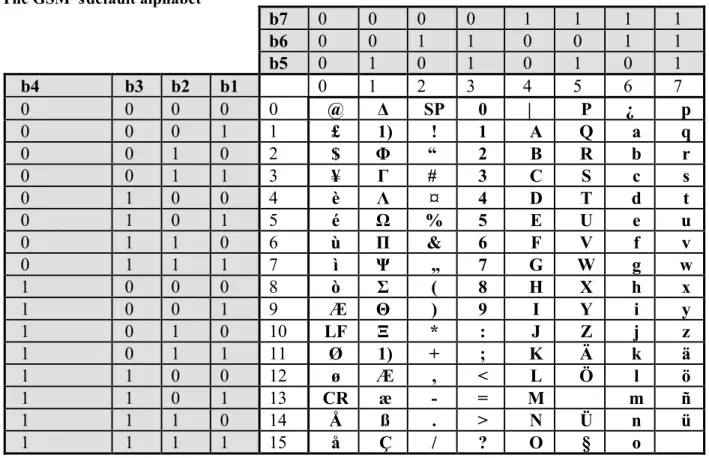
SMS allows transmission of alphanumeric messages having at most 160 characters in length, mapped onto 140 bytes using the default GSM alphabet. Transmission of short messages is based on the store-and – forward concept i.e. a message is not sent directly from one user to another; instead, messages are stored on a SC and they are forwarded to their destination only when the receiving MS is attached to the network. This is one of the major differences between SMS and classical paging: whereas paging needs active recipients, for the SMS service messages can be stored for a given period (even for several weeks/months) on the SC.
The transport of messages, done through out of band signaling channels (SDCCH/ SACCH), allows simultaneous SMS and data/voice communications. An MS is therefore capable of receiving/submitting SMSs to the wireless network at any time, irrespective if is involved or not in an ongoing data/voice call.
The SMS service, as defined by the GSM/DCS/PCS specifications, provides also confirmation of message delivery; using this facility a user can be notified on successful /unsuccessful delivery of the message it forwarded previously to an SC. SMS concatenation is another feature for GSM/DCS/PCS specifications; using this feature more than 160 characters can be send.
Conceptually for SMS two distinct types of services exist in GSM: - point- to- point service – dedicated service involving two parties
- cell broadcastservice– a broadcasting service used for sending information from the network to all the users from one cell or a service area (depending on the type of information sent) -CBS
The message format and delivery modality depends on the previous types of messages. The point –to- point service can be further divided onto:
- Short Message Service Mobile Terminated (SMS-MT) – the capability of a GSM system to deliver a message from a SC to one MS, provide a delivery report indication the success/failure of the delivery and to ensure specific mechanisms for later delivery in case of failure
- Short Message Service Mobile Originated (SMS-MO) – the capability of a GSM system to transfer a message submitted by one MS to a SME via a SC and to provide mechanisms for delivery /failure reports indication the success/failure of the delivery and to ensure specific mechanisms for later The message format is different for SMS-MT and SMS-MO.
Submission and reception of short messages is made available on the mobile phone itself and on remote equipment by using AT commands through an asynchronous serial interface. Short messages emission and reception can be done in:
- text mode(unsupported on most phones) - PDU (protocol description unit) mode
In text mode messages transferred through the serial interface are packed onto characters using some predefined alphabets.
In PDU mode the transfer between remote equipment and the mobile phone is done by packing data onto a binary string, using a hexadecimal representation. Encoding and decoding of the binary stream is done by upper layer application software. PDU mode allows implementation of particular encoding schemes; for example a user is allowed to use an encoding scheme based on a lower number of bits/character (n) than 7 (the number of bits/character of the GSM default alphabet). Using x bits/character a the maximum number of characters/SMS will grow from 160 to 160*7/x. For example using a BCD code (n=6 bits/character) a SMS will contain up to 186 characters.
.1.3 The GSM‟s default alphabet
b7
0
0
0
0
1
1
1
1
b6
0
0
1
1
0
0
1
1
b5
0
1
0
1
0
1
0
1
b4
b3 b2
b1
0
1
2
3
4
5
6
7
0
0
0
0
0
@
Δ
SP
0
|
P
¿
p
0
0
0
1
1
£
1)
!
1
A
Q
a
q
0
0
1
0
2
$
Φ
“
2
B
R
b
r
0
0
1
1
3
¥
Г
#
3
C
S
c
s
0
1
0
0
4
è
Λ
¤
4
D
T
d
t
0
1
0
1
5
é
Ω
%
5
E
U
e
u
0
1
1
0
6
ù
Π
&
6
F
V
f
v
0
1
1
1
7
ì
Ψ
„
7
G
W
g
w
1
0
0
0
8
ò
Σ
(
8
H
X
h
x
1
0
0
1
9
Æ
Θ
)
9
I
Y
i
y
1
0
1
0
10
LF
Ξ
*
:
J
Z
j
z
1
0
1
1
11
Ø
1)
+
;
K
Ä
k
ä
1
1
0
0
12
ø
Æ
,
<
L
Ö
l
ö
1
1
0
1
13
CR
æ
-
=
M
m
ñ
1
1
1
0
14
Å
ß
.
>
N
Ü
n
ü
1
1
1
1
15
å
Ç
/
?
O
§
o
.1.4 AT commands for retrieving/submitting short messages and setting SMS parameters from remote equipment
As mentioned before, even if the SMS service is completely specified for MSs including TE facilities, remote sending/receiving of SMS’s is allowed through AT commands. SMS related AT commands are specified in the GSM 07.05 specification[2]. The most important commands are summarized on the table bellow:
Command Description Responses Remarks
AT+ CSCA=<sca>,[<tosca>] Sets the SC number
for SMS-MO OK <sca><tosca> – MSIDSN for SC - type of address for SC 161- national format, 145 international format
Ex: AT+CSS =”+40722004000” The address is permanently valid. Command can be ignored if the SC address stored on SIM is used. Current SC address can be found with AT+CSCA? Read command. As an alternative to AT+CSCA <sca> can be sent in front of a short message in PDU mode AT + CMGF=mode Sets message format OK If mode =0 PDU mode will be
used for mode=1 text mode is set. The available modes can be checked with AT+CMGF=? test command
AT + CSMS=<service> Selection SMS types (CBS, SMS-MO, SMS-MT)
+CSMS: mt, mo, bm
OK servicecommands =0 phase 2 SMS AT service =1 phase 2+ SMS AT commands mt – 0 MO not supported mt – 1 MO supported mo – 0 MT not supported mo– 1 MT supported
bm – 0 broadcast messages not supported
bm – 1 broadcast messages supported
AT+CSMS? – shows current settings
AT+CPMS=<mem1>,
<mem2>, <mem3> Selection of storage memory for reading/deleting <mem1> writing/sending <mem2> receiving <mem3> +CPMS: <used1>, <total1>, <used2>, <total2>, <used3>, <total3> OK
<mem1> =<mem2> =<mem3> =“SM”
is commonly the option implemented by manufacturers Other values: “ME”, “TL”- template message store
AT+CPMS? displays current settings and and AT+CPMS=? displays possible values
AT +
CNMI=[<mode>[,<mt>[,<bm >[,<ds>]]]]
Selection of the procedure used for indicating to DTE the reception of a message (new SMS or status message) from the network
+CNMI: (list of supported <mode>s),(list of supported<mt>s), (list of supported <bm>s),(list of supported <ds>s),(list of
<mode> most common values are: 2 – indications are sent to DTE only after an ongoing data call has ended
3 – indications are sent to DTE only during ongoing data calls
<mt> - controls how routing of delivered messages to DTE is
supported <bfr>s)
OK performed- mt=1 only the storage place and the index for a new message are indicated to DTE, mt=2 – new message indication includes all above information and some extended information (time stamp, MSIDSN of the originator etc, length etc)
<bm> - sets rules for storage of received broadcast messages; if 0 no CBS messages are routed to DTE
<ds>- sets rules for status
messages routing to DTE (if set to 1 MS reports to DTE if a message was successfully submitted to the network)
<bfr> -
Ex: AT +CNMI=2,2,0,1 allows indications to be passed from DTE to DCE only after eventual ongoing data calls have ended, supplementary information is included in the indication and no new CBS indications is sent to DTE
AT + CGMR=<index> Allows reading of a message stored at <index > in the memory selected by +CPMS command In PDU mode: +GMGR:<stat>,,<le ngth><CR><LF> <pdu>><CR><LF> OK
<stat> - status of the message 0-unread, 1 read message, 2 –stored unread message, 3-stored sent message
<length> - message size in octets (only for PDU mode) integer
<pdu> binary stream encoded short message
AT + CGMR=? – shows if commands in supported AT+ CMSS=<index>[,<da>
[,<toda>]] Send message form storage memory selected by +CPMS command +CMSS: <mr> <mr> is an auto indexing value OK
<index> - location of the stored message
<da> - destination address
<toda>-type of address (similar to
tosca (AT+CSCA)
AT+CMGS= <length> <CR>
PDU message <ctrl-Z / ESC >
Sends message in
PDU mode +CMGS: <mr> <mr> is an auto indexing value OK
<length > - size in octets of the message to be sent
PDU- hexadecimal string
Ctrl-z character code is inserted of the PDU
ESC is used to abort the command AT+CMGW= <length>
[,<stat>] <CR>
PDU message <ctrl-z/ESC>
Stores a message in
the memory +CMGW: <index> OK Same meaning as for AT + CGMW <stat> -same as for AT +CMGR AT +CMGD=<index> Delete message OK Delete message from memory
storage place referred by <index> AT + CMGL=<stat> List messages from
memory storage with the status corresponding to <stat> +CMGL: <index>,<stat>, ,<le ngth>,<pdu><CR>< LF> [+CMGL:
<stat> - 0 unread messages 1- received read message 2- stored unread messages 3- stored sent messages 4- all messages
<index>,<stat>, ,<le ngth>,<pdu><CR>< LF>
[...]]
AT +CSAS=<profile> Saves settings OK Saves the address of the SC and other parameters
.1.5 Formats for SMS-MT and SMS-MO in PDU mode
The PDU message format for the SMS-MT and SMS-MO services are shown on Fig.2 and 3:
SCA PDU type OA PID DCS SCTS UDL UD
1-10
octets 1 octet 2-12 octets 1 octet 1 octet 7octets 1 octet 0-140 octets
Fig.2 SMS-MT format. SCA- Service Centre Address; PDU-Protocol Data Unit;
OA-Originator Address ; PID-Protocol Identifier; DCS-Data Coding scheme ; SCTS- Service centre time stamp ; UDL- user data length ; UD- user data
SCA PDU type MR DA PID DCS VP UDL UD
1-10
octets 1 octet 1 octet 2-12 octets 1 octet 1 octet octets 1/7 1 octet 0-140 octets
Fig.3 SMS-MO format. SCA- Service Centre Address; PDU-Protocol Data Unit;
OA-Originator Address ; PID-Protocol Identifier; DCS-Data Coding scheme ; SCTS- Service centre time stamp ; UDL- user data length ; UD- user data
.1.6 Description/encoding of parameters
SCSA –Service Centre Address – telephone number of SC
The format of SCSA is the following:
length number type BCD digits
1 octet 1 octet 0-8 octets
length - the number of octets required for SC number plus one octet( number type). Typical value 7. If length=”00” the SCSA stored on SIM is used and the other fields are ignored.
number type – hexadecimal string encoding national numbering formats 129=81H and international number formats 145=91H
BCD digits – used for representing the SC actual number; one octet includes 2 swapped BCD digits; encoding is done in the following manner:
octet 1 octet 2 … last octet
digit2 | digit1 digit 4|digit 3 … Last digit/ or FH | Last digit/or 0
Example: The +40744946000 (an Orange Romania SC number) is encoded as 07 91 0447946400F0 PDU – Protocol Data Unit Type
For SMS-MT most important information included in this octet is:
- Reply path – Bit7=0 if not set, Bit7=1 is set. The reply path indicates that the sender is willing to pay
- Status report indication – (Bit5) – is set by SC - a value of 1 means that a status report will be
returned to the SME and will not be sent if 0. Successful reception can be thus indicated to the originator
- More messages to send –(Bit2) – is also set by SC and if 0 more messages are to be sent to the MS
- Message type indicator – Bits 1 and 0 – used for indicating the type of message. The values are
always 00 for SMS-MT
- Bits 4 and 3 are not used and they are set to 0
A typical octet for the SMS-MT message has the following structure (04H):
Bit7 Bit6 Bit5 Bit4 Bit3 Bit2 Bit1 Bit0
0 0 0 0 0 1 0 0
For SMS-MO most important information included in this octet is:
- Reply path - same as before – if the sender sets this bits it agrees to pay for the response
- Status report request – (Bit5) –used for requesting delivery reports (0 if reports are not desired and 1
if a delivery report is to be returned to the MS)
- Validity period format –(Bits 4 and 3) – indicates if a validity period is included in the message and
if present how it must be interpreted; most common values 00- no validity period, 10 – 1 octet representation
- Message type indicator – Bits 1 and 0 – used for indicating the type of message. The values are
always 01 for SMS-M0
A typical octet for the SMS-MO message has the following structure (11H):
Bit7 Bit6 Bit5 Bit4 Bit3 Bit2 Bit1 Bit0
0 0 0 1 0 0 0 1
OA/DA – Originator/Destination Address
Both addresses are having the same format, somewhat similar to SCSA, the single differences being the length of the “BCD digits field” which might be in this case 10 bits and, respectively, the meaning of the “length” parameter which encodes the number of digits of the phone number.
Example: The + 40744991518 is encoded as 0B 91 0447941915F8. The same number in national format 0744991518 is encoded as: OA 81 7044775181
MR – Message refference
This one octet information shows how a submitted message is reference. A value of “0H” allows the MS to manage the reference number.
SMS-MT no reply path no status
report
no more messages for MS stored at SC
SMS-MO no reply path no status
report
one octet representation for the validity
PID – Protocol identifier
PID is used to instruct the SC in which format/protocol the short message should be delivered. The originator of the message is allowed to set this field. The possible values are:
00H- PDU is to be treated as a short message; 01H – PDU is to be treated as a telex; 02H- PDU is to be treated as a group 3 fax; 03H- PDU is to be treated as a group 4; 04H – PDU is to be treated as a voice call (this implies automatic conversion to speech).
DCS – Data coding scheme
The usage of this octet is twofold; it can indicate the coding scheme use for the user data (UD) and the message class:
Bit7 Bit6 Bit5 Bit4 Bit3 Bit2 Bit1 Bit0
0 0 b5 b4 b3 b2 b1 b0
b5 = 0/1 – UD is not compressed / is compressed
b4 =0/1 – b1and b0 are reserved/ b1and b0 are indicating the message class
b3 b2 - are indicating the alphabet being used: 00 –default 7 bit GSM alphabet, 01 - 8 bit (ASCII) – alphabet, 10 – Unicode (16 bit), 11 – reserved combination
b1b0 – 00 – class 0 message, 01 –class 1 message, 10-class 2, 11 –class 3
Example: DCS=00H- indicates the default GSM alphabet, no compression, class 0 message; DCS=04H – 8 bit encoding is used
VP – validity period
Indicates the period after which the SMS expires (message is deleted from SC if not delivered yet). Information is represented using one octet representation or 7 octets representation:
Bit7 Bit6 Bit5 Bit4 Bit3 Bit2 Bit1 Bit0
b7 b6 b5 b4 b3 b2 b1 b0
In the case of one octet representation (most common) the validity period indication is relative, counted from the time when SC receives the message. For N = b7 b6 b5 b4 b3 b2 b1 b0 conversion is done as follows:
- if N between 0-143 - VP=(N+1)*5 minutes;
- if N between 144-167-VP=12h+(N-143)*30 minutes - if N between 168 -196 -VP=(N-166) *1 day
- if N between 197 – 255 – VP= (N-192)*1 week Example: a VP of 5 days is encoded as ABH
Remark: VP is optional; the PDU –type octet indicates if it missing for SMS-MO
In absolute representation the validity period is represented on 7 octets in a Year/ Month/ Day/ Hour/ Minute /Second/ Time zone format, similar to the format of SCTS
SCTS – Service Centre Time Stamp
Is used by the SC to inform the MS when it received a short message. The following format is used: Octet 1 Octet 2 Octet 3 Octet 4 Octet 5 Octet 6 Octet 7
Y2 | Y1 Mo2 | Mo1 D2 |D1 H2|H1 Mi2 | Mi1 S2|S1 TZ2 |TZ1
Example: An SCTS value encoded as 50 01 72 01 03 00 80 means that the SC received the SMS-MT message for delivering at: 27 October 2005 10h30min00sec GMT+2h (Romanian time TZ1TZ2x15 min=2h)
UDL – user data lenght
Represent the length of the UD field in integer representation. A value of 0A will indicate a UD field encoding 10 characters.
UD – user data
Encodes the actual content of the message using the alphabet specified by the DCS. For point to point SMS the mostused alphabet since it allows to pack 160 characters in 140 octets. 7 bit data if converted to 8 bit format as shown below.
Let b11 b12 b13 b14 b15 b16 b17 denote the first character, b21 b22 b23 b24 b25 b26 b27 the second, b31 b32 b33 b34
b35 b36 b37 and so on… The most significant bit is –for each character- the 7th bit. Packing of 9 characters is
shown in Fig.4.
It can be easily noticed that when packing 8 characters only 7 octets are used i.e 140 octets can be used to carry 160 7 bit characters. If packing is not exact remaining fields are completed with 0s.
b21 b17 b16 b15 b14 b13 b12 b11 b32 b31 b27 b26 b25 b24 b23 b22 b43 b42 b41 b37 b36 b35 b34 b33 b54 b53 b52 b51 b47 b46 b45 b44 b65 b64 b63 b62 b61 b57 b56 b55 b76 b75 b74 b73 b72 b71 b67 b66 b87 b86 b85 b84 b83 b82 b81 b77 0 b97 b96 b95 b94 b93 b92 b91
Fig.2 Packing 7 bit data onto octets
Example: Using the GSM 7 bit alphabetthe message - TEST 1- will be encoded as follows: TEST1 --> 101010010001011010011101010011111110110001 1 1 0 1 0 1 0 0 1 1 1 0 0 0 1 0 1 0 0 1 0 1 0 0 1 1 1 1 1 0 1 0 1 0 0 0 1 1 1 1 0 0 0 0 0 0 0 1
Reading row wise and concatenating the converted values the following hexadecimal UD is obtained: D4E294FA8F01
.1.7 Pre-assignments
1. Which is the maximum number of characters that can be sent using SMS?
2. What advantages provides the store-and-forward concept behind the SMS service?
3. If a user is involved in an active communication will be able to receive/send SMSs? Justify your answer. 4. Which is the difference between point-to-point SMS and CBS?
5. When a user sends a short message it uses the SMS-MT or SMS-MO?
5. Which are the advantages of PDU mode over text mode for point-to-point messages? 6. Which is the purpose of using SMS related AT commands?
9. Which are the AT commands used for retrieving/sending a message on DTE? 10. How SMS PDU mode can be set up on the MS?
13. Which are the differences between SMS-MO and SMS-MT message formats? Describe the functionality of the fields that are different.
14. Is GSM providing the possibility to reply to a message free of charge? 15. Encode onto the correct format the following values:
Service centre address: +40722006000 VP: 4 days
UD: SIM
.1.7 Laboratory platform
Two distinct applications are available on the web site and should be downloadedon the following folders: - “D:\CM_2012\L2\GSM_7bit_alphabet”
- “D:\CM_2012\L2\AT_SMS_support”
.1.8 GSM_7bit_alphabet
The first application allows study of conversions between hexadecimal/text strings and the GSM format constructed using the GSM default alphabet. The Microsoft Visual Basic project includes a form frmMain and a module Module1.bas containing contains some predefined functions. The user interface frmMain is shown on Fig.3:
Fig.3 FrmMain (D:\CM_2012\L2\GSM_7bit_alphabet)
txtGSMInput txtBin txtGSM txtAscii Command1 Command2 txtInputAscii txtOutputGSM
Text boxes are to be used for inputting/outputting data in various formats. The two command buttons are used for performing the conversions:
- GSM (representing in hexadecimal a possible UD field) to ASCII (text) (Command1) - ASCII (text) to GSM (possible UD field) (Command2)
The application can be used in order to properly encode/decode the UD field for sending/retrieving SMSs in PDU mode.
.1.9 Assignments
1
. Identify how encoding and decoding of the UD field is done for the predefined value and for an arbitrary ASCII input text message2. Which is the length of the hexadecimal string? Which would be the length of the sequence if a 8 bit alphabet would be used?
3. Input some arbitrary text in txtInputAscii and write down the resulting UD field
5. Check the conversion by copying the converted value from txtOutputGSM to txtGSMInput
.1.10
A
T_ SMS_Suport
The second application allows sending/receiving/inspecting values of short messages using AT commands. The main form is represented in Fig.4.
The following VB structure is used to retrieve data for a given SMS (using data fields similar to those listed in Fig.2 Public Type SMS_MT SMS_PDUFrame As String SC_length As String SC_typeofadress As String SC_adress As String PDU_type As String OA As String Sender_number As String PID As String DCS As String SCTS As String UDL As String UD As String length As Integer End Type
Two variables are also defined defined for handling data: Public PDU_index As Integer –defined at module level Dim message As SMS_MT- defined at form level
Fig.4 FrmMain (D:\CM_2012\L2\AT commands for SMS applications)
2.11.11 Assignments
1. Run the program. Write down the UD for the SMS stored at index 1 on the ME. 3. Explain the various fields for the PDU payload information
4. Decode the UD field using the GSM_7bit_alphabet application. Write down the result. 5. Put a command button on the form. Name it “cmdVocal”
6. Add a vocal synthesis component to the VB project. Surf to Project->Components->Microsoft Direct Text to Speech. Select the component. Drag the
icon on the form and set its name to
spkSpeak
7. Add the following code to the cmdVocal button: spkSpeak.Speak txtInfo.Text
8. Run the program. Paste the code find out in step 4 in txtInfo 9. Click on spkSpeak. If everything is ok you should hear the result. 10. Place a command button on the form. Name it cmdSend
11. The following sequence can be used to send an SMS. Which are its parameters (SMS-MO message)? WriteIR_serial ("AT+CMGF=0" & vbCr)
delay(2)
DateIR = "AT+CMGS=20” & vbCr WriteIR_serial (DateIR)
DateIR= “0011000B91xxxxxxxxxxxx0000AA06D4E294FA8F01” WriteIR (DateIR & Chr(26))
delay(10)
txtInfo.Text=ReadIR_Serial
12. Replace the sequence figured with xxxx…xxx with the formatted OA address of another phone used as hardware support
13. Paste the complete code onto the click event of the cmdSend button. Click the send button
14. Based on the description of the code associated with the cmdRead button write a routine that will automatically format a SMS-MO
15. SMS dictation can be also enabled using speech recognition engines. Add a new component to the project: surf to Project->Components->Microsoft Direct Speech Recognition. Select the component.
16. Drag its icon onto the form and select its name to dsRecog. Paste the following code onto the Form_Load procedure:
totaldata = "[Grammar]" & vbCrLf & _ "langid = 1033" & vbCrLf & _ "type=cfg" & vbCrLf & _ "[<Start>]" & vbCrLf & _ "<start>=Test" & vbCrLf & _ "<start>=One" & vbCrLf & _ "<start>=Mobile" & vbCrLf
dsRecog.GrammarFromString (totaldata) dsRecog.Activate
17. Paste the following code to the PhraseFinish event: txtInfo.text=txtInfo.text & Phrase
References
[1] 3GPP TS 07.07 AT command set for GSM Mobile Equipment (ME) (Release 1998); http://www.3gpp.org
[2] S. Redl, N. Weber, M. Oliphant – GSM and Personal Communications Handbook, Artech House Publishers, 1998
[3] GSM 03.40 –Technical realization of the Short Message Service