INFORMATION SCIENCe'S LI_,qARY
MO-:F.Yi'T FI:!.D, CLLIF.
MULTICAST
ROUTING_'_::tF
HIERARCHICAL
DATA*
Nachum
Shacham
SRI
International
NASA-C R- Z0
s _9
Information,
Telecommunications,
and
Automation
Division
Menlo
Park,
CA
94025
/)_5/2/J/_//
ITAD-8600-CP-91-40
(. : . .z
ABSTRACT
The issue of multicast of broadband, real-time data in a heterogeneous environ-ment, in which the data recipients differ in their reception abilities, is considered. Traditional multicast schemes, which are designed to deliver all the source data to all recipients, offer limited performance in such an environment, since they must either force the source to overcompress its signal or restrict the destination population to those who can receive the full signal. We present an approach for resolving this issue by combining hierarchical source coding techniques, which allow recipients to trade off reception bandwidth for signal quality, and sophisticated routing algorithms that deliver to each destination the maximum possible signal quality. The field of hierar-chical coding is briefly surveyed and new multicast routing algorithms are presented. The algorithms are compared in terms of network utilization efficiency, lengths of paths, and the required mechanisms for forwarding packets on the resulting paths.
h
*This work was supported by the Defense Advanced Research Projects Agency (DARPA) under contract NAS2-13181 and by SRI Independent Research and Development funds.
1
INTRODUCTION
Distributing information to multiple recipients, also known as multicast, is an impor-tant service that broadband networks will be required to provide for many applica-tions, such as multimedia teleconferencing, remote collaboration, distributed database updating, and distribution of weather and stock market information [1]. However, de-spite the recognized need for multicast service, surprisingly little has been developed to provide it. At the physical level, high-speed switch fabrics were designed that can replicate an incoming packet and deliver it to multiple output ports [2, 3]. At the network layer, a few algorithms for computing a multicast tree from a source to multi-ple destinations and protocols for datagram multicasting were reported [4]. Limited versions of the datagram multicast have been recently implemented and tested on the Tl-based DARTnet. At the transport level, most of the effort thus far has been in the theoretical design of mechanisms for reliable transmission to multiple recipients and in the analysis of their properties [5, 6, 7]. Some of these ideas were used in the design of the XTP protocol [8], which has a multicast mode. Other popular protocols, most notably TCP [9], do not provide multicast service.
The inefficiency of existing multicast protocols when operating in a heterogeneous environment stems from their basic design assumption that all recipients must receive all the information emitted by the source. However, this may not always be feasi-ble or even desirable, especially when the multicast information is broadband, which requires wide channels and capable user-terminal equipment. The users in this het-erogeneous environment are expected to differ greatly in the end devices they employ
and the network-access bandwidth available to them. Thus, when a source distributes a broadband signal to multiple users, not all of them are willing or capable of receiv-ing the complete signal. Many users can or are content to receive only a subset of the information contained in the multicast signal. An example for such a scenario is video distribution. Some users with wideband access, high-resolution displays, and power-ful processors can receive and process the complete high-resolution color video signal. Others_ with simpler displays or lower-bandwidth access that makes them capable of receiving only part of the signal_ may prefer to receive, say, only black-and-white, low-resolution video rather than no video at all. Similarly, in voice communication, some users may settle for low-rate synthetic speech without speaker recognition when they cannot receive the complete digital speech signal.
T2)
Source
©
®
[
T4
T3
Figure 1: Distribution of a Hierarchically Encoded Signal in a Heteroge-neous Network and Recipient Environment
Moreover, users may still differ in the signal levels they receive, even if they
have similar access bandwidth and terminals. In multimedia teleconferencing, for example, users who send and receive multiple streams representing the various media may not be able to obtain the full bandwidth needed to communicate all these media simultaneously. Consequently, individual users must choose signals they want to emphasize, and these choices are likely to change with time and from user to user, reflecting an individual user focusing on different media at different times.
Multicast in a heterogeneous environment is illustrated in Figure 1, where the source generates a broadband signal that has to be delivered to four terminals. Two of the terminals (T1 and T2) can accept and display the complete broadband signal (say, high-resolution, full-motion video), while the others (T3 and T4) can receive only a limited version of the signal, say black-and-white video. The network comprises broadband (thick lines) and narrowband (thin lines) links, which in our example have bandwidth sufficient to deliver the full signal and its limited version, respectively. As can be seen from Figure 1, only T2 has both the capability and the broadband path needed to receive the full signal. Terminal T1 is constrained to the limited version of the signal by link (A, 3), whereas T3, though it has a broadband path, can accept only a limited signal. Terminal T4 is limited by both the network and its own capability.
Using a datagram multicast routing protocol in combination with a multicast transport protocol, which attempt to deliver the whole traffic stream to all the re-cipients, results in great inefficiencies and even a failure of a multicast session in a heterogeneous environment. The source, forced to emit traffic at a rate dictated by the least capable recipient [8], faces a serious dilemma: it can over compress (and hence distort) the signal to accommodate the least capable users, thereby penalizing the more capable recipients who end up receiving signal quality much lower than they desire and can accept. Alternatively, the source may exclude the more limited desti-nations that cannot receive its full signal, thereby reducing the number of recipients that can participate in the session. Furthermore, both alternatives require the source to adapt each new session, or even in mid-session, to the needs and constraints set by both the network and the set of multicast recipients. Even small changes in either of these, such as the addition of a new destination with limited capacity or a link failure, may require the source to drastically change its mode of operation, thereby causing the recipients to experience fluctuating received signal quality. Having to adapt to time-varying signal quality forces the recipients to employ more complex software than the would use under constant or predictable received quality.
Since heterogeneous environments are expected to be common in broadband net-works, the aforementioned features of existing protocols greatly inhibit information distribution. Furthermore, since recipient population may vary from session to ses-sion, and even during a session, the rate of traffic delivery is expected to fluctuate, resulting in an inconsistent service level. In this paper we outline an approach for multicast in a heterogeneous environment, which is responsive to source and recipi-ents' traffic demands, and provides stable service and efficient utilization of network resources. In the framework of the example depicted in Figure 1, users' and networks' constraints dictate that T2 receive the full signal, whereas T1, T3, and T4 only its limited version. Furthermore, efficient network utilization requires that link (B, C)
carries only the signal's narrowband version, since that link does not lead to any broadband recipient.
In this paper we present an approach for providing such a service by integrating:
1. Hierarchical source coding, in which different subsets of the source's stream represent the signal at corresponding quality level. Such coding allows users
2. Enhanced multicast routing protocols that take into consideration the recipi-ents' bandwidth constraints and available link capacities.
The combination of these two areas results in several advantages. Firstly, having the source emit to the networks a single (full) representation of its signal has the effect of reducing congestion levels in the vicinity of the source. Moreover, the source has to perform much less processing, and the variations in user population axe transparent to the source, thereby increasing the session's stability. Secondly, incorporating the network and user's constraints in the route computation and data replication, leads to better utilization of network resources.
In the following we discuss these two aspects of hierarchical multicast. Section 2 provides a brief overview of existing hierarchical coding techniques, which can be used for multicast in heterogeneous environment. The networking aspects of the problem, which are much less developed than source coding, are the main focus of this paper. In Section 3 we present an algorithm for computing the bandwidth available to all destinations and several approaches for using this information to obtain the required sets of routes. In Section 4 we discuss methods for forwarding packets along the sets of routes so obtained, and Section 5 contains some concluding remarks.
2
HIERARCHICAL
CODING
Hierarchical coding is a term for a family of signal-representation techniques, in which the source information, most commonly a digital, real-time signal, is partitioned into substreams, each of which represents a well-defined portion of the signal. The sub-streams, also known as layers, are so constructed that Substream 1 (the lowest layer) carries the elements that are essential for reconstruction of the signal by the receiver, albeit at low quality. For example, Layer 1 may contain timing, synchronization, and frame information, as well as the bits required to display a black-and-white video. Alternatively, Layer 1 may contain the odd-numbered frames, so that it allows a re-cipient to reconstruct the video at the original resolution but at half the frame rate, resulting in a less-smooth video. Layer i (i > 1) contains information that improves the reception quality over that obtained by Layers 1, 2,..., i - 1.
Extensive research has been conducted on hierarchical encoding, which is also known as pyramidal, layered, or subband encoding, especially for speech and video signals. The first hierarchical coding scheme was designed for speech transport over packet-switching integrated networks [10]. In this technique, the lowest layer contains the most significant bits of the digital representation of the speech signal, and Layer
i contains bits of lower significance than Layer i - 1, but of higher significance than those in Layer i + 1. In this case, Layer i improves the signal quality at the receiver, if and only if all layers below it are received as well.
Hierarchical speech coding can also be based on recently developed speech com-pression algorithms. In particular, the following algorithms are suitable for integration into a pyramidal encoding algorithm:
LPC10 [11] 2.4 kbps CELP [12] 4.8 kbps
RELP [13] 9.6 kbps
Generates 10 LPC filter coefficients
Uses the same filter coefficients and adds filter excitation information (from a codebook) Uses the speech synthesized above and adds an encoded representation of the error ("residual").
The integration of these three algorithms into a hierarchical encoding method is made possible by the fact that each algorithm is based upon a 10-order linear predictive coder (LPC). There are small differences in the algorithms, such as the frame interval at which the LPC coefficients are updated, and the interval at which the excitation signal is updated; however, these can be reconciled by deferring to the lower rate coding when there are differences. This would tend to produce the best possible quality for the low rate codes, while sacrificing some quality at the higher rates.
While some of the hierarchical speech coding techniques are also applicable for video, several other hierarchical coding techniques have been developed that exploit the unique features of the video signal, which comprises a sequence of frames, with intraframe spatial correlation and interframe temporal correlation. We describe below one of the numerous hierarchical coding schemes that can be found in the literature, with emphasis on features that impact signal transmission over a network.
In this example, a basic video encoding technique called conditional replenishment is utilized to generate a variable bit rate (VBR) stream, based on which a receiver
is sensitiveto bit errors and data loss,implying that quality may be severelyaffected
when sucha stream is transmitted overa packet-switchingnetwork. To overcomethis
problem, the video stream is partitioned into two substreams:
1. The first layer contains essential video information such as synchronization
pulses and addresschanges,as well as basic video data. Receiving this part
alone allows the receiver to obtain a low-quality video signal. Sincethis
infor-mation is vital, its integrity is guaranteedby a reliable transfer protocol.
2. The secondlayer contains "add-on" information, which improvesthe quality of
the receivedvideo. This information is sent over the network over shared links,
which results in packet loss. However, the video signal is separatedin such a
way that lossesin the secondpart do not affect the quality of the first part.
This schemeis implemented with 110- 120kbps for the complete video signal,
of which 24 kbps are devoted to the first layer. When both parts of the signal suffer
no losses,the picture quality is dependent only on the coding parameters of the
secondpart. As the lossrate of the secondpart increases,the video exhibits graceful
degradationin quality. Even at 100%packet lossrate for the secondlayer, the signal
exhibits reasonablequality, despite being somewhatimpaired by smearing and block
structure distortion.
It is interesting to note that the emergingstandard for video compression,named
MPEG [15], also generates a hierarchically structured signal. Every eighth frame is a reference frame containing the complete set of parameters needed for frame recon-struction at the receiver, whereas other frames (the interframes) carry only informa-tion about changes from these reference frames. Receiving only the reference frames (which constitute the lowest layer) results in a low-quality video, which is improved as more interframes are received.
As mentioned above, much simpler hierarchical video representations can be de-vised. For example, the lowest layer may comprise the odd-numbered frames, whereas the second layer comprises the even-numbered frames. Alternatively, the lowest layer can contain the black-and-white video components, while the color information is embedded in higher layers.
As this discussion demonstrates, hierarchical coding techniques for real-time traf-fic already exist. Moreover, hierarchical representation is not just for real-time traffic.
Weather information and stockmarket updates are
just two examples for traffic typesthat can be received at different levels of detail based on users' constraints and inter-est.
There are, however, still some design and implementation issues to be addressed. Most notably, one should devise the best methods to partition a signal into layers from signal quality and error performance points of view and methods for layered-based packetization. These issues, however, are beyond the scope of this paper.
3
MULTICAST
ROUTING
OF
HIERARCHICALLY
EN-CODED
DATA
Having encoded its signal hierarchically, the source packetizes the signal so that each packet carries bits from a single layer. The source emits these packets to the network, which has the responsibility of transferring them to the multicast destinations. To
that end the network computes a set of routes from the source to all destinations and forwards the packets along those routes. Since the source emits a single copy of each
packet, the forwarding task also includes packet replication.
As discussed above, it is expected that, due to variations in congestion, not all destinations are reachable by paths that have sufficient bandwidth to carry the full signal. And even when such paths are available, terminal constraints may prevent certain destinations from receiving the complete set of signal-hierarchy layers.
Under these circumstances, computing routes for hierarchical multicast is more complex than in traditional datagram multicast routing. The latter aims at distribut-ing all datagrams to all destinations, and it usually assumes that all network links have sufficient capacity for carrying all datagrams. Such multicast routing therefore amounts to finding a tree that spans all destinations and has some optimality prop-erties, such as minimum total cost or shortest path to each destination. For example, when a unit link cost is assumed, that minimum spanning cost tree amounts to the smallest number of links in the tree, and shortest path is translated into minimum
hop count on each path.
In the case under study here, we are interested in finding paths that can accom-modate traffic streams with non-negligible throughput compared to link capacities,
so that each destination receivesthe best signal level possible. The set of routes
should be efficient, from the standpoint of both network utilization and end-user
performance. In particular, we define the following routing objectives:
1. Each destination receivesthe number of layers it requestsor the maximum
number the network bandwidth allows, whicheveris smaller.
2. The network is efficiently utilized, so that no link carries more traffic than is
actually delivered to the destinations on the paths of which that link is a part.
3. The paths are optimal with respect to user performanceor cost.
For example,if a delay is a critical factor, the shortest path that can deliver the traffic to a given destination is used.
We now proceed to describe how these requirements can be fulfilled. We be-gin by describing an algorithm for computing maximum bandwidth available to all destinations. Subsequently, routes with these capacities are determined.
3.1
Network
model
In the model we use, the network is represented by a graph G = (V, E), where V and E are the sets of nodes and links, respectively. Each link (i,j) E E is characterized by its available capacity b(i,j). The available capacity of the path {il, i2,.., i,_} is defined
as minj{bq_,ii+,)}, 1 _< j _< n - 1.
To extend the model to also incorporate destination's bandwidth requirements, the graph G is augmented by N links and N nodes, where N is the number of multicast destinations. For each destination d, which is connected to node e of the original graph and requires arrival at rate Wd, a node d and a link (e, d) are added with the link capacity b(_,d) = Wd.
The source's signal is encoded into K-layer hierarchy, where Layer 1 (the lowest layer) represents the basic signal and Layer i (1 < i < K) provides improvement over the quality of the signal constructed from Layers 1, 2,..., i - 1. The ith layer of the hierarchy is assumed to require path bandwidth of Li; thus, to receive the signal at
Level
i, a destination must receive a signal of bandwidth Wi = _=1 Lj. The terminal requirements mentioned above are assumed to match these Wi's.The objective of the multicast routing is to compute the maximum number of signal layers that can be delivered to each destination and to find efficient routes over which such traffic can be delivered.
3.2
Maximum
bandwidth
computation
Given the aforementioned model, we use a Dijkstra-like algorithm to compute the maximum bandwidth to all destinations. The algorithm begins by labeling the source, say Node 1, by Bi = oo, and all other nodes are temporarily labeled by zero, i.e.,
B_ = 0. The label values represent the maximum path capacity from the source to each of the nodes. The algorithm's first step is to assign to all l's neighbor nodes temporary labels according to B_ = b(x,i}. The node with the maximum label value, say Node 2, is assigned a permanent label B2 = B_. The temporary labels of 2's neighbor nodes are then modified according to:
B_ := max{B_,min{B2, b(2,0} } .
That is, the capacity of the path from 1 to i through 2 is the maximum between its previous label and the path capacity through 2. After this temporary labeling, the node with the maximum temporary label is permanently labeled (i.e., converting B_
to Bi). The process repeats itself, where in a typical step the node with the largest temporary label is permanently labeled, and the temporary labels of all its neighbors are accordingly modified. The algorithm stops when the last node of the graph is permanently labeled. It can be shown that a node's permanent label so assigned has a value that equals the maximum path capacities from the source to that node.
It is interesting to note that this algorithm assigns permanent label values in a non-decreasing sequence. Consequently, once the algorithm computes permanent labels for all the multicast destination nodes and those nodes with labels not strictly smaller than the smallest destination label, there is no path through unassigned nodes that can carry enough layers of the signal hierarchy needed for a destination. That is, if it is necessary for all the layers directed to a given destination to be routed on the same path, the algorithm can stop after it assigns the first label strictly smaller than the
smallest destination label. However,if layers are allowed to be carried over different
paths, the algorithm stops onceit assignsthe first permanent label
Bj < min Li.We now proceed to describe how maximum bandwidth paths are constructed.
3.3
Labeler-based
tree
The simplest way to convert the output of the aforementioned algorithm to a set of maximal bandwidth routes is to use the tree that is defined by the set of links connecting nodes with the nodes through which they acquire their permanent label. This is similar to traditional multicast routing in which a shortest path tree is defined by the labeling order.
From the algorithm description it is clear that this labeler-tree is constructed by first building the subtree that carries the maximum number of layers, then extending it by adding, in stages, lower and lower bandwidth links. Each extension includes only nodes that have not been permanently labeled thus far, thereby retaining the tree structure. A path in this tree thus has the property that the link bandwidth is a non-decreasing function of the distance in hops from the source. Thus, each path is guaranteed to have sufficient bandwidth to the destination to which it leads.
There are two issues with this scheme:
• It does not tell us how many signal layers each link should carry.
• The paths it generates are not necessarily the shortest among those with the same maximum bandwidth.
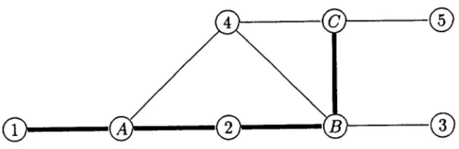
To demonstrate the first issue, consider Figure 2, in which Node 1 is the source and Nodes 2, 3, 4, 5 are the destinations. Suppose that the source's signal hierarchy consists of two layers: the lowest layer requires 1 unit of link capacity, while the full signal requires 3 units. In this figure thick (thin) lines represent link capacity of 3 (1). The tree constructed by this algorithm contains all the thick links plus links (B, 3) and (C, 5). Node 4 may be connected to either A, B, or C. It is clear that Node 5 can receive only the lowest layer. Notice, however, that link (B, C) that appears in the tree with capacity 3 need not carry the full signal since it does not lead to
a destination that can receive it. Therefore, it will be a waste of bandwidth if that link carries the full signal. However, the algorithm as described above does not tell us when to filter the source's signal in order to get more efficient utilization of link
capacities. To rectify this deficiency, we modify the algorithm as described below.
The second issue, namely the non-shortest paths, is due to the fact that a node's permanent label is assigned regardless of the distance from the source of the neigh-boring node. For example, Node 4 is equally likely to be labeled by A, B, or C. We discuss how to select shorter paths later in the paper, but first we consider the issue of efficient link utilization.
3.4
Enhancements
of the
labeler-tree
To increase the link-utilization efficiency of the labeler-based maximum bandwidth tree, we begin with the leaves and progress toward the source in the following manner: First, select a destination that has an assigned bandwidth lower than the maximum, (say, Node 3 in Figure 2). Follow its tree path to the source and reduce any link bandwidth to the destination bandwidth. Continue this operation until the path meets a node with an outgoing link of higher bandwidth than that of the selected destination (Node B). At that point, select another destination (say, Node 5) and continue the procedure (this time reducing the bandwidth assignment of (B,C)).
Leaves that are not multicast destinations can be assigned bandwidth requirement of 0 so that the algorithm can handle all tree leaves in a uniform manner. Once all the children of a tree node have been treated in this manner, that node is assigned the largest bandwidth of all of its children (in our example, capacity 1 for Node B) and the bandwidth reduction continues from this node toward the source. The bandwidth reduction algorithm handles each tree link exactly once.
Notice, however, that since the paths are assigned based on maximum bandwidth, this "bandwidth trimming" procedure may cause a tree path to a destination to be longer than other paths to that destination with the same bandwidth. For example, the route through the subtree to Node 5 (1 - A - 2 - B - C - 5) is longer than
(1 - A - 4 - C - 5), and both have the same capacity.
The labeling procedure can be modified to obtain somewhat shorter paths. This is accomplished by selecting for a permanent label, among all nodes with maximum
bandwidth, the node and a labeler that will result in the shortest distance from the source. That is, each node of the set with maximum temporary label, which has more than one potential node through which its permanent label can be assigned, selects the one closest to the source to acquire that label. The temporarily labeled node closest to the source is assigned a permanent label. For example, in Figure 2, the order of labeling is A, 2, B, C (broadband), then 4, 5, 3 are candidates for permanent label. Node 4 is assigned first since it has the shortest path from the source through
A. Then the assignment order is 3, 5.
Although this modification improves the distance to 4, it does not provide the shortest route to 5, since Node C was assigned a permanent label (with distance 4) before Node 4 (distance 2), thereby locking 5 out of a shorter path it has through 4.
3.5
Constructing
an
efficient
tree
in
stages
To rectify this problem, we modify the above algorithm so that it incorporates band-width trimming more often. This can be done by first considering the links with available bandwidth WK, i.e., those that can carry the full signal, and then con-structing a shortest-path spanning tree using only these links. If this spanning tree reaches all destinations of our multicast sessions, the procedure ends with all desti-nations capable of receiving the full signal. Otherwise, the tree must be expanded with links of WK-1 to additional destinations that can receive only K - 1 layers of the source signal. For example, in Figure 2 this first step produces a tree with Nodes 1, A, 2, B, C, and the thick links connecting them.
However, before extending the tree, we observe that the subtree we have already constructed using the links with WK may contain overutilized links. These are the links that do not lead to a destination after the first step; therefore, the path to any destination they may lead to in future steps must contain a lower-bandwidth link, thereby restricting the path's bandwidth below WK. These overutilized links must therefore be eliminated from the highest-bandwidth spanning tree, which is done as follows. We select a tree leaf that is not a multicast destination, and delete the tree
link leading to it. We then consider the reduced tree and repeat the operation until there are no leaves that are not destinations. The resulting tree is the basis for the expansion. In our example, Nodes C and B are not destinations; therefore, links (2, B) and (B,C) are deleted from the tree.
O
®
Figure 2: Multicast Routing with Two Link Types (The source is 1 and the destinations are 2, 3, 4, 5.)
To expand the tree, we first consider all the links with available bandwidth WK,
which are not included in the tree, as having an available bandwidth of WK-1. We join them with the rest of the links with bandwidth WK-1 and expand the spanning tree, so that paths with shortest distance from the source are obtained to all the nodes reachable by this additional set of links. Again, in our example, links (2, B) and (B, C) are now becoming thin links and are used to expand the tree along with the other thin links. We again eliminate the links that do not lead to a destination, and reassess their capacity as WK-2. We continue in this manner until all the multicast destinations are reached.
3.6
Maximum-bandwidth
shortest
paths
The tree expansion procedure described above involves a trade-off. Recall that the input to the first expansion, is the set of links with WK-1 and the WK spanning tree with minimum distance assigned to each of its nodes. In the expansion we either do or do not allow changes in the distances of the first tree. A node of the WK tree may
change its distance when a link of WK-1 completes a cycle. Since we do not want to eliminate the WK links in the first tree (since they provide the broadband path to that node), we may either allow the WK-1 link to be added, thereby closing loops and destroying the tree structure, or we may not allow the inclusion of those links, in which case the resulting paths to the WK-1 nodes may not be the shortest. As an example of such a situation, consider the graph in Figure 2, in which Nodes 2, C
and 5 are the destinations. The path to Node
C is 1 - A - 2 - B - C, on which the complete signal is delivered. When extending the path to Node 5, we face the following situation: using the previous path and extending it by (C, 5) preserves the tree structure. However, the path 1 - A - 4 - C - 5 is shorter yet delivers the same bandwidth to Node 5; therefore it is preferable, but it destroys the tree structure of the paths!Computing these maximum-bandwidth, shortest paths to all destinations is ac-complished through the following steps:
1. Compute a spanning tree using the links that can support the full signal, i.e., those with capacity of at least WK. Eliminate all links that do not lead to multicast destinations.
2. Consider all links of capacity W K as having capacity WK_ 1 and compute a spanning tree using the links with capacities W/_-I. Eliminate all links that do not lead to multicast destinations that were not included in the previous step.
3. The i-th step computes a spanning tree of all links with capacity of at least
Wg-i+l and eliminates all links that do not lead to multicast destinations that were not included in the previous steps.
The maximum-bandwidth, shortest routes are the union of these trees. A node belongs to the first tree in which it is included in the above algorithm.
3.7
Separate
tree
for
each
layer
The previous algorithm results in a union of K spanning trees, the i-th of which has the capacity to carry the first K - i + 1 layers of the signal. That is, each node gets all the signal layers delivered to it on the path on the tree that contains that node. The advantage of this technique is that all the layers to a given node follow the same path, thereby reducing the risk of out-of-order packet arrival. However, as we discuss in the next section, this scheme results in complications in forwarding and somewhat inefficient network utilization.
If weallow different layersof the hierarchy to reacha destination through different
paths, more efficient routes can be established. In this approach,we still compute
Kspanning trees; however, the i-th spanning tree carries only the packets belonging to Layer i, i.e., the i-th tree has capacity of Li rather than Wg-i+l. Also, unlike the previous procedures, here we begin with the lowest layer. The algorithm first uses all links that can carry the lowest layer, i.e., they have capacity of at least L1. It then computes a rain-hop spanning tree and eliminates all links that do not lead to multicast destinations, and reduces the available capacity of the links that belong to this tree by L1.
All links that can carry Layer 2 (i.e., have available capacity of at least L2) are then
used to construct a second min-hop spanning tree; nodes that are not destinations in the first step are excluded; and the available capacity of the participating links is reduced by this amount. After the algorithm goes through K steps in this manner, the K spanning trees are established.
The advantage of this approach over the previous one is that no node sees a given layer more than once. The disadvantage is, of course, that packets of different layers, which follow different paths, are likely to arrive at the destination not in their original order, thereby requiring additional resequencing buffers at the destinations.
4
PACKET
FORWARDING
In the previous section we described three methods for providing a set of paths from a source of hierarchical data to its multicast destinations. These methods were: (1) a single tree, with path bandwidth non-increasing from source to destination; (2) shortest paths of maximum bandwidth, which do not necessarily form a tree, in which all layers needed for its destination follow the same path; and (3) a set of trees, one for each layer of the hierarchy. Each of those techniques requires a different method
for forwarding the packets and processing them at the network nodes.
In the first approach, the routes form a tree rooted at the source, with each tree link assigned a number of layers to carry. In this case, packet forwarding is done in a manner similar to traditional multicasting. All the packets belong to one session, and each carries in its header its session ID and the signal layer to which it belongs. The source emits the full-hierarchy packetized signal into the tree root. Each tree
node is knowledgeableabout the tree branchesleaving it and the number of layers
they should carry. Consequently,a network node filters the packet sequence,arriving
at it from its parent node on the tree by replicating packets based on their layer
affiliation and the capacity assignmentof the outgoing links. Notice that this method
requires processingcomparableto that of traditional multicast in which
all packetsare replicated on all outgoing tree links. This method also delivers packets to each destination in sequence. However, as we observed before, the forwarding simplicity of this approach comes at the cost of some longer routes, especially to destinations that received only low layers of the hierarchy, since in this approach their routes are derived from those with wider bandwidth rather than computed for the narrowband destinations.
In the second approach, with its set of maximum-bandwidth, shortest-path trees, each node is reached by a maximum-bandwidth shortest path that carries all the signal layer directed to it. As such, it combines both sequential delivery and minimum delay. However, packet forwarding is more complicated under this approach, and the network is less efficiently utilized. This is a result of the fact that each tree carries a set of layers, and since trees may cross or even overlap, duplicate packets of the same layers can arrive at network nodes from several tree parent nodes. Session ID and layer affiliation are not sufficient for forwarding packets since the outgoing links a packet is forwarded to also depend on the tree on which the packet arrives. Moreover, if two trees overlap and duplicate packets are not filtered out, links may carry more traffic than is necessary, i.e., the network is not efficiently utilized. If nodes forward only one copy of each packet on any outgoing link, packets may be forwarded out of order when packets of different layers arrive at different times to a node. One may
argue that each tree should be assigned a different session ID to help in forwarding at tandem nodes; however, this approach does not solve the issue of inefficient utilization and out-of-order arrival.
The third approach seems surprisingly easy to manage. Since each layer is carried on a separate tree, layer affiliation amounts to a session ID. Each node is informed about the outgoing links of each tree and replicates the corresponding packets on all of these links in a manner similar to the traditional multicast. By design, no link carries more than one copy of a given layer, thereby resulting in efficient network utilization. The disadvantage is, of course, out-of-order arrival of packets of different layers, since those are carried on different paths.
5
CONCLUSION
We have outlined a novel approach for multicasting in a heterogeneous network envi-ronment. The approach is based on hierarchically encoded source signal and protocols for delivery of layers of the hierarchy to the destinations based on their individual constraints and bandwidth access. We have found in the literature a number of hi-erarchical coding techniques for a number of real-time signals, most notably speech
and video. Similar techniques can be developed for other traffic types.
Focusing on the networking issues of multicasting hierarchical data, we presented several approaches for creating routes that provide each recipient with maximum bandwidth possible or desirable under its individual circumstances. These routing protocols are more complex than the spanning tree algorithms used in traditional multicast, and they also result in trade-offs in network utilization, forwarding com-plexity, and quality of service (delay, ordered arrival) as seen by the end user.
More issues still exist in the transport and higher levels of the protocol architec-ture. Those issues will be addressed in a forthcoming paper.
References
[1] E. Nussbaum. Communication network needs and technologies-A place for pho-tonic switching? IEEE Journal on Selected Areas in Communications, 6(7):1036-1043, August 1988.
[2] T.T. Lee, R. Boorstyn, and E. Arthurs. The architecture of a multicast broad-band packet switch. In Proc. of INFOCOM, pages 1-8, New Orleans, LA, April 1988.
[3] J. S. Turner. Design of a broadcat packet switching network. IEEE Transactions on Communications, 36(6):734-743, June 1988.
[4] S.E. Deering and D.R. Cheriton. Multicast routing in datagram internetworks and extended LANs. ACM Trans. Comp. Systems, 8(2):85-110, May 1990.
[5] D. Towsleyand S. Mithal. A
selective-repeat ARQ protocol for a point to mul-tipoint channel. In Proc. of INFOCOM'87, pages 521-526, San Francisco, CA, April 1987.[6] N. Shacham and D. Towsley. Resequencing delay and buffer occupancy in selec-tive repeat ARQ with multiple receivers. In Proceedings of IEEE INFOCOM'88,
New Orleans, LA, 1988.
[7] I. Gopal and J. Jaffe. Point to multipoint communication over broadcast links.
IEEE Transcations on Communications, COM-32(9), September 1984.
[8] XTP protocol definition. Technical Report Revision 3.4, Protocol Engines Inc., July 1989.
[9] J. Postel. Transmission control protocol. Technical Report RFC 793, Network Information Center, September 1981.
[10] T. Bially et al. A technique for adaptive voice flow in integrated packet networks.
IEEE Transactions on Communications, 28(3):325-333, March 1980.
[11] T.E. Tremain. The government standard linear predictive coding algorithm: LPC-10. Speech Technology, pages 40-49, April 1982.
[12] J.P. Campbell, T.E. Tremain, and V.C. Welch. Advances in Speech Coding,
Chapter 4.1. Klewer Academic Publishers, 1990.
[13] V. Viswanathan, A. Huggins, W. Russell, and J. Makhoul. Baseband LPC coders for speech transmission over 9.6 kb/s noisy channels. In Proceedings of IEEE International Conference on ASSP, pages 348-351, 1980.
[14] M. Ghanbari. Two-layer coding of video signals for VBR networks. IEEE Journal on Selected Areas in Communications, 7(5):771-781, June 1989.
[15] D. LeGall. MPEG: A video compression standard for multimedia applications.
Comm. of ACM, 34(4):47-58, April 1991.
[16] D. Bertsekas and G. Gallager. Data Networks. Prentice Hall, 1987.
[17] N. Shacham and P. McKenney. Packet recovery in high-speed networks using coding and buffer management. In Proceedings of IEEE INFOCOM'90, pages 124-131, San Francisco, CA, June 1990.