A Practical Guide to Free-Energy Devices Author: Patrick J. Kelly
Chapter 5: Energy-Tapping Pulsed Systems
One very interesting feature of free-energy devices is that although various devices which appear to be completely different and have different apparent applications, the background operation is often the same. It is clear that a sharp positive going DC electric pulse interacts with the surrounding energy field, making large quantities of free-energy available for anyone who has the knowledge of how to gather and use that extra energy. Let me stress again that “over-unity” is an impossibility. Over-unity suggests that more energy can be taken out of a system than the total energy which goes into the system. This is not possible as you can’t have more than 100% of anything. However, there is another perfectly valid way of looking at the operation of any system, and that is to rate the output of the system relative to the amount of energy that the user has to put in to make it work. This is called the “Coefficient Of Performance” or “COP” for short. A COP = 1 is when all of the energy put in by the user is returned as useful output. A COP>1 is where more useful energy comes out of the device than the user has to put in. For example, a sailing boat in a good breeze transports people along without the need for the energy of movement to be supplied by the crew. The energy comes from the local environment and while the efficiency is low, the COP is greater than 1. What we are looking for here is not something to tap wind energy, wave energy, sunlight energy, river energy, thermal energy or whatever but instead we want something which can tap the invisible energy field which surrounds us all, namely the “zero-point energy” field.
For this, let us look at pulsing circuits used by a wide range of people in a number of apparently quite different devices. An electrical “pulse” is a sudden voltage rise and fall with very sharply rising and falling voltages. However, pulses are seldom generated as isolated events when working with practical devices, so it is probably better to think of a train of pulses, or a “waveform” with very sharp rising and falling edges. These can be called oscillators or signal generators and are so commonplace that we tend not to give them a second thought, but the really important factors for using an oscillator for zero-point energy pick-up is the quality of the signal. Ideally, what is needed can be a perfect square wave with no overshoot, and the voltage level never going below zero volts, or a complex waveform, also with very sharp attack and decay times. These waveforms are a good deal more difficult to generate than you might imagine.
Even in these days of sophisticated solid-state electronic devices, the best method of creating a really sharp voltage pulse is still considered to be a spark gap, especially one which has the spark chopped off suddenly by the use of a strong magnetic field at right angles to the spark gap. For an example of this style of operation, consider the following device.
Frank Prentice’s COP=6 Pulsed Aerial System.
Electrical Engineer Frank Wyatt Prentice of the USA invented what he described as an ‘Electrical Power Accumulator’ with an output power six times greater than the input power (COP = 6). He was granted a patent in 1923 which says:
My invention relates to improvements in ELECTRICAL POWER ACCUMULATORS and the like, wherein the earth, acting as rotor and the surrounding air as a stator, collects the energy thus generated by the earth rotating on it’s axis, utilises it for power and other purposes.
In the development of my WIRELESS TRAIN CONTROL SYSTEM for railways, covered by my United States Letters Patent Number 843,550, I discovered that with an antenna consisting of one wire of suitable diameter supported on insulators, three to six inches above the ground and extending one half mile, more or less in length, the antenna being grounded at one end through a spark gap, and energised at the other end by a high frequency generator of 500 watts input and having a secondary frequency of 500,000 Hz, would produce in the antenna, an oscillatory frequency the same as that of the earth currents and thus electrical power from the surrounding media was accumulated along the length of the transmission antenna and with a closed oscillatory loop antenna 18 feet in length run parallel with the transmission antenna at a distance of approximately 20 feet, it was possible to obtain by tuning the loop antenna, sufficient power to light to full candle power a series bank of 50 sixty-watt carbon lamps. Lowering or raising the frequency of 500,000 Hz resulted in a diminishing of the amount of power received through the 18 foot antenna. Likewise, raising the transmission antenna resulted in a proportionate decrease of power picked up on the receiving antennae and at 6 feet above the earth no power whatsoever was obtainable without a change of voltage and frequency.
precise circuits, shapes, positions and structural details shown here, and that changes, alterations and modifications may be made when desired within the scope of my invention and as specifically pointed out in the claims.
Referring particularly to Fig.1, 1 and 2 are alternating current feed wires supplying 110 volts 60 cycles per second to a high-frequency generator. 3 is a switch with poles 4 and 5, while 6 and 7 are the connections to the high-frequency transformer 8, which is used to step-up the frequency to 500 kHz and the voltage to, say, 100 kV. 9 is an inductor, 10 is a spark gap, 11 is a variable capacitor, 12 is the primary winding and 13 the secondary winding of transformer 8. The secondary winding is connected to ground through variable capacitor 16, and wire 17. Wire 14 connects transformer 8 to the main transmission antenna 19 which is supported along it’s length on insulators 20. Spark gap 21 is positioned between the main transmission antenna 19 and the ground 24, passing through connecting wire 22 and variable capacitor 23. The main transmission antenna 19, can be any desired length.
In Fig.2, 25 is a closed oscillating loop antenna of any desired length. For greatest efficiency, it is run parallel with the main transmission antenna 19 of Fig.1. Wire 26 is connected to the secondary winding 27 of a step-down transformer which winding then goes to ground 31 through variable capacitor 29. The primary winding 32 of the step-down transformer has variable capacitor 33 connected across it and it feeds directly into winding(s) 34 of frequency transformer(s) which supply current through winding(s) 35 to a motor “M” or other electrical load(s). Having described the drawings, I will now describe the operation of my invention. Operate switch 3 to connect the input power. Adjust spark gap 10 and variable capacitor 11 so that 100,000 volts at a frequency of 500,000 cycles per second is delivered to step-up transformer 8 of Fig.1. Next, adjust spark gap 21 of the transmission antenna 19 so that all (voltage) peaks and nodes are eliminated in the transmission of the 100,000 volts along the antenna by the current surges across spark gap 21. The high-frequency alternating current flowing through spark gap 21 passes through variable capacitor 23 to ground 24 and from there, back through the ground to earthing point 18, through variable capacitor 16 and back to winding 13 of transformer 8. As the 500,000 Hz current is the same as the earth-generated currents and in tune with it, it naturally follows that accumulation of earth currents will amalgamate with those for transformer 8, providing a reservoir of high-frequency currents to be drawn upon by a tuned circuit of that same 500 kHz frequency, such as that shown in Fig.2, where the antenna 25 is turned to receive a frequency of 500 kHz, which current then passes through transformer 27, any
frequency-adjusting transformer(s), and on to power the load(s) 38.
The return of current through the earth from transmission antenna 19, is preferable to return through a wire as the ground return current picks up more earth currents than a wire does. I also prefer under certain conditions, to use a single antenna wire in place of the closed loop antenna shown in Fig.2. Under certain operational requirements, I have had improved performance by having the transmission antenna elevated and carried on poles many feet above the earth, and with that arrangement it is necessary to use a different voltage and frequency in order to accumulate earth currents.
This system of Frank’s effectively applies very sharply pulsed DC pulses to a long length of wire supported in a horizontal position not far above the ground. The pulses are sharp due to both the spark gap on the primary side of the transformer, along with the spark-gap on the secondary (high voltage) side of the transformer. An input power of 500 watts gives a 3 kW power output from what appears to be an incredibly simple piece of equipment.
Dave Lawton’s Solid-State Circuit.
A solid-state semiconductor circuit which has proved successful in producing pulses like this is shown as part of Dave Lawton’s replication of Stan Meyer’s Water Fuel Cell. Here, an ordinary NE555 timer chip generates a square wave which feeds a carefully chosen Field-Effect Transistor the BUZ350 which drives a water-splitter cell via a combined pair of choke coils at point “A” in the diagram below.
Stan Meyer used a toroidal ferrite ring when he was winding these choke coils while Dave Lawton uses two straight ferrite bars, bridged top and bottom with thick iron strips. Chokes wound on straight ferrite rods have been found to work very well also. The effects are the same in all cases, with the waveform applied to the pipe electrodes being converted into very sharp, very short, high-voltage spikes. These spikes unbalance the local quantum environment causing vast flows of energy, a tiny percentage of which happens to flow into the circuit as additional power. The cell runs cold, and at low input current, quite unlike an ordinary electrolysis cell where the temperature rises noticeably and the input current needed is much higher.
John Bedini’s Battery-Charging Circuit.
John Bedini uses this same pulsing of a bi-filar wound coil to produce the same very short, very sharp voltage spikes which unbalance the local energy field, causing major flows of additional energy. The figure shown here is from his US patent 6,545,444.
John has produced and generously shared, many designs, all of which are basically similar and all using a 1:1 ratio bi-filar wound transformer. This one uses a free-running rotor with permanent magnets embedded in it’s rim, to trigger sharp induced currents in the windings of the coil unit marked “13b” which switches the transistor on, powering winding “13a” which powers the rotor on its way. The pick-up coil “13c” collects additional energy from
the local environment, and in this particular circuit, feeds it into the capacitor. After a few turns of the rotor (dictated by the gear-down ratio to the second rotor), the charge in the capacitor is fed into a second “on-charge” battery.
The rotor is desirable but not essential as the coils marked 1 and 2 can self-oscillate, and there can be any number of windings shown as 3 in the diagram. Winding 3 produces very short, sharp, high-voltage spikes, which is the essential part of the design. If those sharp pulses are fed to a lead-acid battery (instead of to a capacitor as shown above), then an unusual effect is created which triggers a link between the battery and the immediate environment, causing the environment to charge the battery. This is an amazing discovery and because the voltage pulses are high-voltage courtesy of the 1:1 choke coils, the battery bank being charged can have any number of batteries and can be stacked as a 24-volt bank even though the driving battery is only 12 volts. Even more interesting is the fact that charging can continue for more than half an hour after the pulsing circuit is switched off.
It can be tricky to get one of these circuits tuned properly to work at peak performance, but when they are, they can have performances of COP>10. The major snag is that the charging mechanism does not allow a load to be driven from the battery bank while it is being charged. This means that for any continuous use, there has to be two battery banks, one on charge and one being used. A further major problem is that battery banks are just not suitable for serious household use. A washing machine draws up to 2.2 kilowatts and a wash cycle might be an hour long (two hours long if a “whites” wash and a “coloureds” wash are done one after the other which is not uncommon). During the winter, heating needs to be run at the same time as the washing machine, which could well double the load.
It is recommended that batteries are not loaded much beyond their “C20” rate, that is, one twentieth of their Amp-Hour nominal rating. Say that 85 Amp-Amp-Hour deep-cycle leisure batteries are being used, then the recommended draw rate from them is 85 Amps divided by 20, which is 4.25 amps. Let’s push it and say we will risk drawing double that, and make it 8.5 amps. So, how many batteries would we need to supply our washing machine assuming that our inverter was 100% efficient? Well, 2,200 watts on a 12-volts system is 2,200 / 12 = 183 amps, so with each battery contributing 8.5 amps, we would need 183 / 8.5 = 22 large, heavy batteries. We would need twice that number if we were to treat them right, plus twice that again for household heating, say 110 batteries for an anyway realistic system. That sheer size of battery banks is not realistic for your average householder or person living in an apartment. Consequently, it appears that the Bedini pulse-charging systems are not practical for anything other than minor items of equipment.
However, the really important point here is the way that when these short pulses are applied to a lead-acid battery, a link is formed with the environment which causes large amounts of energy to flow into the circuit from outside. This is extra “free-energy”. Interestingly, it is highly likely that if the pulses generated by Dave Lawton’s water-splitter circuit shown above, were fed to a lead-acid battery, then the same battery-charging mechanism is likely to occur. Also, if a Bedini pulse-charging circuit were connected to a water-splitting cell like the Lawton cell, then it is highly probable that it would also drive that cell satisfactorily. Two apparently different applications, two apparently different circuits, but both producing sharp high-voltage pulses which draw extra free-energy from the immediate environment.
The Tesla Switch.
It doesn’t stop there. Nikola Tesla introduced the world to Alternating Current (“AC”) but later on he moved from AC to very short, sharp pulses of Direct Current (“DC”). He found that by adjusting the frequency and duration of these high-voltage pulses, that he could produce a whole range of effects drawn from the environment - heating, cooling, lighting, etc. The important point to note is that the pulses were drawing energy directly from the local environment. Leaving aside the advanced equipment which Tesla was using during those experiments and
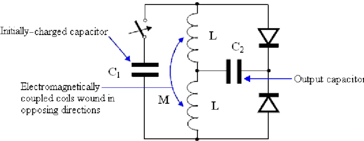
Consider the Electrodyne Corp. circuit (shown in "The Manual of Free-Energy Devices and Systems", 1986) tested by them for a period of three years:
Please note that when I shared this circuit diagram several years ago, someone persuaded me that the diodes were shown the wrong way round, and because of that, I have shown these diodes incorrectly. The diagram above is the one shown by the Electrodyne Corp. staff, and is correct.
As the switching used by this device was a mechanical device which has six switches where three are ON and three are OFF at any moment, the Electrodyne Corp. staff present the circuit diagram like this:
It is recommended that this simple-looking circuit has an inductive load, preferably a motor, but consider the results of that very extended period of testing. If the switching rate and switching quality were of a sufficiently high standard, then the load could be powered indefinitely. The batteries used were ordinary lead-acid batteries, and after the three years of tests, the batteries appeared to be in perfect condition. Their tests revealed a number of very interesting things. If the circuit was switched off and the batteries discharged to a low level, then when the circuit was switched on again, the batteries returned to full charge in under one minute. No heating occurred in the batteries in spite of the massive charging rate. If the circuit was switched off and heavy current drawn from the batteries, then heat would be produced which is quite normal for battery discharging. The system operated lights, heaters, television sets, small motors and a 30-horsepower electric motor. If left undisturbed, with the circuit running, then each battery would charge up to nearly 36 volts with no apparent ill effects. Control circuitry was developed to prevent this over-charging. This, of course, is easy to do as all that is required is to place a relay across one battery and have it disconnect the circuit when the battery voltage reaches whatever voltage is considered to be a satisfactory maximum voltage.
These test results show spectacular battery charging and battery performance, quite outside the normal range associated with these ordinary lead-acid batteries. Are they being fed very short, very sharp pulses, like the previous two systems? It would look as if they were not, but one other very interesting piece of information coming from Electrodyne is that the circuit did not operate correctly if the switching rate was less than 100 Hz (that is 100 switchings in one second). The Electrodyne switching was done mechanically via three discs mounted on the shaft of a small motor.
One other detail reported by the Electrodyne testers, is that if the switching speed exceeded 800 times per second, that it was “dangerous” but unfortunately, they didn’t say why or how it was dangerous. It clearly was not a major problem with the batteries as they were reported to be in good shape after three years of testing, so definitely no exploding batteries there. It could well be as simple a thing that the voltage on each battery rose so high that it exceeded the voltage specifications of the circuit components, or the loads being powered, which is a distinct possibility. It is possible that at more than 800 pulses per second, the charging produced excessive cooling which was not good for the batteries.
It is generally accepted that for a circuit of this nature to work properly, the switching has to be very sudden and very effective. Most people have an immediate urge to use solid-state switching rather than the mechanical switching used by Electrodyne. A 'thyristor' or 'SCR' might be suitable for this, but the sharp switching of a PCP116 isolator driving an IRF540 FET is impressive and a TC4420 FET-driver could substitute for the opto-isolator if preferred. It is possible that having a slight delay after the switches have turned On and Off, can prove very effective.
The Electrodyne Corp. staff used three identical discs mounted on the shaft of a motor as shown above. This allows the contact "brushes" to be located on opposite sides of the discs. There are, of course, many possible alternative constructions and I have been asked to show how I would choose to build this type of mechanical switching. The common idea of using mechanical relays is not very practical. Firstly, relays have trouble switching at the speeds suggested for this circuit. Secondly, with a contact life of say, two million and a switching speed of just 100 times per second, the relays would reach their projected lifespan after two weeks of operation, which is not a very practical option.
The objective is to have a simple construction which produces several switching for each revolution of the motor, easy adjustment of the timing of two separate sets of three switches (one set being OFF when the other set is ON), a construction which can be taken apart and then assembled again without altering the timing, and an electrical connection method which is straightforward. Obviously, the construction needs to use components which are readily available locally, and ideally, only require simple hand tools for the construction.
This suggested construction allows adjustment of the timing for both the start of the first set of switches and the start of the second set of switches. It should also be possible to introduce a short gap between the operation of these two sets of switches. This particular design is assuming a gap between each switching operation as that may be beneficial.
The switch contacts are rigid arms, pulled against the rotating drum by springs. The contacts touching the drum can be of various types and the ones shown are brass or copper cheese-head screws or bolts which are particularly convenient as they allow standard solder tags to be used to make the connections to the switch wires which then run across to ordinary electrical screw connectors, all of which can be accessed from above. I would suggest that four screw connectors should be used as a block as that allows them to be fastened in position with two screws which then stops them rotating when the wires are being tightened. There should not be any need for
The contact arms are shown as attached to each other in pairs. A lower level of construction accuracy can be allowed if they are all kept separate and a spring used for each arm rather than one spring for two arms as shown
in the drawing. I strongly recommend that the switching drum be solid and the brass or copper insets be a fair thickness and keyed securely into the drum. The surface of the inserts should be very gently eased into exact alignment with the surface of the drum, possibly by the very careful use of a small file or with a lathe if you are luck enough to have access to one.
The pivots for all of the switching arms can be a length of threaded rod with lock nuts at each end. There should be almost no movement of the switching arms when the drum is spinning, so no enormous precision is needed for the holes in the switching arms, through which the threaded rod runs. Having said that, it must be understood that each switch in the set of three, must turn On and OFF at the same time, so the contacts on the spring-loaded arms must slide on to and off the conducting strips in the switching cylinder, at exactly the same time.
The drawing shows three conducting inserts at each of eight evenly-spaced positions around the circumference of the drum. The number around the drum is not critical although this suggestion gives eight switchings per revolution. If you choose to use a different number, you need to remember that the positioning of the arms underneath the drum will be different. You need to arrange it so that just after one set runs off its conducting strips that the other set slides on to it's conducting strips. Both sets of switches must not be ON at the same time as that short-circuits the batteries, which is probably not a good idea.
The timing adjustment is achieved by moving the supporting block slightly, by easing the four clamping screws, sliding the block and tightening the screws again. This, of course, is done when the drum is not rotating.
Each set of six switching arms needs to have all of the arms exactly the same length between the sliding contact (shown as a bolt head) and the pivot hole. Each of the conducting strips inset into the drum, need to be aligned exactly and be exactly the same width, otherwise the switching action will be ragged and not properly synchronised.
The supports for the switching arms can be either a single block with slots cut in it or the easier construction shown, where it is fabricated from several standard rectangular pieces and glued and/or screwed together.
The unequal amount of conducting strip compared to the non-conducting part means that there will be a timing gap between each pair of On/Off switchings. In spite of that, the battery switching will be a 50% Duty cycle as required. The switching sequence will then be: On / Off / Pause, On / Off / Pause, On / Off / Pause ….. and that may well be a desirable arrangement as having an inter-pulse delay can be very good for battery charging.
However, please don’t imagine that the Tesla Switch described here is a ‘plug-and-play’ device which you can switch on and it will give you the sort of outputs mentioned above, as that is very much not the case. You need to see the Tesla Switch as being a long-term development project with high potential.
If you use the Tesla Switch circuit with manual switches and run each phase for many minutes before altering the switching, it can give up to four times better performance than running the load off the four batteries in parallel. That is not what the Tesla Switch is all about.
The Tesla Switch is one of the more difficult devices to get operational, in spite of the fact that it appeals to a large number of people. There are three possible modes of operation. If the diodes are turned the wrong way round so that they can feed current from each battery, then the operation will definitely be COP<1 but it will be a good deal better than operating without the switch circuit in place.
The second way has only been achieved by John Bedini as far as I am aware. This is where the circuitry is the same but the circuit components and connecting wires are adjusted very carefully to produce circuit resonance. When that happens, the circuit becomes self-powering although there is little or no extra power for other devices. The third way was developed and tested over three years by staff of the Electrodyne Corporation in America. In this version, the diodes are reversed and they only feed sharp voltage spikes back to the batteries, through the diodes which supposedly don’t allow current to flow in that direction. This is a very different form of operation where the operating power flows into the circuit from the local environment. The batteries need to be ‘conditioned’ through long periods of being operated this way as the ‘cold electricity’ used in the circuit is the opposite of the ‘hot electricity’ which the batteries have been using up to now. This long conditioning period is generally enough to make the average builder give up and believe that the circuit just doesn’t work. Dave Lawton was faced with exactly the same type of problem when he attempted to replicate Stan Meyer’s “Water Fuel Cell”. It appeared ‘dead’ and produced nothing during a whole month of testing, and then it suddenly burst into life, producing large amounts of HHO gas mix for almost no electrical input. Without his exceptional patience, Dave would never have succeeded. I believe that the same applies to the Tesla Switch when wired correctly with the diodes blocking current flow from the batteries – it is likely to take long-term and patient testing before the system swings into life.
Mechanical switching appears to work very well indeed, but if we decide to try using electronic circuitry, then we need to get an exact 50% Mark/Space ratio using a switching circuit, and so the following style of circuit might be used with a multi-turn preset resistor in position “A”:
Here, the frequency is not noticeably affected by adjustment through a very wide range of Mark/Space settings. The output from Pin 3 needs to drive a very sharp switching combination such as a TC4420 FET driver connected to IRF540 FETs.
Perhaps the circuit might be something like this:
This circuit allows the Mark-Space ratio to be adjusted without altering the frequency, and the frequency can be adjusted without affecting the Mark-Space setting in any way. In the Tesla Switch circuit, three switches need to be in their On position and the other three switches in their Off position, so we will arrange this by using the ordinary NE555 timer circuit shown above, with it's adjustable Mark-Space ratio (that is, variable On-to-Off ratio). We will use this circuit to drive six opto-isolators which will turn the six transistors On and Off in groups of three as required. To get the very high switching speed needed, PCP116 opto isolators should be used and although these are difficult to find, every effort should be made to get them as they enhance the switching speed.
Variable resistors come in a wide range of types. It is probably best to use a preset type as they are very easy to adjust and hold their settings very solidly. Also, when the correct setting is found, the component will be left on that position permanently. Some common types are:
where some can be adjusted from the top and others adjusted from the side. All of them can be mounted directly on the strip-board or printed circuit board used to construct the circuit.
However, the problem is to decide the direction of current flow and provide solid state components accordingly, as the Tesla Switch circuit almost certainly does not run with conventional electronic design. If you were to reverse the diodes shown in the first circuit diagram in this section, then the circuit will remain solidly COP<1 although some people have managed an operational improvement of 32 times over just using the batteries straight to power the load. With the diodes as shown in the first two diagrams in this section, the circuit operates by drawing in energy from the environment and that operates in an entirely different way in a circuit.
It is interesting to note that in the 1989 patent US 4,829,225 granted to Yury Podrazhansky and Phillip Popp, their evidence is that batteries charge much better and have a longer life if they are pulsed in a specific way. Their formula is that the battery should be given a powerful charging pulse lasting for a period of time between a quarter of a second and two seconds, the pulse being the Amp-Hour rating of the battery. That is, for an 85 AHr battery, the charging pulse would be 85 amps. That pulse is then followed by a discharging pulse of the same, or even greater current but only maintained for only 0.2% to 5% of the duration of the charging pulse. Those two pulses are then followed by a resting period before the pulsing is repeated. They quote the following examples of their experiences when using this method:
Battery: 9V alkaline 1.25V NiCad 0.5 AHr
15V NiCad 2 AHr
12V lead-acid 40 AHr
Charging current: 0.5 Amps 1.2 Amps 3.0 Amps 48 Amps
Charging period: 550 mS 700 mS 500 mS 850 mS
Discharge current: 6 Amps 6 Amps 14 Amps 85 Amps
Discharge period: 2 to 3 mS 2 mS 2 mS 3 mS
Rest period: 15 to 20 mS 7 to 10 mS 10 mS 15 mS
Charging range: 50% to 100% 20% to 100% 20% to 100% 20% to 100% Total charging time: 12 to 15 mins 20 mins 35 to 40 mins 40 mins
Interestingly, this appears to confirm the charging potential of the Tesla Switch style of operation, especially if there is a short rest period between the two sets of switch operations.
Bozidar Lisac’s Power-Boosting System.
Recently, a patent application has been lodged on what is effectively the Ron Cole one-battery switch and the Tesla Switch. I must admit to being highly doubtful about the notion of using capacitors as an energy source (unless the switching frequency is so high that the capacitors have insufficient time for their voltage to drop significantly), I am including the re-worded patent here. Some experimenters have reported overall battery energy gains with switching speeds of 0.5 Hz or less, which means that in circuits of that type, mechanical switching should give a reasonable switch contact life. This patent has needed a fair degree of attention as the person writing it does not have a full grasp of English and confused the word "load" with the word "charge". Let me say again, that the following patent application is included here primarily for interest sake, rather than being the definitive way of making a circuit of this type.
Patent Application US20080030165 7th February 2008 Inventor: Bozidar Lisac
METHOD AND DEVICE FOR SUPPLYING A LOAD WITH ELECTRIC ENERGY RECOVERY
ABSTRACT
In the invention an electric current circulates from the battery UB, through the electric motor M, and the diode D1 charges the capacitors CA and CB, connected in parallel, which, once charged, are connected in series, giving rise to a difference in voltage in relation to the battery, causing half the charge of the capacitors to be returned to the battery through the diode D2, whilst with a new parallel connection, the capacitors recharge, this charge being equal to that which had been previously transferred from the capacitors to the battery, so that by means of the cyclic connection of the capacitors in parallel and series the energy is transferred from the battery to the capacitors and from the capacitors to the battery, thus considerably extending the range of the battery and operation of the motor.
recovered using a self-rechargeable electricity source in which, which by means of a circuit, the current circulating from an accumulator or battery through a load, e.g. a motor, is fully returned to the same energy level, thereby considerably extending its range.
More specifically, two capacitors that are connected cyclically from parallel to serial and vice versa are charged through a motor during the connections in parallel, whilst in series connection, when its voltage doubles, they return the electricity, recharging the battery. This source represents a closed system which does not require an energy supply from the outside, except to compensate for the losses produced, the range of the battery being limited by the number of charges and discharges that the same technically permits.
BACKGROUND TO THE INVENTION
A load, such as an electric motor, is connected to a battery or accumulator with a certain charge, which will be progressively discharged by it, this discharge being directly proportional to the connection time and to the current circulating through the motor. It is therefore necessary to supply fresh energy from an external source to recharge it. Systems that enable the energy consumed by the load to be reused are not known in the state of the art.
DESCRIPTION OF THE INVENTION
A first aspect of the invention relates to a method for supplying a load with recovery of electrical energy, which comprises supplying a load with electrical energy deriving from the first electrical energy accumulator, and returning at least a proportion of that electrical energy after it passes through the load to the first accumulator for the purpose of recovering the energy supplied.
The electrical energy, after passing through the load, is recovered by second electrical energy accumulator, from where it is transferred to the first accumulator, giving rise to cyclic transfer of electrical energy between the first and second energy accumulators.
The recovery of energy from the second accumulator and transfer to the first accumulator may be achieved without passing the energy through the load. In another alternative implementation, the energy is recovered from the second accumulator and passed to the first accumulator through the load, in which case the polarity of the load is reversed during the recovery of energy through the load.
The transfer of energy is brought about by cyclically connecting two or more electrical energy accumulators between parallel and serial connections.
A second aspect of the invention relates to a device for supplying a load with recovery of electrical energy, which comprises a first electrical energy accumulator and a second electrical energy accumulator, where the load is connected between the first and second accumulators. The device may be provided in one embodiment with a unidirectional connection device, for example, a diode which is connected in parallel to the load, causing circulation of the electrical energy recovered after passing through the load, and via which the electrical energy is returned to the first accumulator.
The first electrical energy accumulator may be a battery. The second electrical energy accumulator might be two or more capacitors with switching to cyclically connect them between parallel and serial connection configurations. The invention constitutes a self-rechargeable source of electrical energy which enables the range of a battery to be considerably extended so that the current circulating from the same through a motor charges two capacitors connected in parallel, up to the voltage level of the battery, by means of contacts. These capacitors, once charged, are connected in series, producing double their voltage, and they then return the energy to the battery, thereby extending its range. Once the losses have been compensated for, the duration of the extended range depends on the charging and discharging properties of the capacitors.
The existence of the difference in voltage between the battery and the capacitors connected both in parallel and in series, and which give rise to the displacement of energy from the battery to the capacitors and vice versa, is used to supply the motor connected between the battery and the capacitors, comprising the self-rechargeable source of electrical energy.
When connected in parallel, the capacitors are charged through a motor and a diode, and when connected in series, they are charged through another diode, the voltage of the motor being half that of the battery. On the other hand, if the motor is connected between the battery and the serially-connected capacitors, the latter, which are charged in parallel through a diode and are discharged by means of the motor and the other diode, will supply
the motor with a voltage equal to that of the battery, whilst a capacitor connected in series to the winding of the motor guarantees its operation without loss of power.
Instead of the two capacitors, two batteries connected in series and another two connected in parallel may be used, between which batteries a motor is connected, the current circulating in this case from the batteries connected in series through the motor to the batteries connected in parallel. The serially-connected batteries are then connected in parallel, by means of switching contacts, and the other two parallel-connected batteries are then connected in series, reversing the direction of the current, whilst the connections of the motor are inverted by means of the simultaneous switching of other contacts in order to maintain the polarity and direction of rotation of the motor.
In one possible embodiment of the invention, another two capacitors and a transformer with two primary windings, or a motor with two windings are added to the device previously described, each pair of capacitors cyclically switching from parallel to serial connection and vice versa so that during the parallel connection cycles, two of the capacitors are charged through one of the windings up to the voltage level of the battery at the same time that the other two capacitors are connected in series, double their voltage and are discharged by means of a second winding to the battery.
The reduced level of energy losses brought about mainly by the dissipation of heat and in the capacitors, as well as by the charge factor of the batteries, is compensated for from an external source, and because the sum of the current circulating through a winding of the motor or transformer charging two of the capacitors and the current simultaneously circulating from the other two capacitors through the second winding, recharging the battery, plus the current which is supplied from the external source, is equal to zero, because of the work carried out by the motor or the loads which are connected to the alternating voltage induced in the secondary of the transformer, no discharge of the battery takes place.
DESCRIPTION OF THE DRAWINGS
In order to supplement the description now being given, and with the aim of contributing to a better understanding of the characteristics of the invention, according to a preferred practical embodiment, a set of drawings is attached as an integral part of this description, in which, for informative and non-restrictive purposes, the following is shown:
Fig.1 shows a practical circuit in which, by means of switching, two capacitors connected in parallel are charged from a battery through a motor and a diode, and after the contacts are switched, they are connected in series, thereby discharging the battery through another diode.
Fig.2 shows a practical circuit in which, through switching, the two capacitors are connected in parallel and are charged from a battery through a diode, and after the switching of the contacts they are connected in series, thereby charging the battery through the motor and the other diode.
Fig.3 shows the connection of the two batteries in series, connected through a motor to another two batteries connected in parallel, and which, by means of contacts, switch alternatively, this giving rise to effects similar to those described in relation to the use of the capacitors.
Fig.4 shows the electrical diagram corresponding to the connection between the battery and the two pairs of capacitors of a transformer with two primary and one secondary winding, in which an alternating voltage is induced which is rectified, filtered and converted to a sinusoidal voltage.
Fig.5 shows the electrical diagram of an alternating current motor with two windings connected between the battery and two pairs of capacitors.
Fig.6 shows the electrical diagram of a direct current motor with two windings connected between the battery and two pairs of capacitors, in which two switch contacts ensure their correct polarisation and direction of rotation.
PREFERRED EMBODIMENT OF THE INVENTION
In a preferred embodiment shown in Fig.1, the load consists of a direct current motor M, the battery UB, and the second accumulator which consists of a pair of capacitors CA and CB. The capacitors CA and CB are connected to each other in parallel by means of two switches S1 and S2. These capacitors are charged through the motor M and diode D1 to a voltage level equal to that of the battery UB, the charge being Q = (CA+CB)UB, and while these capacitors are being charged, the motor M is rotating.
When both capacitors are fully charged, they are connected in series by the switch contacts S1 and S2. This produces a voltage which is twice the value of the voltage of the battery UB, resulting in the charge which is given by Q = 2 x UB x (CA+CB) / 2 which is Q = (CA+CB)UB, which shows that once charged, the charge Q of both capacitors is identical both in parallel and in series.
Diodes D1 and D2 ensure that current flow through the motor M is only ever in one direction. Immediately after capacitors CA and CB are connected in series, they return half of their charge through diode D2. Switches S1
and S2 then connect the capacitors CA and CB in parallel. In this arrangement, they start off with half of the battery voltage. They charge immediately, regaining the battery voltage through the motor M and the diode D1. By means of repeated cyclic switching of the capacitors CA and CB from parallel to serial connection mode, the current circulating from the battery UB through the motor M to the capacitors, and from these to the battery, recharging it and extending its range, constitutes a self-rechargeable source of electrical energy.
In a second practical embodiment shown in Fig.2, the motor M is connected between the battery UB and the capacitors CA and CB by means of the diode D2. The capacitors are charged directly through the diode D1 and are discharged through the motor M and the diode D2, the values of the charges on the capacitors CA and CB previously described in the example shown in Fig.1 remain unchanged, the difference in this circuit is that the voltage applied to the motor M is the full battery voltage in this case.
The charging rate of the capacitors CA and CB is determined by the intensity of the current flowing through the motor M, to which is connected in parallel, the capacitor CM which guarantees that the operation of the motor is maintained at maximum power. It is possible to substitute a battery, preferably a rapid charge battery, for capacitor CM.
In another embodiment shown in Fig.3, the first and second accumulators consist of pairs of batteries B1, B2 and B3, B4. Therefore, in this embodiment, two pairs of batteries are used instead of the capacitors CA and CB. Batteries B1 and B2 are connected to the switches S1 and S2, and the pair of batteries B3 and B4 are connected to the switches S3 and S4. The switches S1 to S4, connect the pairs of batteries with which they are associated, into series or parallel configurations, depending on the position of the switches.
connected batteries recharges the two parallel-connected batteries. The switches S1 to S4, which connect the batteries B1 and B2 in series and the batteries B3 and B4 in parallel then switch, thus reversing the direction of the current flow, and at the same time, the switches S5 and S6 change positions in order to maintain the correct polarity for the motor and its direction of rotation.
The two capacitors and the batteries may be switched by means of any mechanical, electromechanical, electrical, electronic or other element that meets the conditions described with the purpose of obtaining a self-rechargeable electrical energy source. These switching operations may be controlled by any known method, for example, a programmable electronic circuit.
In the preferred embodiments previously described, the load consists of a direct current motor, but as an expert in the field may understand, the load may also consist of any type of resistive (?) and/or inductive load.
Another preferred embodiment is shown in Fig.4, where a transformer T with two primary windings L1 and L2 is connected between the battery UB and the two pairs of capacitors C1 and C2, plus C3 and C4, causing the two capacitors C1 and C2 to switch their connections from parallel to serial and back again by means of the contacts S1 and S2, and causing the capacitors C3 and C4 to switch by means of contacts S3 and S4, so that during the cycles of connection of the capacitors C1 and C2 in parallel, the latter are charged via the winding L1 up to the voltage level of the battery, whilst at the same time the capacitors C3 and C4 are connected in series and provide double their voltage, the battery being discharged by means of the winding L2, in which case the charging and discharging currents to circulate in the same direction. On the other hand, during the cycles of connection in parallel of the capacitors C3 and C4, which are charged through the winding L2 up to the battery voltage level, the capacitors C1 and C2 are connected in series to provide double their voltage and are discharged into the battery through the winding L1. The direction of the charging and discharging current therefore changes, thus inducing in the secondary winding L3 an alternating voltage whose frequency depends on the speed of switching of the contacts mentioned, and after being rectified by means of the bridge of diodes P and filtered by the capacitor CP, the resultant DC voltage is converted to a sinusoidal voltage by means of a circuit K.
The connection in parallel of one pair of capacitors and the connection in series of the other pair take place at the same time. Therefore the sum of the current circulating from the battery through one of the windings, charging two of the capacitors, and the current circulating from the other two capacitors through the other winding to the battery, is approximately zero.
From an external energy source FE the minimum energy losses caused essentially by dissipation of heat and in the capacitors, as well as by the charging factor of the battery, are compensated for, with the result that the sum
of the current circulating from this source external to the battery and the charging and discharging currents of the capacitors is equal to zero. Therefore the battery is not discharged and its range does not depend on the work developed by the motors or the loads connected to the secondary winding L3 of the transformer T, since the greater the power of the loads, the higher the intensity of the charging and discharging currents of the capacitors.
Fig.5 shows another embodiment in which an alternating current motor M is connected to two windings L1 and L2 so that during the connections in parallel of the capacitors C1 and C2, the latter are charged by means of the winding L1 at the same time that the capacitors C3 and C4, connected in series, are discharged by means of the winding L2 to the battery UB, the charging and discharging current circulating through the windings in the same direction. The capacitors C1 and C2 are then connected in series and the capacitors C3 and C4 are connected in parallel. The direction of the charging and discharging current of the capacitors is therefore reversed, thus producing at terminals of the motor an alternating voltage with a frequency that depends on the speed of switching of the contacts. The energy losses caused are compensated for from an external source FE, the sum of the current circulating from this source to the battery and the currents circulating through the two windings during charging and discharging of the capacitors being equal to zero. The battery is therefore not discharged as a result of the work developed by the motor.
Fig.6 shows the connection of a direct current motor M to two windings L1 and L2 between the battery UB and the two pairs of capacitors C1 and C2 plus C3 and C4, so that during the connections in parallel two of the capacitors are charged by means of the winding L1, and during the simultaneous connections in series, the other two capacitors are charged by means of the winding L2 to the battery. Coinciding with the switching of the contacts S1, S2, S3 and S4, which connect to each pair of capacitors from parallel to serial and vice versa, the contacts S5 and S6 switch, polarising the windings of the motor so that the charging and discharging currents of the capacitors circulate in the same direction, producing a direct voltage. The sum of the current supplied from the external source FE and the charging and discharging currents of the capacitors is equal to zero, and thus there is no battery discharge.
Bob Boyce’s Toroid.
Consider also, Bob Boyce’s very effective pulsed toroid system. As the waveform fed to the toroid has to have very sharp rising and falling voltages, the toroid needs to be able to handle very high frequency signals, far higher than the number of pulses per second fed to the toroid. If the rising edge is very sharp (and it needs to be so fast that it won’t show on a 150 MHz oscilloscope), then as far as the toroid is concerned, there may be a similar falling edge one nano second later and so it needs to be able to respond to that sort of frequency. Consequently, the material and the windings need to be selected very carefully.
The toroid is a 6.5 inch iron-dust unit from MicroMetals, part number “T650-52” and it can be purchased through their web site: http://www.micrometals.com/pcparts/torcore7.html and it can be purchased in small quantities via their "samples requests", which can be submitted at http://www.micrometals.com/samples_index.html
There are four windings made on this core. The wire chosen to wind the transformer is most important. Bob uses solid teflon-covered silver-plated copper wire. It is very important that this wire is solid core and not stranded as stranded wire does not work here (due to the generation of inter-strand, phase-differential induced eddy currents). At this time, a supplier of this wire is http://www.apexjr.com.
Before any winding is done, the toroid is given a layer of the yellow 1P802YE winding tape available in 3" rolls, both the 1" and 2" widths from: http://www.lodestonepacific.com/distrib/pdfs/tape/1p802.pdf. It is very important to avoid using fiberglass winding tape anywhere in the construction of this wound toroid. Bob comments on this as follows: “Big warning here !!!! DO NOT USE FIBERGLASS WINDING TAPE !!!! A big box of 3M winding tape was ordered by accident so I tried it to see if it would work. It not only suppressed the acousto-resonance response of the entire wound toroidal core, but for some strange reason it also caused the electrostatic pulse response of the secondary to reverse polarity as well as reducing the signal amplitude to a mere 10% of what it was !! It totally negated the benefit of the teflon insulation”.
Having covered the toroid with a layer of the 1P802YE winding tape, the secondary winding is made. Again, it is very important that the teflon-covered, silver-plated solid copper wire is used. This is not a system which provides COP>1 performance if any old components are thrown together carelessly during the building process.
The winding turns must be evenly spaced where they fan out from the center of the core. They are tightly packed side by side in the centre opening and they must be wound tightly and the gaps between adjacent turns along the outer edge must be exactly the same. This is not to make the winding look “pretty” but if this is not done, then it will cause magnetic field errors that will lower the overall efficiency when the toroid is being used.
The secondary winding is made using 16 gauge wire which covers the entire length of the toroid as shown here:
If the spaces between the wires are not quite even, then the turns can be pushed into exactly the right place. It is sometimes convenient to use two-inch lengths of plastic strimmer line placed between the turns in order to get the spaces between the turns exactly the same. These can be held in place with a strip of the yellow winding tape:
The picture above has been taken to show what a partially prepared secondary winding looks like when its windings are being moved into their exact positions. When a section of the windings has been spaced accurately, the triangular gaps between the evenly-spaced turns are filled in with beeswax, made pliable using a heat gun. A plastic bottle pushed into the central hole can be helpful when doing this filling. When the beeswax has hardened on both sides of the toroid, the process is then repeated for the next group of turns.
So, to recap: the toroid is wrapped in tape, the secondary winding completed, extending the entire way around the toroid, the windings carefully spaced out so that the gaps around the outer edge of the toroid are exactly equal, the winding gaps filled with beeswax, and then the toroid covered with a layer of the yellow tape. There will normally be anything from 127 to 147 turns in the secondary winding due to manufacturing tolerances in the insulation of the wire and so the overall wire length will be about 100 feet.
The primary windings are now wound on top of the tape layer covering the secondary winding. As with the secondary, the direction of the turns is very important.
Please note that every winding starts by passing over the toroid and then being brought up on the outer side ready for the next turn. Each of the following turns proceed in a counter-clockwise direction, and finishes by passing under the toroid. Every winding is created in this way and the quality of workmanship is very important indeed when making these windings. Each winding needs to be tight and positioned exactly with turns touching each other in the centre of the toroid and positioned on the outer edge with exactly equal spaces between each turn. Your construction work has to be better than that of a commercial supplier and needs to reach the quality demanded by the military.
The three primaries are wound on top of the tape which covers the secondary winding. These three primary windings are spaced out equally around the toroid, that is, at 120 degree centres and the leads of the secondary winding are taken out through the gap between two of the primary windings and not taken out through the middle of a primary winding. As with the secondary winding, the primary winding turns are spaced out exactly, held in place with beeswax, and then tightly taped over. The primaries can have more than a single layer, and they are
wound with the same direction of winds as the secondary, and with the same care for exact turns spacing as needed for the secondary winding. Tape the entire core well with tightly-stretched PVC electrical tape after winding, to ensure that the primary windings do not move and then add an outer layer of the winding tape.
This toroid pulls in additional energy from the immediate environment when driven by very high quality voltage pulsing applied to each of the three primary windings. The full details of this system have not yet been disclosed, but Bob has said in open forum that he has demonstrated his toroid being pulsed with the secondary not connected to anything and the output is triple the current at twice the input voltage, with is COP=6. When the ends of the secondary are joined together the output current doubled, giving COP=12, that is, twelve times as much power output as the input which Bob had to supply to get that output. This is, of course, not a case of energy being created (which is not possible) but instead, it is a case of eleven times the input power being drawn in from the surrounding environment.
I have never seen the circuitry for this, but it may be as shown here:
As the output voltage is doubled, the battery bank being charged can be double the voltage of the battery supplying the input power. The choke in the lead from the input battery positive is to direct the power generated to the charging batteries. Each primary winding is driven by it’s own separate oscillator which has adjustable frequency and adjustable Mark/Space ratio, or “Duty Cycle”. The Duty Cycle is set initially to about 25% which means that the input power is turned off for three quarters of the time. The highest frequency oscillator is adjusted to give the largest charging output current. Then, the middle frequency oscillator is adjusted to give the highest charging output. Finally, the lowest frequency oscillator is adjusted to give the highest charging output. When that has been done, the Duty Cycle of each oscillator is lowered as far as possible without lowering the charging rate. An oscilloscope is not needed for any of these adjustments.
It should be noted that what was marked as the “Start” of each primary winding in the diagrams showing how each winding is done, is connected to positive power supply line and the end marked “Finish” is connected to the output of the oscillator. This connection arrangement is very important because connecting them the other way round is likely to give a much lower performance.
The three oscillators are quite independent of each other and are free-running. In other words, they are not synchronised in any way and will produce all sorts of different combinations of composite output waveforms as a result of this arrangement. It must be noted that this is not a system which produces a rotating magnetic field as the windings are not pulsed sequentially. As already mentioned, the voltage output waveform from each of the oscillators must have very sharp rise and fall times and the output must, of course, be capable of supplying sufficient current to power the primary windings.
I have never seen an explanation of how this system works, and please remember that the circuit shown above is based on my guesswork and does not come from Bob Boyce. However, I will now suggest a possible mechanism for the way that the circuit works, and for it, let us assume that there is only the highest frequency oscillator connected: When there is an output pulse from the oscillator, a powerful current passes through the primary winding to which it is connected. This generates a strong magnetic pulse. But, since the winding is around a high-quality toroidal core, nearly all of the magnetic flux races around the toroid instead of radiating outwards.
(This suggests that if there were four primary windings that there would be an increased COP result for that arrangement. If that were done, then the fourth oscillator might run at around 85,600 Hz). The short-circuiting of the ends of the secondary winding produces a further increase in the output. I would suggest that this may be due to the fact that the turns ratio of the primary-to-secondary winding, produces a much higher voltage in the secondary winding. If the ends of the secondary winding are connected, then that induced voltage will generate a strong electrical current flowing through the secondary winding. That current will in turn, generate an even greater magnetic pulse, both in the toroid and in the primary windings which are wound around the secondary winding. This enhanced magnetic pulse may account for the enhanced electrical output to the battery bank being charged. Please remember that this not a matter of fact, but just a suggestion which I am putting forward as being a possible explanation of how the circuit is functioning.
Please remember that the toroid has to be able to handle frequencies far higher than the pulsing rate which is applied to it. A high-frequency waveform looks like this:
If you apply that frequency to Bob's toroid, then the toroid needs to be able to handle the waveform cleanly, without degrading it in any way. For this sort of application, an iron-dust toroid such as the MicroMetals product is essential. What many people have difficulty in seeing, is that even if the overall frequency of the signal is lower, as shown here:
in order for the rising edge of the waveform to be handled cleanly, the toroid has to be able to handle a very high frequency signal. The toroid doesn't "know" that the leading edge of the waveform is not going to be followed by a whole stream of very short, very fast, frequency pulses. So the toroid has to be able to handle high-frequency waveforms in order to deal with the very sharply rising leading edge which is essential for the successful operation of this and many other free-energy devices.
Don Smith’s High-Power Devices.
Don Smith is a very talented American who has understood all of Tesla's work and has produced literally dozens of practical devices based on his understanding. You will find more specific details in chapter 3, but in broad outline, a twelve-volt battery can be used to generate the pulsing magnetic field needed to nudge the local environment into providing massive amounts of electrical energy. The device described in detail in chapter 3, has an output of around 160 kilowatts, which is far, far more than any individual would need. In other words, it is a device which could easily power your home, and considering that an electric car needs about 65 kilowatts, one could easily power a vehicle, making it into a fuel-less mode of transport. This is not magic, just standard electrical theory being applied correctly for a change.
The key component in many of Don's devices is the humble, commercial power supply used to drive neon sign displays. This module produces some 9,000 volts at a frequency of 35,100 Hz (cycles per second). As Don points out, when you double the pulsing frequency and double the pulsing voltage, the available power goes up by a factor of sixteen times, because the effect of both of these things is squared. You will recall that Bob Boyce is pulsing his toroid very sharply at 42,000 Hz and that high frequency has a major effect on the power produced in his system.
Don then boosts his working voltage further with a step-up transformer called a Tesla Coil. This brings us into an area of massive power. People have the very mistaken idea that a Tesla Coil can only produce voltage and not current. The reality is that if the primary coil is positioned in the centre of the secondary coil, then the voltage and current produced will be roughly the same, and that is a very, very high level of power. One device of Don's looks like this:
This prototype is actually more complicated than it needs to be. It uses three very high-voltage capacitors which are not necessary if you opt for a slightly different method of construction. However, in this version, the twelve-volt battery (which is not shown), powers a true sine-wave inverter in order to provide the mains twelve-voltage and frequency needed by the neon-tube driver circuit. The voltage limitations of the capacitors, in particular, the 8,000-volt output storage capacitors, make the 9,000 volt output of the neon-tube driver too much for safe usage. To deal with this, Don uses a Variac-style variable transformer to lower the voltage supplied to the neon-tube driver circuit, and this lets him limit the output voltage to the 8,000 volts of the output storage capacitors.
A key detail is that the wire length in the turns of the short primary winding of the Tesla Coil is exactly one quarter of the wire length of the turns in the long secondary winding. This makes the coils resonate which is a vital factor in the operation. The final, exact tuning, can be done by sliding the primary coil to a slightly different position. In this prototype, Don chose to do the final fine tuning by attaching a small capacitor across each of the windings. This is not necessary.
In the prototype shown above, Don then uses four diodes to rectify the output to DC to feed the storage capacitors. This results in an 8,000 volt supply which can provide 20 amps of current. That is an output power of 160 kilowatts, and is limited by the output capacitor voltage rating.
Don points out that it is not necessary to do it that way and instead, a step-down transformer can be used to lower the output voltage and boost the available current. If this is done, then the voltage limitations disappear (provided that you are using very high-voltage cables) and so no Variac is needed and no high-voltage capacitors are needed either.
There are two options. Either you can aim for a mains-voltage, mains-frequency, AC output, or you can produce a DC output and use an off-the-shelf inverter to run any mains equipment powered by the device. With the first option, Don connects a single resistor across the primary of the step-down transformer and that drags the frequency down to the wanted level, provided that the resistor has the right value:
The alternative method which aims for a DC output does not need to alter the frequency:
In both of these cases, the twelve volt driving battery can be charged continuously by part of the output power, and there are various ways of doing that. However, care needs to be taken that the battery is not overcharged as the input power is very low.
You will notice the similarity between Bob Boyce's toroid system and Don Smith's Tesla Coil system. In each case, a very carefully wound circular winding is pulsed at high frequency, and in each case, substantial amounts of excess electrical power becomes available, flowing in from the surrounding environment, courtesy of the pulsating magnetic field.
Tariel Kapanadze’s Self-Powered Generators.
Tariel Kapanadze produced a similar style of device which is self-powered and produces a mains electricity output. He has demonstrated this for a TV documentary:
and any details available are in chapter 3.
Steven Mark’s Self-Powered “TPU” Generator.
Steven Mark’s Toroidal Power Unit. Fairly recently, Steven Mark placed a video of a self-powered, circular coil device on YouTube. This device was demonstrated powering both itself and a 100 watt light bulb. If the video is still in place, then you can see it at
It has been said that Steven has sold the rights to his design and the building details have not been disclosed publicly. A number of attempts to replicate Steven’s device are being made at the present time, one of the best known is at the http://www.overunity.com/index.php/topic,2535.0.html forum where interesting tests have been run on a variety of alternative constructions, mainly based on coils placed around a central Mobius loop. A Mobius loop is an arrangement where a wire loop has no starting point or ending point. The following diagram attempts to show how this is done, using a small inner loop inside a larger outer loop. In actual practice, the two loops are almost identical in size:
At the time of writing, although development work is continuing, nobody has replicated Steven’s TPU. The forum strategy is to place three coils around the Mobius loop and experiment with powering those coils with different forms of pulsed signals at different frequencies. The arrangement is like this:
This is getting very close to Bob Boyce’s toroidal transformer system which picks up substantial amounts of excess power from the environment. Instead of using a Mobius loop, Bob uses a powdered-iron toroidal core, wrapped with the secondary winding around the whole of it’s length:
Then, on top of the secondary winding, three equally-spaced primary windings are wound on top of the secondary, and driven by electronics which is positioned inside the toroid as that is the place least affected by the magnetic fields produced by the system:
Let me stress again, that a toroidal core like these ones is potentially very dangerous, especially when pulsed with a high-frequency rotating magnetic field. An arrangement like that taps into the zero-point energy field which has unlimited power and power surges are liable to occur. Bob Boyce states that it is perfectly possible to get power surges of 10,000 amps which will not only burn out the equipment, but can also trigger a lightning strike directly at the equipment, and you, standing beside it. Bob was hit by a strike of this nature and you should remember that Nikola Tesla burnt out a whole power station when the input from the zero-point energy field exceeded the station’s capacity by a major factor. These things are not toys, and the power which is being tapped, is literally unlimited.
Recently, Sterling Allan interviewed Jack Durban – see some of the details at Sterling’s web site:
http://peswiki.com/index.php/Article:Jack_Durban's_experience_with_Steve_Marks_Toroid_Generator and Jack made several statements about the Steven Mark device. You need to make up your own mind about how reliable the information coming from Jack actually is. Jack states that he has a “photographic memory” and yet he is unable to remember the number of an important patent which he had recently discussed with Sterling and unable to remember important details shown in his high-resolution video of Steven’s device operating. I know of no way of reconciling those statements, and that raises concerns for me personally. Jack also makes wholly unsupported and unnecessary allegations about the character and abilities of Steven which raises further doubts about the reasons for, and accuracy of the statements made. However, it seems necessary to note these statements, some of which are as follows:
According to Jack, the device was not invented by Steven and he suspects it was based on Tesla’s patent No. 381,970 “System of Electrical Distribution” :