Series MSD
No part of this manual may be reproduced in any form or by any means (including elec-tronic storage and retrieval or translation into a foreign language) without prior agree-ment and written consent from Agilent Technologies, Inc. as governed by United States and international copyright laws.
Manual Part Number
G3170-90036
Edition
Fourth edition, June 2012 Replaces G3170-90030 Printed in USA
Agilent Technologies, Inc. 5301 Stevens Creek Boulevard Santa Clara, CA 95052
The material contained in this docu-ment is provided “as is,” and is sub-ject to being changed, without notice, in future editions. Further, to the max-imum extent permitted by applicable law, Agilent disclaims all warranties, either express or implied, with regard to this manual and any information contained herein, including but not limited to the implied warranties of merchantability and fitness for a par-ticular purpose. Agilent shall not be liable for errors or for incidental or consequential damages in connec-tion with the furnishing, use, or per-formance of this document or of any information contained herein. Should Agilent and the user have a separate written agreement with warranty terms covering the material in this document that conflict with these terms, the warranty terms in the sep-arate agreement shall control.
C A U T I O N
A CAUTION notice denotes a hazard. It calls attention to an operating procedure, practice, or the like that, if not correctly performed or adhered to, could result in damage to the product or loss of important data. Do not proceed beyond a CAUTION notice until the indicated conditions are fully understood and met.
WA R N I N G
A WARNING notice denotes a hazard. It calls attention to an operating procedure, practice, or the like that, if not correctly performed or adhered to, could result in personal injury or death. Do not proceed beyond a
WARNING notice until the indicated conditions are fully understood and met.
maintaining the Agilent 5975 Series Gas Chromatograph/Mass Selective Detector (GC/MSD) system.
1 “Introduction”
Chapter 1 describes general information about the 5975 Series MSDs, including a hardware description, general safety warnings, and hydrogen safety information.
2 “Installing GC Columns”
Chapter 2 shows you how to prepare a capillary column for use with the MSD, install it in the GC oven, and connect it to the MSD using the GC/MSD interface.
3 “Operating in Electron Impact (EI) Mode”
Chapter 3 describes basic tasks such as setting temperatures, monitoring pressures, tuning, venting, and pumpdown. Much of the information in this chapter also applies to CI operation.
4 “Operating in Chemical Ionization (CI) Mode”
Chapter 4 describes additional tasks necessary to operate in CI mode.
5 “General Maintenance”
Chapter 5 describes maintenance procedures common to both EI and CI instruments.
6 “CI Maintenance”
Chapter 6 describes maintenance procedures unique to CI MSDs.
A “Chemical Ionization Theory”
The Instrument Utilities DVD that ships with your instrument provides an extensive collection of online help, videos, and books for the Agilent 7890A GC, 7820A GC, 6890N GC, 6850 GC, 5975T LTM GC/MS, 7693A ALS, and the 7683B ALS. Included are localized versions of the information you need most, such as:
• Getting Familiar documentation • Safety and Regulatory guides • Site Preparation checklists • Installation information • Operating guides
• Maintenance information • Troubleshooting details
5975 MSD Version 10 Abbreviations Used 11 The 5975 Series MSD 13
CI MSD Hardware Description 15 Important Safety Warnings 17 Hydrogen Safety 19
GC precautions 19
Safety and Regulatory Certifications 24 Cleaning/Recycling the Product 27 Liquid Spillage 27
Moving or Storing the MSD 27 2 Installing GC Columns
Columns 30
To reconfigure a 6850 GC column on its basket 32 To prepare a capillary column for installation 37 To install a capillary column in a split/splitless inlet 39 To condition a capillary column 41
To install a capillary column in the GC/MSD interface 43 Agilent 7890A and 7820A, and 6890 GCs 43
6850 GC 45 3 Operating in Electron Impact (EI) Mode
Operating the MSD from the Data System
LCP Status Messages 53
ChemStation Loading <timestamp> 53 Executing <type>tune 53
Instrument Available <timestamp> 53 Loading Method <method name> 53 Loading MSD Firmware 53
Loading OS 54
<method> Complete <timestamp> 54 Method Loaded <method name> 54 MS locked by <computer name> 54 Press Sideplate 54
Run: <method> Acquiring <datafile> 54 To view system status during startup 54 LCP Menus 55
The EI GC/MSD Interface 58 Before You Turn On the MSD 60 Pumping Down 61
Controlling Temperatures 61 Controlling Column Flow 62 Venting the MSD 63
To view MSD analyzer temperature and vacuum status 64 To set monitors for MSD temperature and vacuum status 66 To set the MSD analyzer temperatures 67
To set the GC/MSD interface temperature from the ChemStation 69
To tune the MSD 75
To verify system performance 76
High-Mass Testing (5975 Series MSDs) 77 To remove the MSD covers 80
To vent the MSD 82
To open the analyzer chamber 84 To close the analyzer chamber 87 To pump down the MSD 91 To move or store the MSD 93
To set the interface temperature from the GC 95 4 Operating in Chemical Ionization (CI) Mode
General Guidelines 98 The CI GC/MSD Interface 99 To Operate the CI MSD 101
To switch from the EI source to the CI source 102 To pump down the CI MSD 103
To set up the software for CI operation 104
To operate the reagent gas flow control module 106 To set up methane reagent gas flow 109
To use other reagent gases 111
To switch from the CI source to the EI source 115 CI Autotune 116
To verify PCI performance 122 To verify NCI performance 123 To monitor high vacuum pressure 124 5 General Maintenance
Before Starting 128
Maintaining the Vacuum System 133 6 CI Maintenance
General Information 140
To Set Up Your MSD for CI Operation 141 A Chemical Ionization Theory
Chemical Ionization Overview 146 Positive CI Theory 148
1
Introduction
5975 MSD Version 10 Abbreviations Used 11 The 5975 Series MSD 13 CI MSD Hardware Description 15 Important Safety Warnings 17Many internal parts of the MSD carry dangerous voltages 17 Electrostatic discharge is a threat to MSD electronics 17 Many parts are dangerously hot 18
The oil pan under the standard foreline pump can be a fire hazard 18 Hydrogen Safety 19
Dangers unique to GC/MSD operation 20 Hydrogen accumulation in an MSD 20 Precautions 22
Safety and Regulatory Certifications 24 Information 24
Symbols 25
Electromagnetic compatibility 26 Sound emission declaration 26 Cleaning/Recycling the Product 27 Liquid Spillage 27
Moving or Storing the MSD 27
This manual describes the operation, and routine maintenance of the Agilent Technologies 5975 Series MSD.
5975 MSD Version
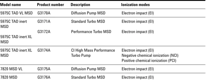
5975 Series MSDs are equipped with a diffusion pump or one of two turbomolecular (turbo) pumps. The serial number label displays a product number (Table1) that indicates what kind of MSD you have.
Table 1 Available high vacuum pumps
Model name Product number Description Ionization modes
5975C TAD VL MSD G3170A Diffusion Pump MSD Electron impact (EI) 5975C TAD inert MSD 5975C TAD inert XL MSD G3171A G3172A Standard Turbo MSD Performance Turbo MSD
Electron impact (EI) Electron impact (EI)
5975C TAD inert XL MSD
G3174A CI High Mass Performance Turbo Pump
Electron impact (EI)
Negative chemical ionization (NCI) Positive chemical ionization (PCI) 7820 MSD VL G3175A Diffusion Pump MSD Electron impact (EI)
Abbreviations Used
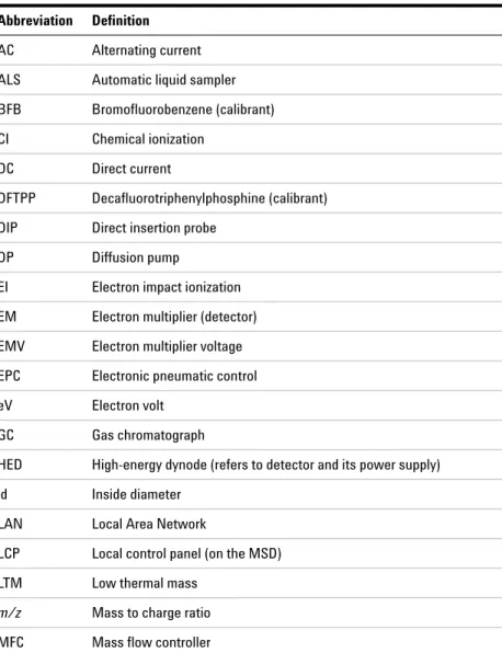
The abbreviations in Table2 are used in discussing this product. They are collected here for convenience.
Table 2 Abbreviations
Abbreviation Definition
AC Alternating current ALS Automatic liquid sampler BFB Bromofluorobenzene (calibrant) CI Chemical ionization
DC Direct current
DFTPP Decafluorotriphenylphosphine (calibrant) DIP Direct insertion probe
DP Diffusion pump
EI Electron impact ionization EM Electron multiplier (detector) EMV Electron multiplier voltage EPC Electronic pneumatic control eV Electron volt
GC Gas chromatograph
HED High-energy dynode (refers to detector and its power supply) id Inside diameter
LAN Local Area Network
LCP Local control panel (on the MSD) LTM Low thermal mass
m/z Mass to charge ratio MFC Mass flow controller
MSD Mass Selective Detector NCI Negative CI
OFN Octafluoronaphthalene (calibrant) PCI Positive CI
PFDTD Perfluoro-5,8-dimethyl-3,6,9-trioxydodecane (calibrant) PFHT 2,4,6-tris(perfluoroheptyl)-1,3,5-triazine (calibrant) PFTBA Perfluorotributylamine (calibrant)
Quad Quadrupole mass filter RF Radio frequency
RFPA Radio frequency power amplifier Torr Unit of pressure, 1 mm Hg Turbo Turbomolecular (pump)
Table 2 Abbreviations (continued)
The 5975 Series MSD
The 5975 Series MSD is a stand-alone capillary GC detector for use with an Agilent Series Gas Chromatograph (Table3). The MSD features:
• Local Control Panel (LCP) for locally monitoring and operating the MSD • One of three different high vacuum pumps
• Rotary vane foreline pump
• Independently MSD heated electron-ionization ion source • Independently MSD heated hyperbolic quadrupole mass filter • High-energy dynode (HED) electron multiplier detector • Independently GC heated GC/MSD interface
• Chemical ionization (EI/PCI/NCI) modes available
Physical description
The 5975 Series MSD is a rectangular box, approximately 42cm high, 26 cm wide, and 65cm deep. The weight is 25kg for the diffusion pump mainframe,
26kg for the standard turbo pump mainframe, and 29kg for the performance turbo pump mainframe. The attached foreline (roughing) pump weighs an additional 11kg (standard pump).
The basic components of the instrument are: the frame/cover assemblies, the local control panel, the vacuum system, the GC interface, the electronics, and the analyzer.
Local control panel
The local control panel allows local monitoring and operation of the MSD. You can tune the MSD, run a method or a sequence, and monitor instrument status.
Vacuum gauge
The 5975 Series MSD may be equipped with a Micro-Ion Vacuum Gauge. The MSD ChemStation can be used to read the pressure (high vacuum) in the vacuum manifold. Operation of the gauge controller is described in this manual.
The gauge is required for chemical ionization (CI) operation.
Table 3 5975 series MSD models and features
Model Feature G3170A G3175A G3171A G3176A G3172A G3174A
High vacuum pump Diffusion Standard turbo
Performance turbo
Performance turbo Optimal He column flow mL/min 1 1 1 to 2 1 to 2 Maximum recommended gas flow
mL/min*
* Total gas flow into the MSD: column flow plus reagent gas flow (if applicable). 1.5 2.0 4.0 4
Maximum gas flow, mL/min†
† Expect degradation of spectral performance and sensitivity.
2 2.4 6.5 6.5 Max column id 0.25 mm (30 m) 0.32 mm (30 m) 0.53 mm (30 m) 0.53 mm (30 m) CI capability No No No Yes DIP‡ capability (3rd party)
‡ Direct insertion probe.
CI MSD Hardware Description
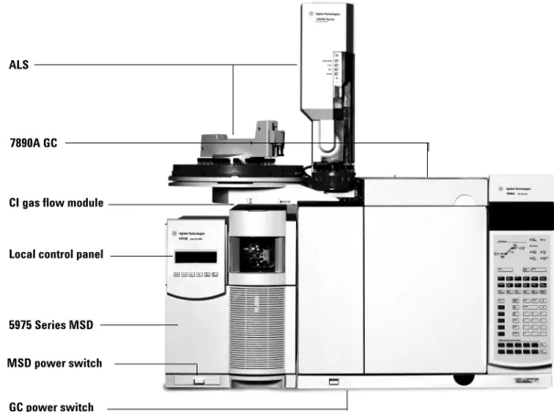
Figure1 is an overview of a typical 5975 GC/MSD system.
The CI hardware allows the 5975 Series MSD to produce high-quality, classical CI spectra, which include molecular adduct ions. A variety of reagent gases can be used.
Figure 1 5975 Series GC/MSD system
ALS
7890A GC
CI gas flow module
Local control panel
5975 Series MSD
MSD power switch
In this manual, the term “CI MSD” refers to the G3174A MSD and upgraded G3172A MSDs. It also applies, unless otherwise specified, to the flow modules for these instruments.
The 5975 Series CI system adds to the 5975 Series MSD: • EI/CI GC/MSD interface
• CI ion source and interface tip seal • Reagent gas flow control module
• Bipolar HED power supply for PCI and NCI operation
A methane/isobutane gas purifier is provided and is required. It removes oxygen, water, hydrocarbons, and sulfur compounds.
A high vacuum gauge controller (G3397A) is required for CI MSD and is recommended for EI also.
The MSD CI system has been optimized to achieve the relatively high source pressure required for CI while still maintaining high vacuum in the
quadrupole and detector. Special seals along the flow path of the reagent gas and very small openings in the ion source keep the source gases in the ionization volume long enough for the appropriate reactions to occur. The CI interface has special plumbing for reagent gas. A spring-loaded insulating seal fits onto the tip of the interface.
Switching back and forth between CI and EI sources takes less than an hour, although a 1- to 2-hour wait is required to purge the reagent gas lines and bake out water and other contaminants. Switching from PCI to NCI requires about 2
Important Safety Warnings
There are several important safety notices to always keep in mind when using the MSD.
Many internal parts of the MSD carry dangerous voltages
If the MSD is connected to a power source, even if the power switch is off, potentially dangerous voltages exist on:
• The wiring between the MSD power cord and the AC power supply, the AC power supply itself, and the wiring from the AC power supply to the power switch.
With the power switch on, potentially dangerous voltages also exist on: • All electronics boards in the instrument.
• The internal wires and cables connected to these boards. • The wires for any heater (oven, detector, inlet, or valve box).
Electrostatic discharge is a threat to MSD electronics
The printed circuit boards in the MSD can be damaged by electrostatic discharge. Do not touch any of the boards unless it is absolutely necessary. If you must handle them, wear a grounded wrist strap and take other antistatic precautions. Wear a grounded wrist strap any time you must remove the MSD right side cover.
WA R N I N G
All these parts are shielded by covers. With the covers in place, it should be difficult to accidentally make contact with dangerous voltages. Unless specificallyinstructed to, never remove a cover unless the detector, inlet, or oven are turned off.
WA R N I N G
If the power cord insulation is frayed or worn, the cord must be replaced. Contact your Agilent service representative.Many parts are dangerously hot
Many parts of the GC/MSD operate at temperatures high enough to cause serious burns. These parts include but are not limited to:
• The inlets
• The oven and its contents • The detector
• The column nuts attaching the column to an inlet or detector • The valve box
• The foreline pump
Always cool these areas of the system to room temperature before working on them. They will cool faster if you first set the temperature of the heated zone to room temperature. Turn the zone off after it has reached the setpoint. If you must perform maintenance on hot parts, use a wrench and wear gloves. Whenever possible, cool the part of the instrument that you will be maintaining before you begin working on it.
The oil pan under the standard foreline pump can be a fire hazard
Oily rags, paper towels, and similar absorbents in the oil pan could ignite and damage the pump and other parts of the MSD.
WA R N I N G
Be careful when working behind the instrument. During cool-down cycles, the GC emits hot exhaust which can cause burns.WA R N I N G
The insulation around the inlets, detectors, valve box, and the insulation cups is made of refractory ceramic fibers. To avoid inhaling fiber particles, we recommend the following safety procedures: ventilate your work area; wear long sleeves, gloves, safety glasses, and a disposable dust/mist respirator; dispose of insulation in a sealed plastic bag; wash your hands with mild soap and cold water after handling the insulation.WA R N I N G
Combustible materials (or flammable/non-flammable wicking material) placed under, over, or around the foreline (roughing) pump constitutes a fire hazard. KeepHydrogen Safety
Hydrogen is a commonly used GC carrier gas. Hydrogen is potentially explosive and has other dangerous characteristics.
• Hydrogen is combustible over a wide range of concentrations. At
atmospheric pressure, hydrogen is combustible at concentrations from 4% to 74.2% by volume.
• Hydrogen has the highest burning velocity of any gas. • Hydrogen has a very low ignition energy.
• Hydrogen that is allowed to expand rapidly from high pressure can self-ignite.
• Hydrogen burns with a nonluminous flame which can be invisible under bright light.
GC precautions
When using hydrogen as a carrier gas, remove the large round plastic cover for the MSD transfer line located on the GC left side panel. In the unlikely event of an explosion, this cover may dislodge.
WA R N I N G
The use of hydrogen as a GC carrier gas is potentially dangerous.WA R N I N G
When using hydrogen (H2) as the carrier gas or fuel gas, be aware that hydrogengas can flow into the GC oven and create an explosion hazard. Therefore, be sure that the supply is turned off until all connections are made and ensure that the inlet and detector column fittings are either connected to a column or capped at all times when hydrogen gas is supplied to the instrument.
Hydrogen is flammable. Leaks, when confined in an enclosed space, may create a fire or explosion hazard. In any application using hydrogen, leak test all
connections, lines, and valves before operating the instrument. Always turn off the hydrogen supply at its source before working on the instrument.
Dangers unique to GC/MSD operation
Hydrogen presents a number of dangers. Some are general, others are unique to GC or GC/MSD operation. Dangers include, but are not limited to:
• Combustion of leaking hydrogen.
• Combustion due to rapid expansion of hydrogen from a high-pressure cylinder.
• Accumulation of hydrogen in the GC oven and subsequent combustion (see your GC documentation and the label on the top edge of the GC oven door). • Accumulation of hydrogen in the MSD and subsequent combustion.
Hydrogen accumulation in an MSD
All users should be aware of the mechanisms by which hydrogen can accumulate (Table4) and know what precautions to take if they know or suspect that hydrogen has accumulated. Note that these mechanisms apply to all mass spectrometers, including the MSD.
WA R N I N G
The MSD cannot detect leaks in inlet and/or detector gas streams. For this reason, it is vital that column fittings should always be either connected to a column or have a cap or plug installed.Table 4 Hydrogen accumulation mechanisms
Mechanism Results
Mass spectrometer turned off A mass spectrometer can be shut down
deliberately. It can also be shut down accidentally by an internal or external failure. A mass
spectrometer shutdown does not shut off the flow of carrier gas. As a result, hydrogen may slowly accumulate in the mass spectrometer.
Mass spectrometer automated shutoff valves closed
Some mass spectrometers are equipped with automated diffusion pump shutoff valves. In these instruments, deliberate operator action or various failures can cause the shutoff valves to close. Shutoff valve closure does not shut off the flow of carrier gas. As a result, hydrogen may slowly accumulate in the mass spectrometer.
Mass spectrometer manual shutoff valves closed
Some mass spectrometers are equipped with manual diffusion pump shutoff valves. In these instruments, the operator can close the shutoff valves. Closing the shutoff valves does not shut off the flow of carrier gas. As a result, hydrogen may slowly accumulate in the mass spectrometer.
GC off A GC can be shut down deliberately. It can also be shut down accidentally by an internal or external failure. Different GCs react in different ways. If a 6890 GC equipped with Electronic Pressure Control (EPC) is shut off, the EPC stops the flow of carrier gas. If the carrier flow is not under EPC control, the flow increases to its maximum. This flow may be more than some mass spectrometers can pump away, resulting in the accumulation of hydrogen in the mass spectrometer. If the mass spectrometer is shut off at the same time, the accumulation can be fairly rapid.
Power failure If the power fails, both the GC and mass
spectrometer shut down. The carrier gas, however, is not necessarily shut down. As described previously, in some GCs a power failure may cause the carrier gas flow to be set to maximum. As a result, hydrogen may accumulate in the mass spectrometer.
Table 4 Hydrogen accumulation mechanisms (continued)
Precautions
Take the following precautions when operating a GC/MSD system with hydrogen carrier gas.
Equipment precaution
You MUST make sure the front side-plate thumbscrew is fastened finger-tight. Do not overtighten the thumbscrew; it can cause air leaks.
You must remove the plastic cover over the glass window on the front of a 5975 MSD. In the unlikely event of an explosion, this cover may dislodge.
General laboratory precautions
• Avoid leaks in the carrier gas lines. Use leak-checking equipment to periodically check for hydrogen leaks.
• Eliminate from your laboratory as many ignition sources as possible (open flames, devices that can spark, sources of static electricity, etc.).
• Do not allow hydrogen from a high pressure cylinder to vent directly to atmosphere (danger of self-ignition).
WA R N I N G
Once hydrogen has accumulated in a mass spectrometer, extreme caution must be used when removing it. Incorrect startup of a mass spectrometer filled with hydrogen can cause an explosion.WA R N I N G
After a power failure, the mass spectrometer may start up and begin the pumpdown process by itself. This does not guarantee that all hydrogen has been removed from the system or that the explosion hazard has been removed.WA R N I N G
Failure to secure your MSD as described above greatly increases the chance of personal injury in the event of an explosion.Operating precautions
• Turn off the hydrogen at its source every time you shut down the GC or MSD.
• Turn off the hydrogen at its source every time you vent the MSD (do not heat the capillary column without carrier gas flow).
• Turn off the hydrogen at its source every time shutoff valves in an MSD are closed (do not heat the capillary column without carrier gas flow).
• Turn off the hydrogen at its source if a power failure occurs.
• If a power failure occurs while the GC/MSD system is unattended, even if the system has restarted by itself:
1 Immediately turn off the hydrogen at its source.
2 Turn off the GC.
3 Turn off the MSD and allow it to cool for 1 hour.
4 Eliminate all potential sources of ignition in the room.
5 Open the vacuum manifold of the MSD to atmosphere.
6 Wait at least 10 minutes to allow any hydrogen to dissipate.
7 Start up the GC and MSD as normal.
When using hydrogen gascheck the system for leaks to prevent possible fire and explosion hazards based on local Environmental Health and Safety (EHS) requirements. Always check for leaks after changing a tank or servicing the gas lines. Always make sure the vent line is vented into a fume hood.
Safety and Regulatory Certifications
The 5975 Series MSD conforms to the following safety standards:
• Canadian Standards Association (CSA): CAN/CSA-C222 No. 61010-1-04 • CSA/Nationally Recognized Test Laboratory (NRTL): UL 61010–1 • International Electrotechnical Commission (IEC): 61010–1 • EuroNorm (EN): 61010–1
The 5975 MSD conforms to the following regulations on Electromagnetic Compatibility (EMC) and Radio Frequency Interference (RFI):
• CISPR 11/EN 55011: Group 1, Class A • IEC/EN 61326
• AUS/NZ
This ISM device complies with Canadian ICES-001. Cet appareil ISM est conforme a la norme NMB—001 du Canada.
The 5975 Series MSD is designed and manufactured under a quality system registered to ISO 9001.
Information
The Agilent Technologies 5975 Series MSD meets the following IEC
(International Electro-technical Commission) classifications: Equipment Class I, Laboratory Equipment, Installation Category II, Pollution Degree 2.
This unit has been designed and tested in accordance with recognized safety standards and is designed for use indoors. If the instrument is used in a manner not specified by the manufacturer, the protection provided by the instrument may be impaired. Whenever the safety protection of the MSD has been compromised, disconnect the unit from all power sources and secure the unit against unintended operation.
Refer servicing to qualified service personnel. Substituting parts or
Symbols
Warnings in the manual or on the instrument must be observed during all phases of operation, service, and repair of this instrument. Failure to comply with these precautions violates safety standards of design and the intended use of the instrument. Agilent Technologies assumes no liability for the customer’s failure to comply with these requirements.
See accompanying instructions for more information.
Indicates a hot surface.
Indicates hazardous voltages.
Indicates earth (ground) terminal.
Indicates potential explosion hazard.
Indicates radioactivity hazard.
Indicates electrostatic discharge hazard.
Indicates that you must not discard this
electrical/electronic product in domestic household waste.
Electromagnetic compatibility
This device complies with the requirements of CISPR11. Operation is subject to the following two conditions:
• This device may not cause harmful interference.
• This device must accept any interference received, including interference that may cause undesired operation.
If this equipment does cause harmful interference to radio or television reception, which can be determined by turning the equipment off and on, the user is encouraged to try one or more of the following measures:
1 Relocate the radio or antenna.
2 Move the device away from the radio or television.
3 Plug the device into a different electrical outlet, so that the device and the radio or television are on separate electrical circuits.
4 Make sure that all peripheral devices are also certified.
5 Make sure that appropriate cables are used to connect the device to peripheral equipment.
6 Consult your equipment dealer, Agilent Technologies, or an experienced technician for assistance.
7 Changes or modifications not expressly approved by Agilent Technologies could void the user’s authority to operate the equipment.
Sound emission declaration
Sound pressure
Sound pressure Lp <70 dB according to EN 27779:1991.
Schalldruckpegel
Cleaning/Recycling the Product
To clean the unit, disconnect the power and wipe down with a damp, lint-free cloth. For recycling, contact your local Agilent sales office.
Liquid Spillage
Do not spill liquids on the MSD.
Moving or Storing the MSD
The best way to keep your MSD functioning properly is to keep it pumped down and hot, with carrier gas flow. If you plan to move or store your MSD, a few additional precautions are required. The MSD must remain upright at all times; this requires special caution when moving. The MSD should not be left vented to atmosphere for long periods.
2
Installing GC Columns
Columns 30Conditioning columns 30 Conditioning ferrules 31 Tips and hints 31
To reconfigure a 6850 GC column on its basket 32 To prepare a capillary column for installation 37 To install a capillary column in a split/splitless inlet 39 To condition a capillary column 41
To install a capillary column in the GC/MSD interface 43
Before you can operate your GC/MSD system, you must select, install, and condition a GC column. This chapter will show you how to install and condition a column. For correct column and flow selection, you must know what type of vacuum system your MSD has. The serial number tag on the lower front of the left side panel shows the model number.
Columns
Many types of GC columns can be used with the MSD but there are some restrictions.
During tuning or data acquisition the rate of column flow into the MSD should not exceed the maximum recommended flow. Therefore, there are limits to column length and flow. Exceeding recommended flow will result in degradation of mass spectral and sensitivity performance.
Remember that column flows vary greatly with oven temperature. See “To measure column flow linear velocity” for instructions on how to measure actual flow in your column. Use the Flow Calculation software and Table5 to determine whether a given column will give acceptable flow with realistic head pressure.
Conditioning columns
Conditioning a column before it is connected to the GC/MSD interface is essential.
Table 5 Gas flows
Feature G3170A
G3175A
G3171A G3176A
G3172A G3174A
High vacuum pump Diffusion Standard turbo
Performance turbo
Performance turbo Optimal gas flow, mL/min*
* Total gas flow into the MSD = column flow + reagent gas flow (if applicable) 1 1 1 to 2 1 to 2 Maximum recommended gas flow,
mL/min
1.5 2 4 4
Maximum gas flow, mL/min†
† Expect degradation of spectral performance and sensitivity.
2 2.4 6.5 6.5 Maximum column id 0.25 mm (30 m) 0.32 mm (30 m) 0.53 mm (30 m) 0.53 mm (30 m)
A small portion of the capillary column stationary phase is often carried away by the carrier gas. This is called column bleed. Column bleed deposits traces of the stationary phase in the MSD ion source. This decreases MSD sensitivity and makes cleaning the ion source necessary.
Column bleed is most common in new or poorly crosslinked columns. It is much worse if there are traces of oxygen in the carrier gas when the column is heated. To minimize column bleed, all capillary columns should be
conditioned before they are installed in the GC/MSD interface.
Conditioning ferrules
Heating ferrules to their maximum expected operating temperature a few times before they are installed can reduce chemical bleed from the ferrules.
Tips and hints
• The column installation procedures for the 5975 Series MSDs is different from that for previous MSDs. Using the procedure from another instrument may not work and may damage the column or the MSD.
• You can remove old ferrules from column nuts with an ordinary push pin. • Always use carrier gas that is at least 99.9995% pure.
• Because of thermal expansion, new ferrules may loosen after heating and cooling a few times. Check for tightness after two or three heating cycles. • Always wear clean gloves when handling columns, especially the end that
will be inserted into the GC/MSD interface.
WA R N I N G
If you are using hydrogen as a carrier gas, do not start carrier gas flow until the column is installed in the MSD and the MSD has been pumped down. If the vacuum pumps are off, hydrogen will accumulate in the MSD and an explosion may occur. See “Hydrogen Safety” .WA R N I N G
Always wear safety glasses when handling capillary columns. Use care to avoid puncturing your skin with the end of the column.To reconfigure a 6850 GC column on its basket
Before installing a 6850, first reconfigure it to better position the column ends for installation in the GC MSD interface.
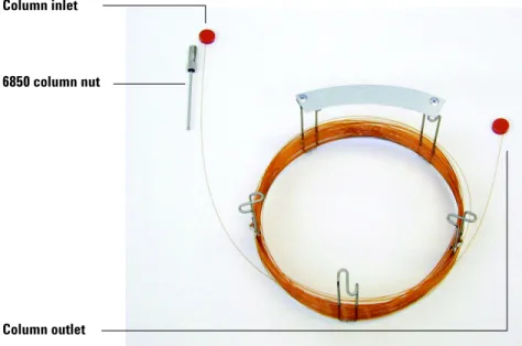
1 Lay the column (19091S-433E found in the GC ship kit) on a clean surface with the column label facing the user in the 12 o’clock position. Note that the inlet and outlet ends of the column are oriented the same as when a GC detector is used and the column outlet is positioned at the back (closer to the fan) of the column cage holder. See Figure2.
Figure 2 Column
Column inlet
Column outlet 6850 column nut
2 Remove the septum cap from the column OUTLET side and uncoil 2 column loops. See Figure3.
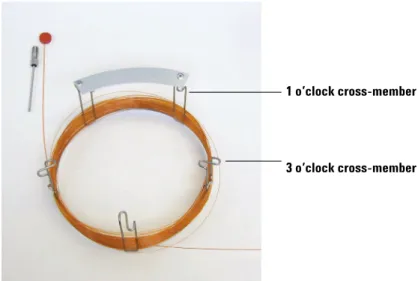
3 Attach three column clips (part number G2630-20890) to the column cage as follows:
• Attach one clip onto the back of the 1 o’clock cross-member piece of the column cage.
• Attach two clips onto the front of the 3 o’clock cross-member piece of the column cage.
These clips will help provide appropriate orientation of column ends for their insertion into the GC inlet and MSD interface.
Figure 3 Column with 2 uncoiled loops
1 o’clock cross-member
See Figure4.
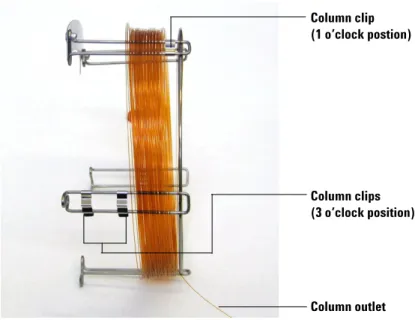
4 Feed the outlet side of the column through the 1 o’clock positioned clip so that the column outlet is pointing toward the front of the column cage. See
Figure5.
Figure 4 Column with column clips attached
Column clip (1 o’clock postion)
Column clips (3 o’clock position)
Column outlet
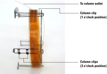
5 Next, feed the outlet side of the column through the 3 o’clock positioned clips so that the column outlet is pointing toward the back of the column cage. Make sure that the part of the column that is between the two clips does NOT extend above the column label. See Figure6.
Figure 5 Column fed through 1 o’clock position
To column outlet
Column clip (1 o’clock position)
Column clips (3 o’clock position)
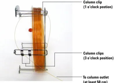
There should be approximately 50 cm of column extending beyond the 3
o’clock positioned clip.
6 Carefully rewind the remainder of the column outlet end around the column cage.
Figure 6 Column fed through 3 o’clock position
Column clip (1 o’clock postion) Column clips (3 o’clock position) To column outlet (at least 50 cm)
To prepare a capillary column for installation
Materials needed
• Capillary column
• Column cutter, ceramic (5181-8836) or diamond (5183-4620) • Ferrules
• 0.27-mm id, for 0.10-mm id columns (5062-3518) • 0.37-mm id, for 0.20-mm id columns (5062-3516) • 0.40-mm id, for 0.25-mm id columns (5181-3323) • 0.5-mm id, for 0.32-mm id columns (5062-3514) • 0.8-mm id, for 0.53-mm id columns (5062-3512) • Gloves, clean
• Large (8650-0030) • Small (8650-0029)
• Inlet column nut (5181-8830 for Agilent 7890A, 7820A and 6890, or 5183-4732 for 6850)
• Magnifying loupe
• Septum (may be old, used inlet septum)
Procedure
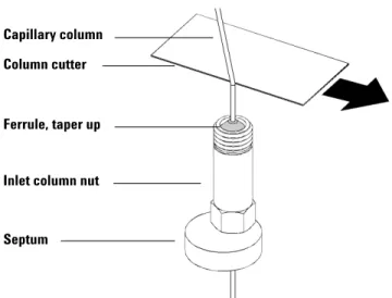
1 Slide a septum, column nut, and conditioned ferrule onto the free end of the column (Figure7). The tapered end of the ferrule should point away from the column nut.
2 Use the column cutter to score the column 2cm from the end.
3 Break off the end of the column. Hold the column against the column cutter with your thumb. Break the column against the edge of the column cutter.
4 Inspect the end for jagged edges or burrs. If the break is not clean and even, repeat steps2 and 3.
5 Wipe the outside of the free end of the column with a lint-free cloth moistened with methanol.
Figure 7 Preparing a capillary column for installation
Capillary column Column cutter
Ferrule, taper up
Inlet column nut
To install a capillary column in a split/splitless inlet
Materials needed • Gloves, clean • Large (8650-0030) • Small (8650-0029) • Metric ruler• Wrench, open-end, 1/4-inch and 5/16-inch (8710-0510)
To install columns in other types of inlets, refer to your Gas Chromatograph User Information.
Procedure
1 Prepare the column for installation ( “To prepare a capillary column for installation” on page 37).
2 Position the column so it extends 4 to 6mm past the end of the ferrule (Figure8).
Figure 8 Installing a capillary column for a split/splitless inlet
Insulation cup Reducing nut Capillary columnFerrule (inside nut)
Inlet column nut
Septum
3 Slide the septum to place the nut and ferrule in the correct position.
4 Insert the column in the inlet.
5 Slide the nut up the column to the inlet base and finger-tighten the nut.
6 Adjust the column position so the septum is even with the bottom of the column nut.
7 Tighten the column nut an additional 1/4 to 1/2turn. The column should not slide with a gentle tug.
8 Start carrier gas flow.
9 Verify flow by submerging the free end of the column in isopropanol. Look for bubbles.
To condition a capillary column
Materials needed
• Carrier gas, (99.9995% pure or better)
• Wrench, open-end, 1/4-inch and 5/16-inch (8710-0510)
Procedure
1 Install the column in the GC inlet ( “To install a capillary column in a split/splitless inlet” on page 39).
2 Allow the carrier gas to flow through the column for 5 minutes without heating the GC oven.
3 Ramp the oven temperature at 5°C/minute to 10°C above your highest analytical temperature.
4 Once the oven temperature exceeds 80°C, inject 5 µL methanol into the GC. Repeat two more times at 5-minute intervals. This helps remove any contamination from the column before it is installed into the GC/MSD interface.
5 Hold this temperature. Allow the carrier gas to flow for several hours.
6 Return the GC oven temperature to a low standby temperature.
WA R N I N G
Do not condition your capillary column with hydrogen. Hydrogen accumulation in the GC oven can result in an explosion. If you plan to use hydrogen as your carrier gas, first condition the column with ultrapure (99.999% or better) inert gas such as helium, nitrogen, or argon.
C A U T I O N
Never exceed the maximum column temperature, either in the GC/MSD interface, theSee also
For more information about installing a capillary column, refer to the application note Optimizing Splitless Injections on Your GC for High Performance MS Analysis, publication number 5988-9944EN.
To install a capillary column in the GC/MSD interface
Agilent 7890A and 7820A, and 6890 GCs
Materials needed
• Column cutter, ceramic (5181-8836) or diamond (5183-4620) • Ferrules
• 0.3-mm id, for 0.10-mm id columns (5062-3507)
• 0.4-mm id, for 0.20- and 0.25-mm id columns (5062-3508) • 0.5-mm id, for 0.32-mm id columns (5062-3506)
• 0.8-mm id, for 0.53-mm id columns (5062-3512) • Flashlight
• Hand lens (magnifying loupe) • Gloves, clean
• Large (8650-0030) • Small (8650-0029)
• Interface column nut (05988-20066) • Safety glasses
• Wrench, open-end, 1/4-inch and 5/16-inch (8710-0510)
Procedure
1 Condition the column (page 41).
2 Vent the MSD (page 82) and open the analyzer chamber (page 84). Be sure you can see the end of the GC/MSD interface.
3 If the CI interface is installed, remove the spring-loaded tip seal from the MSD end of the interface.
4 Slide an interface nut and conditioned ferrule onto the free end of the GC column. The tapered end of the ferrule must point towards the nut.
C A U T I O N
Note that the column installation procedure for the 5975 Series MSDs is different fromthat for most previous MSDs. Using the procedure from another instrument may result in poor sensitivity and possible damage to the MSD.
5 Slide the column into the GC/MSD interface (Figure9) until you can pull it out through the analyzer chamber.
6 Break 1cm off the end of the column (page 32). Do not let any column fragments fall into the analyzer chamber. They could damage the high vacuum pump.
7 Clean the outside of the free end of the column with a lint-free cloth moistened with methanol.
8 Adjust the column so it projects 1 to 2mm past the end of the interface.
Use the flashlight and hand lens if necessary to see the end of the column inside the analyzer chamber. Do not use your finger to feel for the column end.
Figure 9 Installing a capillary column in the GC/MSD interface
1 to 2 mm GC/MSD interface (MSD end) Analyzer chamber GC/MSD interface (GC end)
Interface column nut Column
9 Hand-tighten the nut. Make sure the position of the column does not change as you tighten the nut. Reinstall the spring-loaded tip seal if it was removed earlier.
10Check the GC oven to be sure that the column does not touch the oven walls.
11Tighten the nut 1/4 to 1/2 turn. Check the tightness after one or two heat cycles.
6850 GC
1 Carefully unwind the outlet end of the GC column until the 3 o’clock clip is reached.
2 Slide an interface column nut (part number 05988-20066) and ferrule (part number 5062-3508) onto the outlet end of the GC column.
The tapered end of the ferrule must point towards the nut.
3 Slide the column into the GC/MSD interface until the column protrudes into the analyzer chamber at least 5 cm.
4 Adjust the length of the column from the 3 o’clock clip to the back of the interface column nut to be 22–28 cm. SeeFigure 10.
5 Hand tighten the interface nut.
6 Carefully close the oven door while observing to see that the column does not develop sharp bends or touch the oven walls/floor. Try this procedure several times.
7 Loosen the interface nut and push the column an additional 3–5 cm into the analyzer chamber.
8 Make a clean cut of the column so that now only 3–5cm protrudes into the analyzer chamber.
9 Clean the outside of the free end of the column with a lint-free cloth moistened with methanol.
10Adjust the column so that it protrudes 1 to 2 mm into the analyzer chamber past the end of the GC/MSD interface, and hand tighten the nut. See
Figure 11.
Make sure the position of the column does not change as you retighten the nut.
Figure 10 Oven door opened and closed
11Repeat step6 to assure column integrity.
12Tighten the interface nut an additional 1/4 to 1/2 turn with a 1/4-inch open-end wrench.
Check the tightness after one or two heat cycles.
13Turn the GC on.
14Verify that the inlet temperature is set to 25 °C.
15Close the analyzer side plate, then reconnect the source power and side board control cables.
16Turn on the MSD power switch to initiate MSD pump down.
Press on the side plate of the MSD to achieve a good seal. Verify that the foreline pump and front fan turn on and that the foreline pump stops gurgling within 60 seconds.
Figure 11 MSD - GC column connection
1 to 2 mm GC/MSD interface (MSD end) Analyzer chamber GC/MSD interface (GC end)
Interface column nut Column
3
Operating in Electron Impact (EI) Mode
Operating the MSD from the Data System 51Operating the MSD from the LCP 51 LCP Status Messages 53
LCP Menus 55
The EI GC/MSD Interface 58 Before You Turn On the MSD 60 Pumping Down 61
Controlling Temperatures 61 Controlling Column Flow 62 Venting the MSD 63
To view MSD analyzer temperature and vacuum status 64 To set monitors for MSD temperature and vacuum status 66 To set the MSD analyzer temperatures 67
To set the GC/MSD interface temperature from the ChemStation 69 To monitor high vacuum pressure 71
To measure column flow linear velocity 73 To confirm column flow 74
To tune the MSD 75
To verify system performance 76
High-Mass Testing (5975 Series MSDs) 77 To remove the MSD covers 80
To vent the MSD 82
To open the analyzer chamber 84 To close the analyzer chamber 87 To pump down the MSD 91 To move or store the MSD 93
How to perform some basic operating procedures for the MSD.
C A U T I O N
The software and firmware are revised periodically. If the steps in these procedures donot match your MSD ChemStation software, refer to the manuals and online help supplied with the software for more information.
Operating the MSD from the Data System
The software performs tasks such as pumping down, monitoring pressures, setting temperatures, tuning, and preparing to vent. These tasks are described in this chapter. Data acquisition and data analysis are described in the manuals and online help supplied with the MSD ChemStation software.
Operating the MSD from the LCP
The local control panel (LCP) shows the status of the MSD or initiates a task on the MSD without using the Agilent GC/MSD ChemStation.
The GC/MSD ChemStation may be located anywhere on the site local area network (LAN), so the GC/MSD ChemStation might not be near the instrument itself. And because the LCP communicates with the GC/MSD ChemStation via the LAN, you can access GC/MSD ChemStation software functions, such as tuning and starting a run, right from the MSD.
Modes of operation
The LCP has two modes of operation: Status and Menu.
Status mode requires no interaction and simply displays the current status of the MSD instrument or its various communication connections. If you select [Menu], then [No/Cancel], you will be returned to the Status mode.
Menu mode allows you to query various aspects of the GC/MSD and to initiate some actions like running a method or sequence or preparing to vent the system.
To access a particular menu option:
N O T E
Only certain functions are available from the LCP; the GC/MSD ChemStation is thefull-featured controller for most instrument control operations.
Press [Menu] until the desired menu appears.
Use one or more of the following keys as appropriate to respond to prompts or select options:
After you make your selection, or if you cycle through all available menus, the display automatically returns to Status mode.
Pressing [Menu], then [No/Cancel], will always display the Status mode.
Pressing [No/Cancel] twice will always return to the Status mode.
Use [Up] to increase the displayed value or to scroll up (such as in a message list).
Use [Down] to decrease the displayed value or to scroll down (such as in a message list).
Use [Yes/Select] to accept the current value.
LCP Status Messages
The following messages may be displayed on the LCP to inform you of the status of the MSD system. If the LCP is currently in Menu mode, cycle through the menus to return to Status mode.
ChemStation Loading <timestamp>
The Agilent MSD Productivity ChemStation software is starting up.
Executing <type>tune
A tuning procedure is in progress (type = QuickTune or Autotune).
Instrument Available <timestamp>
The Agilent MSD Productivity ChemStation software is not running.
Loading Method <method name>
Method parameters are being sent to the MSD.
Loading MSD Firmware
The MSD’s firmware is being initialized.
The following messages alternately appear on the LCP if the MSD does NOT complete its bootup sequence properly:
Server not Found Check LAN Connection
Seeking Server Bootp Query xxx
These messages indicate that the MSD has not received its unique IP address from the Agilent Bootp Service. If the messages persist after you have logged onto your account on the GC/MSD ChemStation, consult the Troubleshooting section of the Software Installation manual.
Loading OS
The operating system of the instrument controller is being initialized.
<method> Complete <timestamp>
The run and subsequent data processing are done. The same message appears even if the run was terminated prematurely.
Method Loaded <method name>
Method parameters were sent to the MSD.
MS locked by <computer name>
MS parameters can only be changed from the GC/MSD ChemStation.
Press Sideplate
A reminder during startup to press the MSD sideplate to ensure an adequate vacuum seal.
Run: <method> Acquiring <datafile>
A run is in progress; data is being acquired to the designated data file.
To view system status during startup
1 The following messages are displayed on the LCP display during startup: • Press sideplate
• Loading OS
• Press sideplate
• Loading MSD Firmware
2 Continue to press the sideplate of the MSD until the MSD Ready message appears. This helps the instrument to pump down more quickly.
LCP Menus
To access a particular menu option, press [Menu] until the desired menu appears, then press [Item] until the desired menu item appears. Table6
through Table 11 list the menus and selections.
N O T E
Many menu items, especially on the ChemStation, MSmenus, have no effect when the instrument is acquiring data.Parameters, and MaintenanceTable 6 ChemStation menu
Action Description
Run Method Displays the current method name and starts an analysis. Run Sequence Displays the current sequence and starts a sequence. Run Current Tune Displays the current tune file and starts an autotune (EI mode
only; CI tune must be started from the GC/MSD ChemStation). # of Messages Displays the number of messages and the text of the most recent
message. Use the arrow keys to scroll through previous messages (up to 20).
Release ChemStation Disassociates the GC/MSD ChemStation from the MSD. Connection Status Displays the LAN connection status for the MSD.
Remote = connected to GC/MSD ChemStation online session Local = not connected to GC/MSD ChemStation online session Name of Instrument Displays the name of the instrument if connected to GC/MSD
ChemStation online session. The name of the instrument is the name assigned to the MSD by the GC/MSD ChemStation Configuration dialogue.
Table 7 Maintenance menu
Action Description
Prepare to vent Reminds you to shut down the GC then prepares the instrument for venting when [Yes/Select] is pressed.
Pumpdown Initiates a pumpdown sequence.
Table 8 MS Parameters menu
Action Description
High Vacuum Pressure Only with Micro-Ion vacuum gauge installed. Turbo Pump Speed Displays the turbo pump speed.
Foreline Pressure Displays the foreline pressure.
MSD Fault Status Reports a summary fault status code (number) in ‘dec’ (decimal) and ‘hex’ (hexadecimal) format covering all possible fault combinations. Ion Source Temp, oC Displays and sets the ion source temperature.
Mass Filter Temp, oC Displays and sets the mass filter temperature. CI Reagent Displays CI reagent gas and flow rate (if installed).
N O T E
MS parameters cannot be set from the LCP while an online GC/MSD ChemStation sessionis connected to the MSD.
Table 9 Network menu
Action Description
MSD IP via BootP Displays the IP address for the MSD. Gateway IP Address Displays the gateway IP address for the MSD. Subnet Mask Displays the subnet mask for the MSD.
ChemStation IP Displays the IP address for the GC/MSD ChemStation. GC IP Address Displays the IP address for the GC.
Ping ChemStation Checks communication with the GC/MSD ChemStation. Ping GC Checks communication with the GC.
MS Controller MAC Displays the MAC address of the SmartCard in the MSD.
Table 10 Version menu
Action Description
Control firmware Displays the MSD firmware version.
Operating system Displays the GC/MSD ChemStation operating system version. Front panel Displays the version of the LCP.
Log amplifier Displays version information. Sideboard Displays the sideboard type. Mainboard Displays the mainboard type.
Serial number Is assigned to the MSD by GC/MSD ChemStation Configuration dialogue.
Table 11 Controller menu
Action Description
Reboot controller Starts the LAN/MS control card.
Test LCP? Initiates a diagnostic test of the two-line display. Test HTTP link to GC/MSD
ChemStation?
Checks the status of the HTTP server.
Table 9 Network menu (continued)
The EI GC/MSD Interface
The GC/MSD interface (Figure 12) is a heated conduit into the MSD for the capillary column. It is bolted onto the right side of the analyzer chamber, with an O-ring seal. It has a protective cover which should be left in place.
One end of the GC/MSD interface passes through the side of the gas
chromatograph and extends into the GC oven. This end is threaded to allow connection of the column with a nut and ferrule. The other end of the interface fits into the ion source. The last 1 to 2 millimeters of the capillary column extend past the end of the guide tube and into the ionization chamber. The GC/MSD interface is heated by an electric cartridge heater. Normally, the heater is powered and controlled by Thermal Aux #2 heated zone of the GC. For 6850 Series GCs, the heater is connected to the auxiliary thermal zone. For the 7820A Series GC’s, the heater is either connected to the rear inlet thermal zone for single inlet models or connected to the manual valve thermal zone for dual inlet models. The interface temperature can be set from the MSD ChemStation or from the gas chromatograph. A sensor (thermocouple) in the interface monitors the temperature.
The GC/MSD interface should be operated in the 250 to 350C range. Subject to that restriction, the interface temperature should be slightly higher than the maximum GC oven temperature, but never higher than the maximum column temperature.
The EI GC/MSD interface can only be used with the EI ion source. However, the CI GC/MSD interface can be used with either source.
See Also
“To install a capillary column in the GC/MSD interface” .
WA R N I N G
The GC/MSD interface operates at high temperatures. If you touch it when it is hot, it will burn you.Figure 12 The EI GC/MSD interface Ionization chamber Analyzer chamber Heater/Sensor assembly MSD GC oven Heater sleeve Insulation Column
Before You Turn On the MSD
Verify the following before you turn on or attempt to operate the MSD. • The vent valve must be closed (the knob turned all the way clockwise). • All other vacuum seals and fittings must be in place and fastened correctly.
(The the front side plate screw should not be tightened, unless hazardous carrier or reagent gasses are being used.
• The MSD is connected to a grounded power source. • The GC/MSD interface extends into the GC oven.
• A conditioned capillary column is installed in the GC inlet and in the GC/MSD interface.
• The GC is on, but the heated zones for the GC/MSD interface, the GC inlet, and the oven are off.
• Carrier gas of at least 99.9995% purity is plumbed to the GC with the recommended traps.
• If hydrogen is used as carrier gas, carrier gas flow must be off and the front sideplate thumbscrew must be loosely fastened.
• The foreline pump exhaust is properly vented.
WA R N I N G
The exhaust from the foreline pump contains solvents and the chemicals you are analyzing. If using the standard foreline pump, it also contains traces of pump oil. If you are using toxic solvents or analyzing toxic chemicals, remove the oil trap (standard pump) and install a hose (11-mm id) to take the foreline pump exhaust outside or to a fume (exhaust) hood. Be sure to comply with local regulations. The oil trap supplied with the standard pump stops only pump oil. It does not trap or filter out toxic chemicals.WA R N I N G
If you are using hydrogen as a carrier gas, do not start carrier gas flow until the MSD has been pumped down. If the vacuum pumps are off, hydrogen will accumulate in the MSD and an explosion may occur. Read “Hydrogen Safety”Pumping Down
The data system or local control panel helps you pump down the MSD. The process is mostly automated. Once you close the vent valve and turn on the main power switch (while pressing on the sideplate), the MSD pumps down by itself. The data system software monitors and displays system status during pumpdown. When the pressure is low enough, the program turns on the ion source and mass filter heaters and prompts you to turn on the GC/MSD interface heater. The MSD will shut down if it cannot pump down correctly. Using the menus or MS monitors, the data system can display:
• Motor speed for turbo pump MSDs (percent spin speed) • Foreline pressure for diffusion pump MSDs
• Analyzer chamber pressure (vacuum) for MSDs with the optional G3397A Micro-Ion Gauge Controller
The LCP can also display these data.
Controlling Temperatures
MSD temperatures are controlled through the data system. The MSD has independent heaters and temperature sensors for the ion source and quadrupole mass filter. You can adjust the setpoints and view these temperatures from the data system or from the local control panel. Normally, the GC/MSD interface heater is powered and controlled by the Thermal Aux#2 heated zone of the GC. For the 6850 Series GCs, the heater is connected to the auxiliary thermal zone. For the 7820 Series GCs, the heater is either connected to the rear inlet thermal zone for single inlet models or is connected to the manual valve thermal zone for dual inlet models. The GC/MSD interface temperature can be set and monitored from the data system or from the GC.
Controlling Column Flow
Carrier gas flow is controlled by head pressure in the GC. For a given head pressure, column flow will decrease as the GC oven temperature increases. With electronic pneumatic control (EPC) and the column mode set to Constant Flow, the same column flow is maintained regardless of temperature.
The MSD can be used to measure actual column flow. You inject a small amount of air or other unretained chemical and time how long it takes to reach the MSD. With this time measurement, you can calculate the column flow. See page 73.
Venting the MSD
A program in the data system guides you through the venting process. It turns off the GC and MSD heaters and diffusion pump heater or the turbo pump at the correct time. It also lets you monitor temperatures in the MSD and indicates when to vent the MSD.
The MSD will be damaged by incorrect venting. A diffusion pump will backstream vaporized pump fluid onto the analyzer if the MDS is vented before the diffusion pump has fully cooled. A turbo pump will be damaged if it is vented while spinning at more than 50% of its normal operating speed.
WA R N I N G
Make sure the GC/MSD interface and the analyzer zones are cool (below 100 °C) before you vent the MSD. A temperature of 100°C is hot enough to burn skin; alwayswear cloth gloves when handling analyzer parts.
WA R N I N G
If you are using hydrogen as a carrier gas, the carrier gas flow must be off before turning off the MSD power. If the foreline pump is off, hydrogen will accumulate in the MSD and an explosion may occur. Read “Hydrogen Safety” before operating the MSD with hydrogen carrier gas.C A U T I O N
Never vent the MSD by allowing air in through either end of the foreline hose. Use thevent valve or remove the column nut and column.
Do not vent while the turbo pump is still spinning at more than 50%.
Do not exceed the maximum recommended total gas flow. See “5975 series MSD models and features” .
To view MSD analyzer temperature and vacuum status
You can also use the Local Control Panel to perform this task. See the G1701EA GC/MSD ChemStation Getting Started manual for more information.
Procedure
1 In Instrument Control view, select Edit Tune Parameters from the Instrument menu (Figure 13).
2 Select the tune file you plan to use with your method from the Load MS Tune File dialog box.
3 Analyzer temperatures and vacuum status are displayed in the Zones field.
Unless you have just begun the pumpdown process, the foreline pressure should be less than 300 mTorr, or the turbo pump should be running at least 80% speed. MSD heaters remain off as long as the diffusion pump is cold or the turbo pump is operating at less than 80%. Normally, the foreline pressure will be below 100 mTorr, or the turbo pump speed will be at 100%.
The MSD heaters turn on at the end of the pumpdown cycle and turn off at the beginning of the vent cycle. The reported setpoints will not change during venting or pumpdown, even though both the MSD zones are turned off.
To set monitors for MSD temperature and vacuum status
A monitor displays the current value of a single instrument parameter. They can be added to the standard instrument control window. Monitors can be set to change color if the actual parameter varies beyond a user-determined limit from its setpoint.
Procedure
1 Select MS Monitors from the Instrument menu.
2 In the Edit MS Monitors box, under Type, select Zone.
3 Under Parameter, select MS Source and click Add.
4 Under Parameter, select MS Quad and click Add.
5 Under Parameter, select Foreline (or TurboSpd)and click Add.
6 Select any other monitors you want and Add them.
7 Click OK. The new monitors will be stacked on top of each other in the lower right corner of the Instrument Control window. They must be moved for you to see them all.
8 Click and drag each monitor to the desired position. See Figure 14 for one way of arranging the monitors.
To set the MSD analyzer temperatures
Setpoints for the MSD ion source and mass filter (quad) temperatures are stored in the current tune (*.u) file. When a method is loaded, the setpoints in the tune file associated with that method are downloaded automatically.
Procedure
1 In Instrument Control view, select Edit Tune Parameters from the Instrument menu.
2 Select Temperatures from the MoreParams menu (Figure 15).
3 Type the desired Source and Quad (mass filter) temperatures in the setpoint fields. See Table 12 for recommended setpoints.
The GC/MSD interface, ion source, and quadrupole heated zones interact. The analyzer heaters may not be able to accurately control temperatures if the setpoint for one zone is much different from that of an adjacent zone.
Figure 15 Setting temperatures
4 To close the screen, click:
• Apply to send the new temperature setpoints to the MSD.
• OK to change the currently loaded tune file but not download anything to the MSD (use Apply).
• Cancel to exit the panel without changing the currently loaded tune file or downloading anything to the MSD.
5 When the Save MS Tune File dialog box appears, either click OK to save your changes to the same file or type a new file name and click OK.
Table 12 Recommended temperature settings
EI operation PCI operation NCI operation
MS Source 230 250 150
To set the GC/MSD interface temperature from the ChemStation
You can also use the Local Control Panel to perform this task. See “Operating the MSD from the LCP” .
Procedure
1 Select View>Instrument Control.
2 Select Instrument>GC Edit Parameters.
3 Click the Aux icon to edit the interface temperature (Figure 16).
4 Check the heater On and type the setpoint in the Value °C column.
The typical setpoint is 280°C. The limits are 0°C and 350°C. A setpoint below ambient temperature turns off the interface heater.
5 Click Apply to download setpoints or click OK to download setpoints and close the window.
6 To make the new settings part of the method, select Save from the Method menu.