Management of End-to-end Quality of Service Across the Internet at Large
IST-2001-37961
Copyright © MESCAL Consortium:
France Telecom Research and Development FTR&D Co-ordinator France Thales Research and Technology TRT Principal Contractor UK
University College London UCL Principal Contractor UK
The University of Surrey UniS Principal Contractor UK
Algonet SA Algo Principal Contractor Greece
Project funded by the European Community under the “Information Society Technology” Programme (1998-2002)
D2.1: Implementation plan and high level
engineering design of simulation models and
testbed prototypes for inter-domain QoS delivery
Document Identifier: MESCAL/WP2/UCL/D2.1/final
Deliverable Type: Report Contractual Date: 31 August 2003
Deliverable Nature: Public Actual Date: 30 January 2004
Editor: David Griffin, Jason Spencer, University College London FTR&D: Mohamed Boucadair, Pierrick Morand
TRT: Hamid Asgari, Richard Egan
UCL: Jonas Griem, David Griffin, Jason Spencer
UniS: Paris Flegkas, Stelios Georgoulas, Kin (Roy) Hon Ho, Michael Howarth, George Pavlou, Panos Trimintzios, Ning Wang
Authors:
Algo: Takis Damilatis, Panos Georgatsos
Abstract: The main purpose of this deliverable is to present the overall engineering design and the implementation plan of the MESCAL simulation models and testbed prototypes for inter-domain QoS delivery. The tasks required for the detailed implementation design and development of the models and prototypes are identified, dimensioned in terms of resources and projected in time in the form of system releases. The implementation plan is a refinement of the WP2 plans compiled at the time of proposal. The refinements were based on the actual progress of the project over its initial theoretical work and on the specifications of the MESCAL model and functional architecture as well as the specific algorithms and protocols as documented in deliverables D1.1 and D1.2. This document also surveys existing network elements, system prototypes and simulation environments in the light of MESCAL requirements and documents the decisions taken on which tools and technologies will form the basis of the MESCAL development work.
Executive Summary
This deliverable discusses issues relating to the implementation and high level engineering design of an experimentation testbed and simulation framework to prototype inter-domain QoS delivery. The implementation plan has been compiled in collaboration with WP3 so that the schedule of delivered simulation models and testbed prototypes is synchronised with the initial experimentation plans of the project.
The aspects of the MESCAL system to be developed for experiments to be undertaken in a simulated network environment include: the off-line TE algorithms, including inter-domain binding, selection and resource optimisation algorithms and IP-based intra-domain TE including a network resource scheduler and resource optimisation algorithms for calculating intra-domain link weights per QoS class. qBGP protocols and route selection algorithms will be developed in J-Sim in addition to the testbed development discussed below. The qBGP simulation models will facilitate scalability and stability tests that would otherwise be difficult to exercise in a limited testbed. It is intended that the off-line TE algorithms will be integrated with the qBGP simulation models in the later stages of experimentation. The pSLS management components, including SLS ordering and SLS order handling; together with dynamic pSLS invocation will initially be implemented to operate as stand-alone prototypes. The stand-stand-alone prototypes will validate the pSLS negotiation protocols and associated logic and they will subsequently be integrated, in a loose fashion, with both the simulator- and testbed-based experiments. SLS invocation handling as well as algorithms and protocols for multicast QoS will be implemented to work with packet-based simulations using the ns-2 simulator. The MESCAL testbed implementation plan details the steps and indicates the milestones for the development of a "proof of concept"-oriented testbed. The testbed will be located in the FTR&D premises. Further information about the configuration and the set up of this testbed will be provided by WP3 in due course. Three phases of implementation have been identified, as discussed below: The objectives of the first phase are to deploy an operational testbed including several ASs exchanging inter-domain routing information between them and implement the meta-QoS-classes within separate autonomous systems. The ZebOS Suite will be the base routing stack activated on the Linux routers. The objectives of the second phase are to: implement a QoS-inferred BGP protocol (qBGP); use qBGP as an inter-domain routing protocol in the testbed deployed in phase 1; and modify the forwarding mechanism by introducing meta-QoS-class-planes. Dynamic inter-domain traffic engineering should take into account the QoS information and routing selection process should be QoS-based. The ZebOS Suite and especially its BGP stack will be modified. In the end of this phase, we obtain a prototype of a full loose solution option.
The objectives of the third phase are to: use the output of the off-line intra-domain TE; implement PCS and the PCS Communication protocol; and validate the interaction between the PCS process and qBGP. Within this phase, we will implement the MESCAL hard solution option above the loose solution option. The establishment of the inter-domain LSPs will be initiated by PCS. Cisco routers will be tested and integrated in this phase when required IOS features are available.
This document also reviews the available network elements for the testbed, including routing hardware, routing software and simulation packages. Also discussed are ancillary components such as topology generators and traffic generators. The components of a MESCAL enabled network management system are discussed with an examination of implementation technologies, management interfaces and protocols. Further, software that could be brought in from other projects for assisting in various aspects of an implementation is examined, considering contributions from TEQUILA and various policy management protocols.
Cisco uses its proprietary operating system (IOS). Cisco IOS Software provides a wide range of functionality - from routing, connectivity, security, and network management to technically advanced services that enable to deploy applications. Cisco commercial routers and IOS features have been
reviewed in D2.1. This includes IOS features for Diffserv model implementation, MPLS traffic engineering capability, BGP support, and support of various signalling protocols.
Linux routing software implementations are fully reviewed in D2.1. Zebra, Quagga, ZebOS, GateD, Multithreaded Routing Toolkit and XORP are compared against the criteria of their support for intra-domain unicast, intra-intra-domain multicast, inter-intra-domain, management interfaces, software development environment and cost to the project. Based on its capabilities and support, ZebOS routing software Suite (version 3.5 or later) is selected to be the base routing stack for the Linux routers within the MESCAL project.
The simulators of most interest to MESCAL were compared with regards to their support for BGP, DiffServ, RSVP, MPLS, IP Multicast and IPv6.
The NS simulator, which was used extensively in the TEQUILA project, recently acquired BGP support. However, the NS BGP module lacks some advanced features, its functionality has not yet been extensively validated and the NS packet forwarding mechanism needs to be modified in order to use the routing tables constructed by this BGP module. While the functionality provided by the OPNET packages is clearly sufficient, these products had to be discarded for reasons of expenditure limitations. J-Sim and SSFNET are the most appropriate tools to undertake the MESCAL experimentation involving BGP. Both these two simulators already include implementations of the basic functionality required by MESCAL, thus the implementation effort can focus exclusively on the additional functionality that will be defined in WP1.
SSFNET has the implementation of BGP4 based on RFC 1771. It has recently received attention by researchers on BGP simulations (e.g. stability and convergence studies of BGP). SSFNET is free for research purpose and source code - especially its complete BGP module - is available for MESCAL in order to implement required qBGP extensions. SSFNET has greater processing requirements than NS-2, but smaller memory demands. J-Sim supports most of the mechanisms that are considered by MESCAL such as DiffServ and MPLS. Hence, these mechanisms can be used together with BGP (or qBGP), to perform the required simulations of MESCAL approaches. J-Sim requires significantly less memory than SSFNET, thus allowing larger simulations. For example, it can run simulations with an AS-level topology of a size close to the magnitude as the Internet (nearly 3000 AS and 10000 BGP sessions). A trade-off of memory requirement versus execution speed, exists between J-Sim and SSFNET. J-Sim is seen to be more appropriate for MESCAL, if large-scale simulations will be required.
Table of Contents
EXECUTIVE SUMMARY ... 2 TABLE OF CONTENTS... 4 LIST OF FIGURES ... 7 LIST OF TABLES ... 8 1 INTRODUCTION ... 9 2 IMPLEMENTATION PLAN ... 9 2.1 Categories of experiments ... 92.2 Categories of implementation tasks... 11
2.3 Implementation plan ... 13
2.3.1 Effort plan ... 13
2.3.2 Implementation schedule... 14
2.3.2.1 Milestones ... 14
2.3.3 Allocation of tasks to partners ... 15
3 OVERVIEW OF TESTBED-BASED IMPLEMENTATION ACTIVITIES ... 18
3.1.1 Phase 1... 18 3.1.1.1 Goals ... 18 3.1.1.2 Milestone... 19 3.1.2 Phase 2... 19 3.1.2.1 Goals ... 19 3.1.2.2 Milestones ... 20 3.1.3 Phase 3... 20 3.1.3.1 Goals ... 20 3.1.3.2 Milestones ... 21
4 OVERVIEW OF SIMULATION-BASED IMPLEMENTATION ACTIVITIES ... 22
4.1 SLS Invocation Handling (Admission Control) ... 22
4.1.1.1 Objectives... 22
4.1.1.2 Design ... 22
4.1.1.3 Interworking ... 22
4.1.1.4 Time Plan ... 22
4.1.2 Offline Inter-domain TE: Binding Selection... 22
4.1.2.1 Objectives... 22
4.1.2.2 Design ... 23
4.1.2.3 Interworking ... 23
4.1.2.4 Time plan... 23
4.1.3 Offline Inter-domain TE: Binding Activation... 24
4.1.3.1 Objectives... 24
4.1.3.2 Design ... 24
4.1.3.3 Interworking ... 24
4.1.3.4 Time Plan ... 24
4.1.4 Offline Inter-domain TE: Resource Optimisation ... 25
4.1.4.1 Objectives... 25
4.1.4.2 Design ... 25
4.1.4.3 Interworking ... 25
4.1.4.4 Time plan... 25
4.1.5 Offline Intra-domain TE: Resource Optimisation ... 26
4.1.5.1 Objectives... 26
4.1.5.2 Design ... 26
4.1.5.3 Interworking ... 26
4.1.5.4 Time plan... 26
4.1.6.1 Objectives... 26 4.1.6.2 Design ... 27 4.1.6.3 Interworking ... 27 4.1.6.4 Time Plan ... 27 4.1.7 Multicast... 28 4.1.7.1 Objectives... 28 4.1.7.2 Design ... 28 4.1.7.3 Interworking ... 28 4.1.7.4 Time Plan ... 29 4.1.8 qBGP simulation ... 29 4.1.8.1 Objectives... 29 4.1.8.2 Design ... 29 4.1.8.3 Inter-working... 29 4.1.8.4 Time Plan ... 29
5 TECHNOLOGIES, PROTOCOLS, EQUIPMENT AND SOFTWARE ... 30
5.1 Network Elements and Selection Criteria... 30
5.1.1 Selection Criteria ... 30
5.1.1.1 DiffServ Capabilities ... 30
5.1.1.2 Traffic Engineering Support ... 31
5.1.1.3 Networking... 31
5.1.1.4 QoS Signalling protocols... 31
5.1.1.5 Configuration ... 31 5.1.1.6 Management ... 31 5.1.1.7 Interoperability ... 31 5.1.1.8 Usability/Ease of use ... 32 5.1.1.9 Security ... 32 5.1.1.10 Performance ... 32
5.1.2 Review of Cisco Commercial Routers ... 32
5.1.2.1 Implementing DiffServ for End-to-End Quality of Service... 32
5.1.2.2 MPLS Traffic Engineering ... 42
5.1.2.3 Border Gateway Protocol ... 45
5.1.2.4 Signalling ... 47 5.1.2.5 Multicast... 48 5.1.2.6 PIM... 48 5.1.2.7 PIM-SM... 48 5.1.2.8 MBGP ... 49 5.1.2.9 MSDP ... 49 5.1.2.10 Applicability to MESCAL... 50 5.1.3 Routing software ... 51
5.1.3.1 GNU Zebra Routing software... 51
5.1.3.2 ZebOS ... 51
5.1.3.3 GateD Suite of Routing Protocols ... 52
5.1.3.4 Applicability to MESCAL... 56
5.1.4 Network Element Selection... 56
5.1.4.1 Cisco routers... 56
5.1.4.2 Linux-based routers ... 57
5.1.4.3 Routing Software... 57
5.2 Selection of Simulation Tools ... 60
5.2.1 Introduction... 60
5.2.2 Multithreaded Routing Toolkit (MRT) ... 60
5.2.2.1 General Features... 60
5.2.2.2 Toolkit Architecture ... 61
5.2.2.3 Toolkit Internals ... 62
5.2.2.4 Applicability to MESCAL... 63
5.2.3 QoS Routing Simulator (QRS)... 63
5.2.3.1 Features ... 63
5.2.3.2 Simulator internals ... 64
5.2.3.3 Applicability to MESCAL... 65
5.2.4 QUALNET ... 65
5.2.5 Scalable Simulation Framework Network Model (SSFNET) ... 65
5.2.5.1 Features ... 66
5.2.5.2 Publications and support... 69
5.2.5.3 Applicability to MESCAL... 70
5.2.6.1 Features ... 70 5.2.6.2 Applicability to MESCAL... 73 5.2.7 Network Simulator (NS) ... 74 5.2.7.1 Simulator internals ... 74 5.2.7.2 Features ... 75 5.2.7.3 Applicability to MESCAL... 76 5.2.8 OPNET ... 76 5.2.8.1 Introduction ... 76
5.2.8.2 Protocol, Application and Network Device Models ... 77
5.2.8.3 OPNET Modules ... 77 5.2.8.4 BGP Features... 77 5.2.8.5 OPNET Modeler... 78 5.2.8.6 OPNET SP Guru ... 79 5.2.8.7 OPNET IT Guru ... 80 5.2.8.8 OPNET NetBiz... 81 5.2.8.9 Applicability to MESCAL... 81
5.2.9 General Simulation Environments ... 82
5.2.9.1 MATLAB ... 82
5.2.9.2 Further Simulators ... 83
5.2.10 Investigation into AS topology generators... 84
5.2.10.1 The AS topology ... 84
5.2.10.2 Topology models ... 84
5.2.10.3 Topology generators ... 84
5.2.10.4 Applicability to MESCAL... 85
5.2.11 Simulators Comparison and Selection ... 85
5.3 Traffic generators ... 87
5.3.1 Why and where?... 87
5.3.2 Availability ... 87
5.4 Management Interfaces... 87
5.4.1 Command-line interface (CLI) ... 87
5.4.2 Configuration Management with SNMP ... 88
5.4.3 XML-based Network Configuration ... 88
5.4.3.1 XML based interfaces to network devices... 89
5.5 Brought in software ... 89
5.5.1 Selection Criteria ... 89
5.5.2 SoA Review... 90
5.5.2.1 TEQUILA Service Negotiation Protocol (SrNP)... 90
5.5.2.2 TEQUILA Service Subscription Management (SSM)... 91
5.5.2.3 TEQUILA Network Dimensioning (ND) ... 92
5.5.2.4 TEQUILA Dynamic Routing Management (DRtM) ... 95
5.5.2.5 TEQUILA Dynamic Resource Manager (DRsM) ... 96
5.5.2.6 TEQUILA Monitoring... 96
5.5.2.7 TEQUILA Generic Adaptation Layer (GAL)... 98
5.5.2.8 TEQUILA Traffic Generation and Emulation Tools ... 99
5.5.2.9 Policy Management Protocol Implementations ... 100
5.5.3 Summary of Applicability to MESCAL ... 102
List of Figures
Figure 1 MESCAL functional architecture, highlighting the components to be implemented ... 11
Figure 2 Project Gantt chart: overall schedule of work ... 14
Figure 3 Overview of the functional blocks involved in phase 1... 19
Figure 4 Overview of the functional blocks involved in phase 2... 20
Figure 5 Overview of the functional blocks involved in phase 3... 21
Figure 6. Interworking of multicast simulations ... 28
Figure 7 Various mechanisms embedded in Cisco IOS. ... 33
Figure 8 GateD architecture... 53
Figure 9 SSFNET architecture... 66
Figure 10 The NS network model... 75
Figure 11 Example network animation with NAM... 76
List of Tables
Table 1 Implementation tasks and estimation of development effort ... 13
Table 2 Schedule of implementation tasks ... 16
Table 3 Allocation of implementation tasks to project partners ... 17
Table 4 Traffic conditioning components of Cisco routers. ... 33
Table 5 Queuing mechanisms supported in the Cisco routers. ... 37
Table 6: Comparison of routing software suites. ... 58
Table 7: The routing software that can be used in a Linux enviroment. ... 59
Table 8 Examples of SSF.OS package ... 66
Table 9 Simulator capabilities comparison ... 86
1
INTRODUCTION
This document is produced as part of work package 2, “System Design and Implementation”. The work package is responsible for implementing the MESCAL solutions defined by WP1 to allow experiments on the algorithms and protocols in WP3.
Chapter 2 presents the MESCAL implementation plan. Development activities in the project are driven by the requirements of the experimentation tasks in WP3. The experimentation tasks are identified which in turn leads to the identification of those aspects of the MESCAL functional model that are to be developed. The implementation tasks are dimensioned in terms of: the effort required for software design and development; the time schedule for the system releases; and, the allocation of tasks to the project partners. Chapters 3 and 4 give an overview of the testbed-based and simulation-based implementation activities of the project. Chapter 5 reviews and selects the technologies, protocols, equipment and software to be used during the implementation phase of the project.
2
IMPLEMENTATION PLAN
2.1
Categories of experiments
Experimentation is an essential aspect of MESCAL work to the end of fulfilling overall project objectives. Experimentation activities are distinguished according to:
• the particular environment where they will be undertaken, and
• the specific objectives they aim at achieving.
Experimentation activities will be carried out both in realistic and simulated network environment, as appropriate to the aspect of the MESCAL work under test and the experimentation objectives. Specifically, experiments will be undertaken:
• In a testbed comprised of Linux-based and Cisco routers. The project testbed is provided by FTR&D and in located in Caen, France.
• In simulators, which, depending on the aspect of the network environment they simulate, can be distinguished into:
• (Dynamic) network operation simulation engines, simulating the dynamics of network behaviour at such a level of abstraction as appropriate to the purpose of the experiment e.g. at a packet, flow or protocol or control-plane activity levels.
• (Static) network environment simulation tools, simulating the static aspects of the network environment i.e. the context in which the network is to operate; such aspects include network topology, number of supported QoS-classes, established service agreements, aggregate QoS traffic demands and QoS traffic generation patterns.
Evidently, the type of the experimentation environment affects the nature of the releases coming out from the WP2 implementation activities. In this respect, we distinguish two major types for the nature of the WP2 implementation releases:
• Prototype releases, where the developed aspect of the MESCAL solution is developed to apply in general engineering environment, according to the selected implementation technologies. This type of releases is for experimenting in testbeds and in network environment simulation tools.
• Simulation engine-specific releases, where the developed aspect of the MESCAL solution is developed specifically for experimentation in the chosen network operation simulation environment. In this case, the released component is built, programming-wise, around the abstractions, tools and facilities offered by the particular network simulation engine chosen by the project (J-Sim and ns-2); as such, cannot execute in a general engineering context, as a prototype release would.
As for their objectives, experimentation activities can fall under the following commonly recognised categories:
• functional validation experiments, aiming at assessing feasibility of implementation and validity of specifications, and
• performance assessment experiments, aiming at assessing the behaviour of the aspect under test in a variety of network operation and environment set-ups and conditions. Behaviour is assessed in terms of scalability, stability, sensitivity and yielded benefits/incurred cost; as such, corresponding experiments will be carried out.
Obviously, experimentation objectives are restricted by the capabilities of the experimentation environment. As such, performance assessment experiments can only be performed in a simulated network environment, static or dynamic; not, in a fixed testbed environment. And, functional validity experiments better be carried out in a testbed environment for exhibiting the validity of the functionality under test from network operation perspectives in a realistic network environment, where network operational credentials prevail those that can possibly be acquired in a simulated network environment.
From WP2 perspectives, given that implementation activities are experimentation driven, experimentation focus poses the requirement that, in addition to MESCAL functional aspects, appropriate tools need to be implemented as required for fulfilling experimentation objectives.
Summarising, WP2 will have to produce:
• prototype releases targeting at functional validation experiments in the testbeds as well as appropriate interface tools facilitating integration to the network environment
• prototypes releases targeting at performance assessment experiments in a simulated network environment as well as appropriate tools for generating the required testing conditions
• releases specific to the engine selected by the project to simulate network operation, targeting at assessing the behaviour of the functional aspect under test in a dynamic network environment, as well as appropriate tools for controlling test execution.
Conclusively, WP2 implementation activities have a clear orientation in nature and target, which is substantiated in a concrete time plan presented in the following sections.
2.2
Categories of implementation tasks
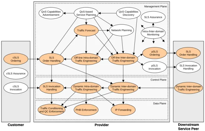
Deliverable D1.2 describes the overall MESCAL functional architecture and specifies algorithms and protocols for each of the main functional components. Figure 1 highlights those aspects of functional architecture that are subject to experimentation and therefore implementation within the project.
QoS-based Service Planning QoS Capabilities Advertisement QoS Capabilities Discovery
Traffic Forecast Network Planning
Off-line Inter-domain Traffic Engineering Dynamic Inter-domain Traffic Engineering Off-line Intra-domain Traffic Engineering Dynamic Intra-domain Traffic Engineering SLS Invocation Handling SLS Order Handling pSLS Ordering pSLS Invocation IP Forwarding PHB Enforcement Traffic Conditioning and QC Enforcement SLS Assurance cSLS Ordering cSLS Invocation Customer Provider Data Plane Control Plane Management Plane cSLS Assurance SLS Order Handling SLS Invocation Handling Dynamic Inter-domain Traffic Engineering Downstream Service Peer Intra-/Inter-domain Monitoring QoS-based Service Planning QoS Capabilities Advertisement QoS Capabilities Discovery
Traffic Forecast Network Planning
Off-line Inter-domain Traffic Engineering Dynamic Inter-domain Traffic Engineering Off-line Intra-domain Traffic Engineering Dynamic Intra-domain Traffic Engineering SLS Invocation Handling SLS Order Handling pSLS Ordering pSLS Invocation IP Forwarding PHB Enforcement Traffic Conditioning and QC Enforcement SLS Assurance cSLS Ordering cSLS Invocation Customer Provider Data Plane Control Plane Management Plane cSLS Assurance SLS Order Handling SLS Invocation Handling Dynamic Inter-domain Traffic Engineering Downstream Service Peer Intra-/Inter-domain Monitoring
Figure 1 MESCAL functional architecture, highlighting the components to be implemented Each of the functional components is further decomposed into the engineering components to be implemented in order to test the algorithms and protocols specified by the project. The implementation tasks may be classified as follows:
• Development of the testbed network: tasks related to the deployment of the QoS capabilities required in the control and data plane of Linux routers within the project testbed.
• Development of the simulated network: tasks related to the development of the required control and data plane QoS capabilities in the simulators.
• Development of the MESCAL management plane: the off-line traffic engineering and SLS management algorithms and protocols. These components are to be tested in two modes: to assess their validity and performance with regard to the static aspects of network operation without being integrated with control/data planes of either the testbed or simulated network; and, subsequently, selected groups of functions will be integrated with the testbed and/or network simulators to assess their validity in dynamic network environments.
In addition to the engineering counterparts of the functional model, a set of adaptors are required to interface the management plane components with the testbed and/or simulators and, furthermore, a set of experimentation tools, such as traffic generators and results analysis applications are required to assist the testing activities of WP3.
Given the experimentation objectives highlighted in the previous section and the implementation categories introduced above we have identified the following implementation tasks for WP2.
Traffic Engineering implementation tasks:
• Off-line inter-domain TE
• Binding selection
• Binding activation
• Inter-domain resource optimisation
• Off-line multicast TE
• Path computation algorithm
• PCS interactions
• Off-line intra-domain TE
• Network reconfiguration scheduler
• Intra-domain resource optimisation
• Off-line multicast TE
• Dynamic inter-domain TE
• qRIB
• qBGP interactions
• Route selection
• Dynamic intra-domain TE (IGP extensions)
• Network repository Data plane implementation tasks:
• Traffic conditioning
• PHB enforcement
• IP forwarding/qFIB
SLS management implementation tasks:
• cSLS ordering
• pSLS ordering
• SLS order handling
• SLS repository
• SLS-based demand derivation tools (traffic forecast)
• SLS invocation handling
Adaptors to testbed/simulation environment
• SLS management -> testbed
• Off-line inter-domain TE -> testbed
• SLS management -> Off-line intra- and inter-domain TE (traffic forecast)
• Off-line inter-domain TE -> Off-line intra-domain TE (traffic forecast)
• Off-line inter-domain TE -> Dynamic inter-domain TE (qBGP)
• Multicast TE -> network simulator Experimentation tools
• Traffic generation tools
• Bulk c/pSLS order emulator
• Network topology generator
• Results analysis tools
A software engineering design for all of the identified components will be specified in I2.2, Detailed implementation design of components for inter-domain, QoS-based service management, network design, dynamic resource management and routing, due in month 16 of the project.
2.3
Implementation plan
2.3.1
Effort plan
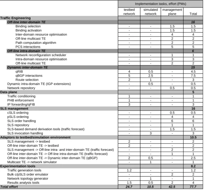
As estimation of the effort required for the detailed engineering design, software coding and stand-alone testing of each component is presented in Table 1.
testbed network simulated network management plane Total Traffic Engineering Off-line inter-domain TE 16 Binding selection - - 1.5 1.5 Binding activation - - 1.5 1.5
Inter-domain resource optimisation - - 4 4
Off-line multicast TE - - 2 2
Path computation algorithm - - 2 2
PCS interactions - - 5 5
Off-line intra-domain TE 6
Network reconfiguration scheduler - - 1 1
Intra-domain resource optimisation - - 3 3
Off-line multicast TE - - 2 2
Dynamic inter-domain TE 15
qRIB 4 0.5 - 4.5
qBGP interactions 5 2.5 - 7.5
Route selection 2 1 - 3
Dynamic intra-domain TE (IGP extensions) - 0.5 - 0.5
Network repository - - 0.5 0.5 Data plane 5 Traffic conditioning 1 - - 1 PHB enforcement 1 - - 1 IP forwarding/qFIB 3 - - 3 SLS management 16 cSLS ordering - - 0.5 0.5 pSLS ordering - - 4 4 SLS order handling - - 6 6 SLS repository - - 1 1
SLS-based demand derivation tools (traffic forecast) - - 1.5 1.5
SLS invocation handling - 3 - 3
Adaptors to testbed/simulation environment 10.5
SLS management -> testbed 2 - - 2
Off-line inter-domain TE -> testbed 2 - - 2
SLS management -> Off-line intra- and inter-domain TE (traffic forecast) - - 2 2 Off-line inter-domain TE -> Off-line intra-domain TE (traffic forecast) - - 1 1
Off-line inter-domain TE -> Dynamic inter-domain TE (qBGP) 2 0.5 - 2.5
Multicast TE -> network simulator - 1 - 1
Experimentation tools 8.2
Traffic generation tools 1.2 - - 1.2
Bulk c/pSLS order emulator - - 2 2
Network topology generator - 1 - 1
Results analysis tools 1.5 0.5 2 4
Total effort 24.7 10.5 42.5 77.7
Implementation tasks, effort (PMs)
Table 1 Implementation tasks and estimation of development effort
It should be noted that some of the implementation tasks are already underway and effort has already been consumed. The figures presented in the table above refer only to the remaining effort required, as of the end of January 2004.
2.3.2
Implementation schedule
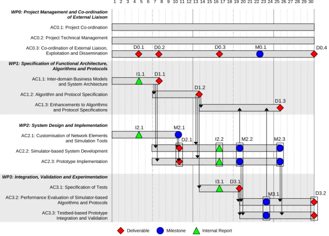
The overall project Gantt chart is shown in Figure 2. This shows the relationships between WP2 and WP3 and the overall schedule in time.
WP0: Project Management and Co-ordination of External Liaison
AC0.1: Project Co-ordination
AC0.2: Project Technical Management
AC0.3: Co-ordination of External Liaison, Exploitation and Dissemination
WP1: Specification of Functional Architecture, Algorithms and Protocols
AC1.1: Inter-domain Business Models and System Architecture
AC1.2: Algorithm and Protocol Specification
AC1.3: Enhancements to Algorithms and Protocol Specifications
WP2: System Design and Implementation
AC2.1: Customisation of Network Elements and Simulation Tools
AC2.2: Simulator-based System Development
AC2.3: Prototype Implementation
WP3: Integration, Validation and Experimentation
AC3.1: Specification of Tests
AC3.2: Performance Evaluation of Simulator-based Algorithms and Protocols
AC3.3: Testbed-based Prototype Integration and Validation
D1.1 D1.2 D1.3 D0.1 D0.3 D0.4 D2.1 M2.1 I2.2 M2.2 M2.3 D3.1 I3.1 D3.2 M3.1 M0.1
Deliverable Milestone Internal Report
1 2 3 4 5 6 7 8 9 10 11 12 13 14 15 16 17 18 19 20 21 2223 24252627282930
D0.2
I1.1
I2.1
Figure 2 Project Gantt chart: overall schedule of work
An indicative milestone, M2.2, was placed at month 19 (May 2005) to show that WP2 software releases would be made before the end of the activities of the workpackage. This was included to allow experimentation to begin on initial aspects of the MESCAL solutions and to enable feedback from this preliminary experimentation work to influence algorithm and protocol revisions in WP1 and the implementation of refined components in WP2. The following section refines this initial view by identifying a more detailed set of milestones for software releases, according to experimentation plans.
2.3.2.1
Milestones
WP3 is currently defining the experimentation plans of the project and has identified the following sets of tests together with the dates they should commence. The precise schedule of the tests is to be specified in detail in the experimentation plan in deliverable D3.1.
Testbed-based tests (refer to section 3 for an overview of the objectives and scope of each phase):
• phase 1, initial validate the deployment of the loose solution option: April 2004
• phase 2, validation of the q-BGP: September 2004
• phase 3, validation of the path computation approach for the hard service option: November 2004
• phase 2bis (optional): from February 2005
• SLS Management configuration of testbed
• Off-line Inter-domain TE configuration of testbed
Simulator-based tests (refer to section 4 for an overview of the objectives and scope of each phase and a more detailed schedule of evaluation tests per subcomponent):
A. static network simulation environments:
• Off-line Inter-domain TE: Binding Activation evaluation from April 2004, Binding Selection evaluation from July 2004, Resource Optimisation from August 2004, and integrated tests from October 2004.
• Off-line Intra-domain TE: Resource Optimisation evaluation from July 2004, Resource reconfiguration scheduling from September 2004, integrated tests from January 2005.
• Off-line Intra- and Inter-domain TE interworking: January 2005
• SrNP (pSLS Ordering/Order Handling): September 2004 B. dynamic network simulation environments:
• qBGP: August 2004
• SLS invocation handling: intra-domain tests from April 2004, inter-domain tests from July 2004.
• Multicast: phase one from April 2004, intra-domain evaluation from August 2004 and inter-domain evaluation from December 2004.
• Off-line Inter-domain TE and qBGP interworking: January 2005
• Off-line Intra-domain TE and qIGP interworking: January 2005
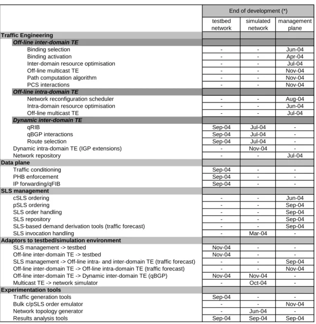
In order to achieve these milestones the implementation tasks have been scheduled to complete by the dates shown in Table 2. It should be noted that many of the implementation activities are due to have several phases. The table specifies the dates of the initial releases of the components. Refer to sections 3 and 4 for more details and a detailed gantt chart of the implementation tasks is due to be produced in I2.2, in month 16.
2.3.3
Allocation of tasks to partners
The final part of the implementation plan is the distribution of development activities between the project partners. This is shown in Table 3 together with the effort allocated to each partner for each task.
testbed network simulated network management plane Traffic Engineering Off-line inter-domain TE
Binding selection - - Jun-04
Binding activation - - Apr-04
Inter-domain resource optimisation - - Jul-04
Off-line multicast TE - - Nov-04
Path computation algorithm - - Nov-04
PCS interactions - - Nov-04
Off-line intra-domain TE
Network reconfiguration scheduler - - Aug-04
Intra-domain resource optimisation - - Jun-04
Off-line multicast TE - - Jul-04
Dynamic inter-domain TE
qRIB Sep-04 Jul-04
-qBGP interactions Sep-04 Jul-04
-Route selection Sep-04 Jul-04
-Dynamic intra-domain TE (IGP extensions) - Nov-04
-Network repository - - Jul-04
Data plane
Traffic conditioning Sep-04 -
-PHB enforcement Sep-04 -
-IP forwarding/qFIB Sep-04 -
-SLS management
cSLS ordering - - Jun-04
pSLS ordering - - Sep-04
SLS order handling - - Sep-04
SLS repository - - Sep-04
SLS-based demand derivation tools (traffic forecast) - - Sep-04
SLS invocation handling - Mar-04
-Adaptors to testbed/simulation environment
SLS management -> testbed Nov-04 -
-Off-line inter-domain TE -> testbed Nov-04 -
-SLS management -> Off-line intra- and inter-domain TE (traffic forecast) - - Sep-04 Off-line inter-domain TE -> Off-line intra-domain TE (traffic forecast) - - Nov-04 Off-line inter-domain TE -> Dynamic inter-domain TE (qBGP) Nov-04 Nov-04
-Multicast TE -> network simulator - Oct-04
-Experimentation tools
Traffic generation tools Sep-04 -
-Bulk c/pSLS order emulator - - Nov-04
Network topology generator - Jun-04
-Results analysis tools Sep-04 Sep-04 Sep-04
End of development (*)
FTRD TRT UCL UniS Algo Total Traffic Engineering
Off-line inter-domain TE
Binding selection - - - 1.5 - 1.5
Binding activation - - - 1.5 - 1.5
Inter-domain resource optimisation - - - 4 - 4
Off-line multicast TE - - - 2 - 2
Path computation algorithm 2 - - - - 2
PCS interactions 5 - - - - 5
Off-line intra-domain TE
Network reconfiguration scheduler - - 1 - - 1
Intra-domain resource optimisation - - 3 - - 3
Off-line multicast TE - - - 2 - 2
Dynamic inter-domain TE
qRIB 3 1 0.5 - - 4.5
qBGP interactions 5 - 2.5 - - 7.5
Route selection 2 - 1 - - 3
Dynamic intra-domain TE (IGP extensions) - - 0.5 - - 0.5
Network repository - - 0.5 - - 0.5 Data plane Traffic conditioning - 1 - - - 1 PHB enforcement - 1 - - - 1 IP forwarding/qFIB 2 1 - - - 3 SLS management cSLS ordering - - - - 0.5 0.5 pSLS ordering - - - - 4 4 SLS order handling - - - - 6 6 SLS repository - - - - 1 1
SLS-based demand derivation tools (traffic forecast) - - - - 1.5 1.5
SLS invocation handling - - - 3 - 3
Adaptors to testbed/simulation environment
SLS management -> testbed - 2 - - - 2
Off-line inter-domain TE -> testbed - 2 - - - 2
SLS management -> Off-line intra- and inter-domain TE (traffic forecast) - - - - 2 2 Off-line inter-domain TE -> Off-line intra-domain TE (traffic forecast) - - - - 1 1
Off-line inter-domain TE -> Dynamic inter-domain TE (qBGP) - 2 0.5 - - 2.5
Multicast TE -> network simulator - - - 1 - 1
Experimentation tools
Traffic generation tools - 1.2 - - - 1.2
Bulk c/pSLS order emulator - - - - 2 2
Network topology generator - - 1 - - 1
Results analysis tools - 1.5 0.5 - 2 4
Total effort 19 12.7 11 15 20 77.7
3
OVERVIEW OF TESTBED-BASED IMPLEMENTATION
ACTIVITIES
One of the major objectives of the MESCAL project is to develop and evaluate the concepts, the algorithms and the architecture that have been specified by the project for deploying an end-to-end QoS delivery chain. These specifications are/will be the subject of several MESCAL deliverables, especially [D1.1], [D1.2] and [D1.3].
In order to achieve this goal and to better control implementation risks, the MESCAL testbed implementation plan introduces progressive implementation phases and milestones for the development of a "proof of concept"-oriented testbed.
Three phases have been defined. Each phase has been hereafter described in terms of:
• Objectives;
• Functional blocks it will impact;
• Milestone resulting of its completion.
MESCAL testbed will not implement the whole MESCAL functional system, but will focus on some key aspects of the MESCAL specifications. Some functional blocks will be implemented completely and others partially. Some blocks will be used without modifying the native behaviour of existent implementations. In this respect, all functional blocks impacted by the implementation phase have been assigned a colour reflecting the importance of the modifications to make. Three levels of modification have been introduced as described below:
• Green: no modifications will be made to the current behaviour of the functional block for the related phase.
• Yellow: the output of this block is mandatory but will not be implemented. Only emulation or partial implementation will be made for the related phase.
• Red: all necessary modifications will be made to the functional block for the related phase.
The testbed will be located in the FTR&D premises. Further information about the configuration and the set up of this testbed will be provided by WP3 in internal report I3.1, Definition of testbed infrastructure for prototype integration and validation, due in month 16 and in deliverable D3.1, Specification of test campaigns and experimentation plans for performance analysis and prototype validation, due in month 19.
3.1.1
Phase 1
3.1.1.1
Goals
The objective of this first phase is to validate the deployment of the loose solution option in a very simple context. This will allow to validate the meta-QoS-class approach, the architecture of the testbed, and to qualify tools and functions (shaping, forwarding, routing, DSCP marking) embedded in Linux routers.
In order to achieve this goal it will be necessary to:
• Deploy an experimental testbed including several ASs exchanging inter-domain routing information between them. This step consists mainly in:
• Building an experimental testbed made of several autonomous systems.
• Running and configuring BGP (Border Gateway Protocol) between ASs
• Running and configuring intra-domain routing protocols (OSPF for instance)
• Defining QoS classes (l-QC) for each AS configured in the previous step
• Classify these l-QCs with regard the meta-QoS-class paradigm
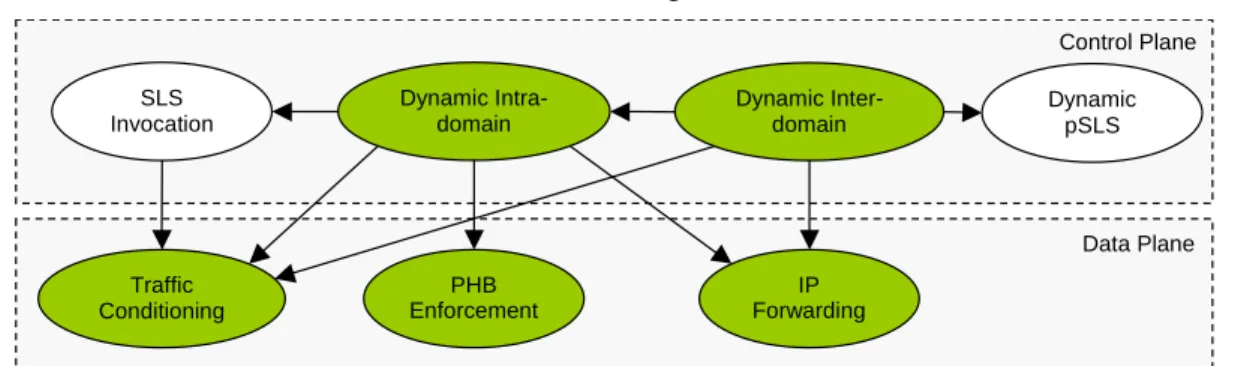
This phase will not alter or create any of the MESCAL functional blocks. In particular, no QoS information will be carried in the BGP UPDATE messages.
Dynamic Inter-domain Dynamic Intra-domain SLS Invocation Dynamic pSLS IP Forwarding PHB Enforcement Traffic Conditioning Data Plane Control Plane
Figure 3 Overview of the functional blocks involved in phase 1 As shown in the figure above, the functional blocks involved within this phase are:
• Dynamic domain: within the context of MESCAL we will use the OSPF protocol as an intra-domain routing protocol with TE extensions [OSPF-TE].
• Dynamic inter-domain: the BGP-v4 will be used as an inter-domain routing protocol.
• Traffic conditioning and PHB Enforcement:
The ZeboS Routing Suite (version 5.3 or latter) will be the base routing stack activated on the Linux routers. Linux Network control Traffic will be used to configure QoS functions in Linux routers.
3.1.1.2
Milestone
Experimentation for this phase will begin in April 2004.
3.1.2
Phase 2
3.1.2.1
Goals
The objectives of this phase are to validate the q-BGP (both q-eBGP and q-iBGP) specification together with the IP forwarding for the loose solution option and to make available a demonstration platform on which phase 3 will rely on. This phase will be the basis of q-BGP functional test campaigns that will aim to validate the q-BGP specifications and check if the MESCAL requirements were met. In addition, interoperability tests will also been achieved within this phase, especially to check if a non q-BGP-enabled router will treat a q-BGP message and vice versa. For this aim, we will make use of traffic generators and embed in the platform non q-BGP-enabled routers.
In order to achieve this goal the following will be achieved:
• Implement a QoS-inferred BGP protocol (q-BGP). This will mainly consists in:
• Implementing the "QOS_NLRI" and the "QoS Service Capability" attributes.
• Modifying the BGP route selection process in order to take into account the QoS performance characteristics.
• Modify the forwarding functional block so that IP forwarding can be made on a per DSCP-plane basis, each DSCP plane representing a particular Meta-QoS-Class.
• Activate q-BGP as an inter-domain routing protocol in the testbed deployed within the phase 1. This step will consist mainly in running and configuring the above-developed q-BGP in the testbed.
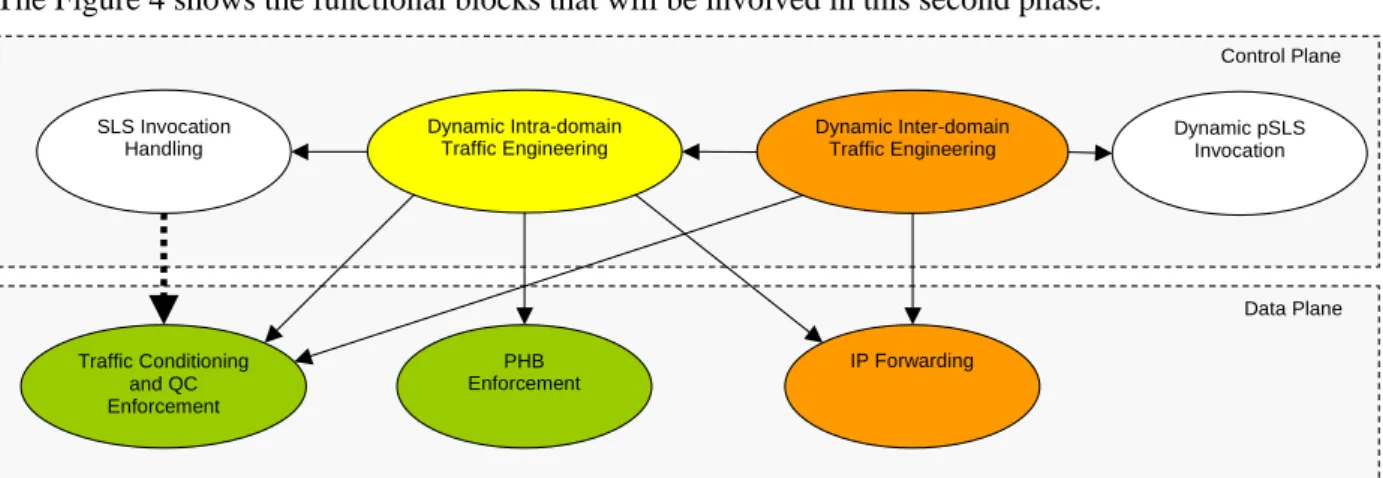
The Figure 4 shows the functional blocks that will be involved in this second phase.
Dynamic Inter-domain Traffic Engineering Dynamic Intra-domain Traffic Engineering SLS Invocation Handling Dynamic pSLS Invocation IP Forwarding PHB Enforcement Traffic Conditioning and QC Enforcement Data Plane Control Plane
Figure 4 Overview of the functional blocks involved in phase 2
The dynamic inter-domain traffic engineering should take into account the QoS information. The routing selection process should be QoS-based.
For these developments we will make use of the ZeboS Routing Suite (version 5.3 or latter). This suite, once modified, will provide enhanced inter-domain routing capabilities and will be activated on top of Linux routers. Developments of the enhanced IP forwarding functional block will rely on Linux kernel (the latest stable version is 2.6.1).
This phase aims also to validate if the control plane can enforce decisions made by the offline TE blocks. The communication at the interface between the two layers will be achieved manually.
Completion of this phase will lead to the availability of an experimental loose solution option implementation, which in itself will allow validating some of the key MESCAL concepts.
3.1.2.2
Milestones
Implementation for this phase is due to be completed by September 2004.
3.1.3
Phase 3
3.1.3.1
Goals
The objective of this phase is to validate the path computation approach for the hard service option with the aim of building end-to-end inter-domain LSPs. More particularly, this phase will allow validating the interaction between the path computation process and q-BGP and also the pertinence of using QoS information learned by this way.
In order to achieve this goal, MESCAL will:
• Implement PCS: this step focuses on the implementation of a centralized entity that will be developed to build end-to-end LSP.
• Implement the PCS Communication Protocol (PCP): this protocol is the communication protocol used between PCS and will be developed in Java or C/C++.
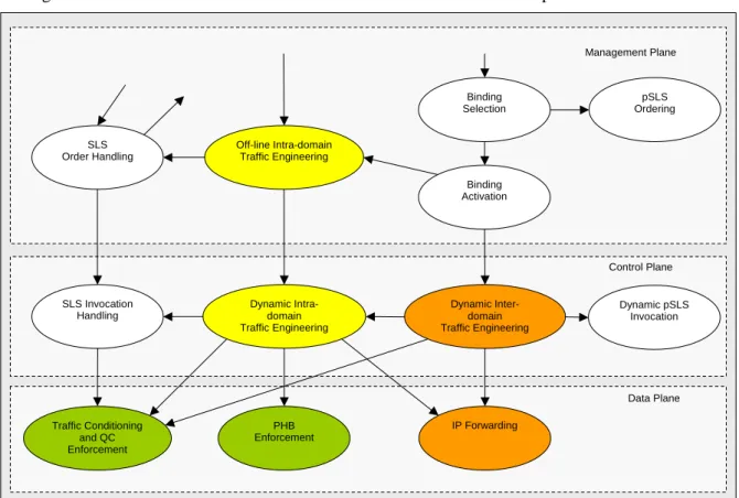
The Figure 5 shows the functional blocks that will be involved in this third phase. Binding Selection Binding Activation Dynamic Inter-domain Traffic Engineering Off-line Intra-domain Traffic Engineering Dynamic Intra-domain Traffic Engineering SLS Invocation Handling SLS Order Handling pSLS Ordering Dynamic pSLS Invocation IP Forwarding PHB Enforcement Traffic Conditioning and QC Enforcement Data Plane Control Plane Management Plane
Figure 5 Overview of the functional blocks involved in phase 3
Within this phase, we will implement the hard solution option above the loose solution option (except some enhanced management functions). The establishment of inter-domain LSPs will be initiated by PCSs. Cisco routers will be integrated in this phase when required IOS features are available.
During this phase, we will make use of RSVP-TE that will be used for requesting the creation of LSPs. Intra-domain routing (like OSPF-TE) will be used to find available routes when creation of loose LSP is requested by the PCS.
3.1.3.2
Milestones
4
OVERVIEW OF SIMULATION-BASED
IMPLEMENTATION ACTIVITIES
4.1
SLS Invocation Handling (Admission Control)
4.1.1.1
Objectives
SLS Invocation Handling is an online component that is responsible for controlling the amount of traffic injected into the network so that conformant users achieve predefined performance objectives, as these are specified in the SLSs. The term ‘users’ can correspond to either individual customers, e.g. home users, universities, organizations, or to entire ISP domains. In the former case, cSLSs describe the required performance guarantees, whereas in the latter case, pSLSs describe the required traffic treatment.
4.1.1.2
Design
In order to evaluate SLS invocation handling algorithms, packet-level simulations are required for a variety of real-time and elastic applications and for aggregated streams composed by individual applications. The network simulator (ns-2) will be used for all simulations, since it is a free available packet-level simulator that supports a variety of applications and can be extended to support additional applications if needed. The simulations will first focus on validating algorithms for intra-domain SLS invocation handling and will then focus on the inter-domain case.
4.1.1.3
Interworking
All components needed for simulating the developed SLS invocation handling algorithms will be implemented as standalone oTCL scripts (oTCL is the interface language of ns-2) and additional functions –if needed- will be implemented in C++ code as extensions to the existing ns-2 C++ code.
4.1.1.4
Time Plan
The time plan includes both intra-domain and inter-domain phases.
Phase Start date End date
Intra-domain SLS Invocation Handling: customisation / development
November 2003 March 2004 Intra-domain SLS Invocation Handling:
evaluation
April 2004 July 2004 Inter-domain SLS Invocation Handling:
customisation / development
March 2004 June 2004 Inter-domain SLS Invocation Handling:
evaluation
July 2004 October 2004
4.1.2
Offline Inter-domain TE: Binding Selection
4.1.2.1
Objectives
Binding Selection is an offline component that is responsible for selecting e-QC bindings and deciding which pSLSs need to be ordered, modified and ceased in order to meet the inter-domain QoS requirements of the predicted traffic. A principal interface of Binding Selection is with Inter-domain Resource Optimisation (Section 4.1.4). The Binding Selection simulator will implement the algorithms defined in [D1.2]. Since Binding Selection is conducted based on flows (as defined in the
external traffic matrix, eTM), packet-level simulation is not required. MESCAL will consequently develop its own simulation software based on C/C++/Java.
4.1.2.2
Design
The simulator will contain the following modules:
• Pre-processor scenario generator: inter-domain traffic generator (e-TM); network topology generator; e-QC, l-QC and o-QC scenario generator (this module will be a programmable mix of hardcoded values and algorithmic generators for volume testing);
• QC Mapping algorithms: generate e-QC lists based on l-QC and o-QC inputs as described in [D1.2] Section 5.2.1.
• Binding Selection algorithms: perform preliminary sorting and reduction of l-QC and o-QC options, using algorithms defined in [D1.2] Section 5.2.2, in particular by calling Inter-domain Resource Optimisation.
The simulation software will be written in C, C++ or Java.
4.1.2.3
Interworking
Input interfaces
The Binding Selection simulation will take input data, as follows:
• From QoS Capabilities Discovery function block: a list of o-QCs offered by peer domains;
• From QoS-based Service Planning function block: a list of e-QCs that the domain is required to offer (as defined by its business related activities and objectives); and a list of l-QCs that the domain will support internally;
• From TF: the external traffic matrix (eTM).
Since no simulations or implementations of these function blocks are planned, the “scenario generator” module will generate these input data.
Interfaces to Inter-domain Resource Optimisation and Binding Activation
Inter-domain Resource Optimisation will be called to map the inter-domain eTM to the inter-domain traffic matrix.
The output from the Binding Selection simulator will be a set of bindings, in flat file format. The format of these bindings will be such that the file can be used as input to the Binding Activation simulation.
4.1.2.4
Time plan
The Binding Selection simulator software will be released as a single Phase. A second Phase is included to reflect any design amendments that may be produced following the release of [D1.3].
Phase Start date End date
Binding Selection Phase 1: development February 2004 June 2004 Binding Selection Phase 1: evaluation July 2004 September 2004 Binding Selection Phase 2: D1.3
development updates
September 2004 October 2004 Binding Selection Phase 2: D1.3 evaluation November 2004 January 2005
4.1.3
Offline Inter-domain TE: Binding Activation
4.1.3.1
Objectives
Binding Activation is an offline component that is responsible for mapping the predicted external (inter-domain) traffic matrix to the inter-domain network resources, satisfying QoS requirements while aiming at optimising the use of network resources across AS boundaries. A principal interface of Binding Activation is with Inter-domain Resource Optimisation (Section 4.1.4). This simulator will implement the algorithms defined in [D1.2]. Binding Activation is done at flow-level; hence its simulation only requires flow-level measurements. This implies that packet-level simulations can be eliminated. To validate and evaluate algorithms for Binding Activation, MESCAL will consequently develop its own simulator without relying on any existing software packages.
4.1.3.2
Design
The simulation software includes the following modules:
• Inter-domain traffic generator (eTM) (this will use the same software as Binding Selection);
• Network topology generator (may use existing tools) (this again will use the same software as Binding Selection);
• Retrieval of Binding Selection results;
• Implementation of binding activation algorithms.
The simulator will be implemented by means of programming languages such as C/C++ or Java.
4.1.3.3
Interworking
Interface 1
Inter-domain traffic and network topologies are generated as output files, using the same software as Binding Selection. These output files are then taken by the Binding Activation algorithm module, together with the Binding Selection results, as input to perform inter-domain traffic engineering. Interface 2
The Inter-domain Resource Optimisation algorithm module provides an interface to accept a function call from the Binding Activation algorithm module to start inter-domain routing and traffic engineering. The Binding Activation algorithm module also provides an interface to accept results from the Inter-domain Resource Optimisation algorithm module.
4.1.3.4
Time Plan
The Binding Activation simulator software will be released as a single Phase. A second Phase is included to reflect any design amendments that may be produced following the release of [D1.3].
Phase Start date End date
Binding Activation: Phase 1 development November 2003 April 2004 Binding Activation: Phase 1 evaluation April 2004 July 2004 Binding Activation: Phase 2 D1.3
development
July 2004 September 2004 Binding Activation: Phase 2 D1.3
evaluation
4.1.4
Offline Inter-domain TE: Resource Optimisation
4.1.4.1
Objectives
Inter-domain Resource Optimisation is an offline component that is responsible for computing an optimal inter-domain traffic engineering solution; it achieves this based on predicted inter-domain traffic (held in the eTM) and inter-/intra-domain resources. The Inter-domain Resource Optimisation simulator will implement the algorithms defined in [D1.2]. In common with the Binding Selection and Binding Activation simulators, the algorithms are based on traffic flows and so packet-level simulation is not required. MESCAL will consequently implement its own software for this simulator.
4.1.4.2
Design
The simulation software includes the following modules:
• Input and validation from Binding Selection / Binding Activation;
• Implementation of Resource Optimisation algorithms. In D1.2, a number of algorithms are defined (random assignment, brute force, genetic algorithm, and custom heuristic), and separate software modules will be written for each algorithms;
• Stub intra-domain traffic engineering algorithm (see below).
4.1.4.3
Interworking
Inter-domain Resource Optimisation will be called by both the Binding Selection and Binding Activation modules, and will return the Inter-domain cost and configuration information.
In a full implementation of MESCAL, Inter-domain Resource Optimisation would interface with Offline Intra-domain Traffic Engineering. For the simulation however we do not intend to simulate the intra-domain functionality. Consequently, we will build a stub software component that will assign intra-domain traffic flows using a simple algorithm such as CSPF and perform a simple (not optimised) calculation of the intra-domain cost Φ.
4.1.4.4
Time plan
The Inter-domain Resource Optimisation simulator software will be released as a single Phase, but with code for each algorithm staggered. A second Phase is included to reflect any design amendments that may be produced following the release of [D1.3].
Phase Start date End date
Resource Optimisation: Phase 1 development
March 2004 July 2004
Resource Optimisation: Phase 1 evaluation August 2004 October 2004 Resource Optimisation: Phase 2: D1.3
development
October 2004 December 2004 Resource Optimisation: Phase 2: D1.3
evaluation
4.1.5
Offline Intra-domain TE: Resource Optimisation
4.1.5.1
Objectives
Resource Optimisation is the Intra-domain TE component responsible for computing OSPF link weights based on traffic forecast demand matrices. The simulations should serve as a proof of concept as well as giving insight into the following questions,
• Algorithm stability and convergence time
• Algorithm scalability: dependence on network size and number of DSCP routing planes In addition the simulations should allow quantification of cost functions responsible for algorithm convergence, QoS constraints and intra/inter-domain optimisations. (For further details on test requirements refer to relevant sections in D1.2)
4.1.5.2
Design
The simulator will contain the following modules:
• Scenario generator: intra-domain traffic generator (i-TM); network topology generator
• Resource Optimisation algorithm [D1.2] will be implemented in the several steps
o Initial algorithm comprising all essential features
o Advanced features such as cost functions for convergence and termination and Techniques for few weight changes
The simulation software will be written in C, C++ or Java.
4.1.5.3
Interworking
The Resource Optimisation block has only one interface. It is controlled by the Network Reconfiguration Scheduler. This interface is used to signal requests for resource optimisation and passes a handle to all necessary information, such as an iTM, which can then be retrieved from a database. The return value to a resource optimisation request is a handle to the location of the resulting link weight matrix.
4.1.5.4
Time plan
Resource Optimisation will be implemented in two phases, the initial version of the algorithms as specified in D1.2 and a second phase reflecting any evolution of the algorithms arising from a more in depth understanding gained during the first phase.
Phase Start date End date
Phase 1: Development February 2004 June 2004
Phase 1: Evaluation July 2004 September 2004
Phase 2: D1.3 Development Enhancements September 2004 November 2004 Phase 2: D1.3 Evaluation of Enhancements December 2004 March 2005
4.1.6
Offline Intra-domain TE: Network Reconfiguration Scheduler
4.1.6.1
Objectives
The Network Reconfiguration Scheduler is the control system component for Intra-domain TE. The simulator will act as supporting measure to the simulation of Resource Optimisation. Network Reconfiguration Scheduler will be responsible for implementing link weights into the network
simulator. It will also contain the scheduler described in D1.2. It is responsible for implementing pre-computed scenarios for network re-optimisation, when it detects (or is notified) that an optimisation is required. Simulations should therefore give insight into the feasibility of the scheduler regarding
• Correct identification of the network state
• Correct selection of pre-computed weight settings
• Disruptiveness of few weight changes compared to a less optimal network (For further details on test requirements refer to relevant sections in D1.2)
4.1.6.2
Design
The simulation of the Network Reconfiguration Scheduler consist of the following components.
• Front-end processes required for Resource Optimisation such as handling requests for computation
• Scheduler functionality including
o Periodic network optimisation
o Disaster recovery schedules e.g. link failures, etc.
• Retrieving weight settings for scenarios and implementing them via Dynamic Intra-domain TE
The simulator will be implemented by means of programming languages such as C/C++ or Java.
4.1.6.3
Interworking
Network Reconfiguration Scheduler is the front-end process to the Intra-domain TE. It therefore has several interfaces.
• Resource Optimisation, initiate Network Optimisation and store handles to results
• Inter-domain Resource Optimisation provides the location to iTM’ hypothetical traffic demand matrices for “what-if” scenarios, Network Reconfiguration Scheduler returns handles to iRAM and cost function value
• Network Reconfiguration Scheduler provides the iRAM to the SLS Order Handling
• Network Reconfiguration Scheduler configures Dynamic Intra-domain TE inside the network layer to configure weight settings, Equal Cost Multi Path (ECMP) settings, etc. It receives alerts for events such as link failures.
Since the Traffic Forecast component will not be implemented, iTM and iTM’ traffic matrices will have to be generated using the traffic generators planned in section 4.1.5.2 or as part of the Inter-domain TE components.
4.1.6.4
Time Plan
Network Reconfiguration Scheduler will be implemented in two phases, the initial version of the algorithms as specified in D1.2 and a second phase reflecting any evolution of the algorithms arising from a more in depth understanding gained during the first phase. It is expected that the component will be lagging the development of Resource Optimisation, as it is effectively only the front-end to Resource Optimisation and therefore cannot be evaluated by itself.
Phase Start date End date
Phase 1 development June 2003 August 2004
Phase 1 evaluation September 2004 October 2004
Phase 2 D1.3 development October 2004 December 2004
4.1.7
Multicast
4.1.7.1
Objectives
This objective of this simulation part is to study the empirical performance of the proposed algorithms for QoS multicast routing as well as Intra- and Inter-domain multicast traffic engineering.
4.1.7.2
Design
The simulation task of multicast can be divided into two parts, namely packet level simulation and network level simulation.
The packet level simulation will investigate the impact on multicast packets of different policies for PHB enforcement. The construction of per-PHB trees or hybrid trees results in different end-to-end QoS performance (delay, delay variation, loss probability etc.). This is because, in the former approach packets with different QC requirements are treated with a unified PHB in separate trees, while the latter approach allows multicast packets with lower QC requirements to be treated with higher PHB classes where there exists common path for the traffic coming from the same group. The objective of this simulation is to evaluate the end-to-end QoS difference between the two approaches, and typically to investigate the fairness issue among packet treatments with different PHBs. Hence packet-level based simulators, such as ns-2, will be used in this part of simulation.
The network level based simulation will target intra- and inter-domain multicast traffic engineering aspects. Constraint-based routing is a major solution for achieving efficient traffic engineering, and typically optimised multicast routing can be formulated into the Steiner tree problem, which is NP-complete. Hence most of the further multicast TE approaches (typically routing algorithms) will be evolved from this graph theory problem. Taking this fact into account, the relevant simulation analysis can be achieved through standalone programming. On the other hand, some existing tools can support this type of simulation very well, such as Stanford Graph Base (SGB), and it will be considered as a potential tool for the simulation part at the network level.
4.1.7.3
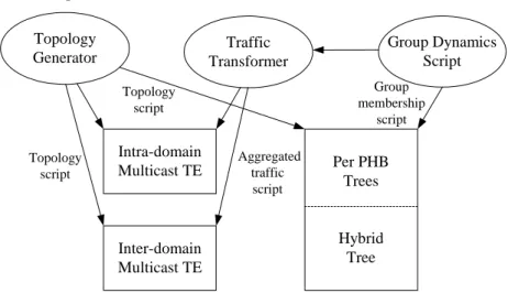
Interworking
Topology Generator Traffic Transformer Group Dynamics Script Intra-domain Multicast TE Inter-domain Multicast TE Per PHB Trees Hybrid Tree Topology script Topology script Aggregated traffic script Group membership script4.1.7.4
Time Plan
Phase Start date End date
Multicast Phase 1: End-to-end QoS comparison between hybrid tree vs. per PHB tree (using ns-2) – development
December 2003 March 2004
Multicast Phase 1: ns-2 - evaluation April 2004 June 2004 Multicast Phase 2: Intra-domain Multicast TE
(standalone) - development
May2004 July 2004
Multicast Phase 2: Intra-domain - evaluation August 2004 October 2004 Multicast Phase 3: Inter-domain Multicast TE
(standalone) – development
September 2004 November 2004 Multicast Phase 3: Inter-domain - evaluation December 2004 February 2005
4.1.8
qBGP simulation
4.1.8.1
Objectives
qBGP is the extension of the current inter-domain routing protocol, BGP, to convey QoS capability between domains. However, adding QoS extensions to BGP may cause instability and scalability problems. Therefore, qBGP will need to be carefully designed to minimize the occurrence or the adverse effects of these problems.
It is necessary to understand the potential impact of new features and extensions as they are added to the BGP. Thus, having sound simulators to evaluate qBGP is crucial. Currently, there are a number of simulators supporting BGP implementation but some of them have not been extensive used and evaluated. Among a number of potential choices, discussed in the simulator section, SSFNET seems the most appropriate simulator for qBGP evaluation. The effort needed to implement qBGP on SSFNET is estimated to be the same compared to the other simulators, while additionally SSFNET has a an existing full BGP implementation, which is well verified and widely used.
4.1.8.2
Design
The qBGP simulation will include the following modules:
• qBGP implementation (BGP extended in accordance with [D1.2]);
• Module for generation of AS-level topologies and inter-domain traffic;
• Module to generate dynamic behaviours, e.g. change of available bandwidth to invoke new BGP advertisements, etc.
4.1.8.3
Inter-working
AS-level topologies and inter-domain traffic are generated as files. These files are then used by the qBGP implementation module as the basis to start the simulations.
The qBGP implementation provides an interface to dynamically accept qBGP advertisements generated by the dynamic behaviours generation module; these advertisements are then propagated by qBGP.
4.1.8.4
Time Plan
Phase Start date End date
qBGP: development May 2004 July 2004