Thesis no: MSE-2012:96 06 2012
Migration of chosen architectural
pattern to Service Oriented
Architecture
Piotr Kaliniak
This thesis is presented as part of Degree of European Master in Software Engineering
School of Computing
Blekinge Institute of Technology SE-371 79 Karlskrona
Engineering. The thesis is equivalent to 20 weeks of full time studies. Contact Information: Author(s): Piotr Kaliniak E-mail: [email protected] University advisor(s): Dr. Ludwik Ku´zniarz School of Computing,
Blekinge Institute of Technology, Sweden External University advisor(s)
Dr. Bogumi la Hnatkowska
Wroc law University of Technology, Poland
School of Computing
Blekinge Institute of Technology Internet : www.bth.se/com
SE-371 79 Karlskrona Phone : +46 455 38 50 00
Context: Several examples of successful migrations of systems to Service Oriented Architecture (SOA) are presented in the literature. Some of the approaches also try to structure the process of migration to SOA. The re-ported migration attempts underline the role of architecture of migrated system, but they do not explore the architectural patterns applied in ar-chitecture of migrated systems while proper usage of patterns may simplify and improve quality of migration.
Objectives: This work is aimed at elaborating guidelines that support migration from a system that is based on a chosen architectural pattern towards a system based on Service Oriented Architecture.
Methods: Literature review is used as a basic method in the initial steps of the research, that is during investigation of existing techniques of migra-tion to SOA, establishing procedure for selecmigra-tion of the migrated pattern and identifying building blocks of the target architecture. Results of the literature reviews are further analyzed in order to select the migrated ar-chitectural pattern and to elaborate the target architecture. The guidelines for migration are the result of the synthesis of the analyzed information.
Results: The migration is realized as a translation between two pattern languages: the first pattern language describes the chosen architectural pat-tern –Model–View–Controller and the second patpat-tern language describes SOA target architecture, expressed using SOA architectural patterns. The translation is defined by a set of migration guidelines. The approach is also illustrated with migrating an example student project.
Conclusion: The study shows that the usage of an architectural pattern during migration allows to define the migration in a simple, structured and precise way using guidelines that represent a set of subsequent well defined steps that should be applied in order to migrate a specific type of legacy system.
Keywords: Architectural pattern, MVC,migration, SOA, guidelines
First, I would like to express my gratitude to my both advisors. Dr. Ludwik Ku´zniarz and Dr. Bogumi la Hnatkowska supported my researches and gave me valuable advices and comments. It was a great experience and pleasure to work with you and learn from you.
I am also very grateful to my family and Anna Kie lbaska who were support-ing and motivatsupport-ing me from the very beggsupport-ing.
Thank you very much!
1.1 Research methodology . . . 8
2.1 SMART work flow. Adopted from [10] . . . 15
2.2 Wrapper Schema. Adopted from [23] . . . 19
2.3 Relation between PCBMER and PCBMER–U, adopted (figure 3) from [52] . . . 28
3.1 Procedure of selection of Pattern for migration . . . 34
3.2 Patterns in Software Engineering . . . 36
3.3 Lazy Acquisition design pattern . . . 38
3.4 Lazy Acquisition as architectural pattern . . . 39
3.5 Notation used in example application of patterns . . . 43
3.6 Example usage of Layer pattern . . . 44
3.7 Example usage of Pipes and filters pattern . . . 45
3.8 Example usage of Blackboard pattern . . . 46
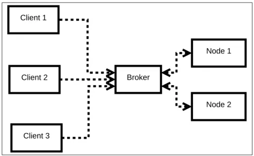
3.9 Example usage of Broker pattern . . . 47
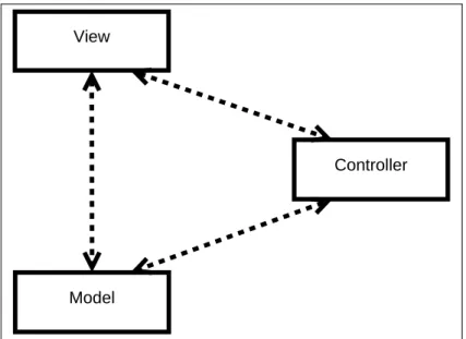
3.10 Example usage of MVC pattern . . . 48
3.11 Example usage of PAC pattern . . . 49
3.12 Example usage of Microkernel pattern . . . 49
3.13 Example usage of Reflection pattern . . . 50
3.14 Example usage of Interceptor pattern . . . 50
3.15 Example usage of Half–Sync Half–Async pattern . . . 51
3.16 Example usage of Shared Repository pattern . . . 52
3.17 Example usage of Messaging pattern . . . 53
3.18 Example usage of Client Server pattern . . . 53
3.19 Example usage of Explicit Invocation pattern . . . 54
3.20 Example usage of Peer–to–Peer pattern . . . 55
3.21 Example usage of C2 pattern . . . 56
3.22 Example usage of Active Repository pattern . . . 57
3.23 Example usage of Active Remote Procedure Call pattern . . . 57
3.24 Example usage of Implicit Invocation pattern . . . 58
4.1 Relationship between SOA elements . . . 80
4.3 SOA layers of abstraction according to IBM . . . 88
4.4 SOA target architecture . . . 97
5.1 Migration step 1 . . . 113 5.2 Migration step 2 . . . 114 5.3 Migration step 3 . . . 115 5.4 Migration step 4 . . . 115 5.5 Migration step 5 . . . 116 5.6 Migration step 6 . . . 117 5.7 Migration step 7 . . . 117 5.8 Migration step 8 . . . 118 5.9 Migration step 9 . . . 119 5.10 Migration step 10 . . . 119 5.11 Migration step 11 . . . 121 5.12 Migration step 12 . . . 122 5.13 Migration step 13 . . . 123
5.14 Overview of the criteria . . . 124
5.15 Wrong MVC architecture . . . 141
5.16 Architecture of TRWAM system . . . 142
5.17 TRWAM –all the use cases . . . 142
5.18 GUI of TRWAM . . . 143
5.19 Flow of implemented add assets process . . . 144
5.20 Composite Application –a deploy model of add asset process . . . 144
5.21 Architecture of migrated project . . . 145
3.1 Summary of architectural patterns investigation . . . 41 3.2 Architectural Patterns –View organisation. Adopted from [8] . . 61 3.3 Architectural Patterns –categories with their representatives . . . 65 3.4 Identified amount of patterns. Adopted from [38] . . . 67 3.5 Popularity of particular patterns. Adopted from [38] . . . 68 3.6 Popularity of pairs of architectural patterns. Adopted from [38] . 69 4.1 Summary of pattern types . . . 91 4.2 Examples of Rejected SOA patterns . . . 92 4.3 Selected SOA architectural patterns . . . 95
Abstract i
1 Introduction 1
1.1 Background . . . 1
1.2 Problem Statement . . . 4
1.3 Research Methodology . . . 6
1.4 Outline of the thesis . . . 8
2 Related Work 10 2.1 Migration toward SOA –“colour techniques” . . . 11
2.1.1 White–box: Service–Oriented Migration and Reuse Tech-nique . . . 11
2.1.2 Advantages and drawbacks of SMART . . . 16
2.1.3 Black–Box: Wrapping . . . 17
2.1.4 Gray–Box: Taxonomy analysis . . . 21
2.1.5 Advantages and drawback of Taxonomy Analysis . . . 23
2.2 Other approaches . . . 24 2.2.1 Architectural–Driven Modernisation . . . 24 2.2.2 PCBMER . . . 26 2.2.3 Peer–to–Peer . . . 28 2.3 Summary . . . 29 3 Architectural Patterns 30 3.1 Patterns . . . 33
3.1.1 Patterns in Software Engineering . . . 34
3.1.2 Definition of Architectural Patterns . . . 35
3.1.3 Sources of Architectural Patterns . . . 39
3.1.4 Identified Architectural Patterns . . . 40
3.2 Categorisation . . . 42
3.2.1 Description of selected Architectural Patterns . . . 43
3.2.2 Methods of patterns categorisation . . . 58
3.2.3 Allocation of patterns to categories . . . 61
3.2.4 Selection of representatives . . . 62
3.3 Mutual Interaction . . . 65 vi
3.3.3 Popularity of architectural patterns in real systems . . . . 67
3.3.4 Representatives of categories in real systems . . . 69
3.4 Pattern Selection . . . 70
3.4.1 Prefeasibility Study . . . 71
3.4.2 Pattern for migration . . . 72
3.5 Summary . . . 73
4 Service Oriented Architecture 74 4.1 Definition of Service Oriented Architecture . . . 75
4.2 Elements of SOA . . . 76
4.2.1 Main elements . . . 76
4.2.2 Other elements . . . 77
4.2.3 Types of services . . . 77
4.2.4 Structure of a service . . . 79
4.3 SOA –business point of view . . . 80
4.3.1 Properties of Services . . . 80
4.3.2 Activities . . . 82
4.4 SOA –architectural point of view . . . 84
4.4.1 Fundamental SOA . . . 84
4.4.2 Networked SOA . . . 84
4.4.3 Process–Enabled SOA . . . 85
4.5 SOA Vendors . . . 86
4.5.1 IBM –Layers of abstraction . . . 86
4.5.2 IBM –SOA Foundation Suite . . . 87
4.6 Architectural Patterns in SOA . . . 89
4.6.1 SOA patterns . . . 90
4.6.2 SOA–The target architecture . . . 96
4.7 Benefits of SOA . . . 96 4.8 SOA Manifesto . . . 100 4.9 Summary . . . 101 5 Guidelines 102 5.1 Pattern Languages . . . 103 5.1.1 MVC Pattern Language . . . 103
5.1.2 SOA Pattern Language . . . 104
5.2 Guidelines . . . 112
5.2.1 Description of Guidelines . . . 113
5.3 Project for migration . . . 122
5.3.1 Selection Criteria . . . 123
5.3.2 Source of projects . . . 124
5.3.3 Application of the criteria . . . 125
5.4 Application of the guidelines . . . 129
5.4.1 Results . . . 135
5.5 Discussion . . . 138
5.5.1 Processes . . . 138
5.5.2 Structure . . . 139
5.5.3 Advantages and Drawbacks . . . 140
6 Conclusion 146 6.1 Conclusion . . . 146
6.2 Answers to Research Questions . . . 146
6.3 Future works . . . 150
6.4 Summary . . . 150
References 151
Introduction
1.1
Background
With each passing year, more and more systems become obsolete. New technolo-gies are invented. The old systems become useless not only because of technical challenges, but also maintenance becomes more and more costly and complicated. Those issues may force companies to change their old system. This change can be achieved in two ways. The first way is to replace the existing system with a new one. However, the approach seems to be accurate, there is one very important issue in the way: cost. Replacing the old system is very costly in terms of money and time, which is required to create a new system almost from the scratch [51]. Migration of large projects is a serious and risky task that requires careful analy-sis of feasibility and required efforts [48]. An example of seriousness of migration is provided by Scott Bolling [17]. He participated in migration of a system. The migration had 25 unsuccessful migration attempts. The second approach is to migrate from old systems to new systems that use the newest software develop-ment paradigms and follow the recent technologies.
Available literature related to migration of legacy systems shows that legacy systems migrate not only toward specific applications like Multi-tier Applica-tions [27] or Client Server ApplicaApplica-tions [63]. The systems migrate also to meet approaches in software development like Object Based Environment [72] [51], Product Line [18] or Service Oriented Architecture [75][48].
Migration to Object Based Environment can be performed with help of wrap-ping technology. Application of the technology results in creation of wrappers. A wrapper is a new code that encapsulates the legacy code. The wrappers are called ”Legacy objects”. Those objects provide interfaces that enable usage of wrapped code. Application of this approach supports reimplementation of selected Legacy Objects independently. The legacy objects remain unchanged until a new and equivalent implementation is ready [51]. Wrapping technology distributes migra-tion effort over time.
Migration to Product Line is not as popular as migration toward Object Based Environment. Product Line is meant to increase large-scale software reuse and reduce time to market. Application of Product Line supports well market driven development [18].
Migration trend aims also at migration toward Service Oriented Architecture (SOA). SOA is an approach to software development[13] that integrated business processes and IT infrastructure. Architecture of a system designed in SOA-way is a package of loosely coupled interoperable services that exchange data and ex-pose their functionalities via interfaces. A service is “an asset that corresponds to real-world business activities or recognizable business functions”[59].The con-cept of SOA changed during the years and evolved from concon-cepts like distributed computing and modular programming [68]. Successful migrations toward SOA have been achieved in many domains including banking, electronic payment ap-plications and development tools [48]. In spite of all those successful migrations, a person that decided to migrate toward SOA has to be aware that migration toward SOA is not an ultimate solution to all problems with old systems. Migra-tion to SOA needs an addiMigra-tional time that is needed to understand this concept. Misunderstanding raises misconceptions [47]that may be costly. Choice of SOA relates to both technical and design challenges, because not every system can be presented as a set of reusable services or the cost of such adaptation disqualifies SOA as a solution[47].
Literature presents several examples of techniques of migration toward SOA, but three of them are especially important. They present different types of mi-gration to SOA and they are well described. The first is Taxonomy Analysis that analyzes the existing code [84].The next technique suggests to treat legacy sys-tem as a ”black box” and to wrap its code into services [77]. The last approach is rather a family of five approaches. It is called Service Migration and Reuse Technique (SMART) [10].
Taxonomy Analysis is a method that uses an existing code and documenta-tion as an input. Analysis of the documentadocumenta-tion set boundaries of the system and identifies services [84]. The services are described on business level. Analysis of the available code provides a dendogram [84]. This diagram in form of a tree presents the most often-used terms and relations between them. This approach is semi automatic because a decision person (like an architect) has to set cutting points that divide the tree into subtrees. Those subtrees are further implemented as services.
Wrapping as a technique of migration to SOA is similar to migration toward Object Based Environment. The migrated system is wrapped into a set of ser-vices that cover all the use cases covered by the actual system. The wrapping
technique conducts a three steps migration [23] The first step is meant to identify use cases and candidate services that cover those use cases. The description of this step does not provide own way of identification of services, instead it refers to works of Sneed [76] or SMART [49][10].The identified services are wrapped into services during the second step. The last step is deployment and validation. This step establishes infrastructure and deploys already created services. The services are further tested in order to assure that the migrated system fulfills requirements. SMART is a family of five approaches of migration toward SOA [10]. The basic SMART approach is SMART-Migration Pilot (SMART-MP). SMART-MP iden-tifies services and their components. This technique estimates potential risks and tries to provide a migration pilot with strategies for migration of the whole sys-tems. Four remaining approaches are tailored version of the basic case. SMART Service Migration Feasibility (SMART-SMF) focuses mainly on feasibility of mi-gration and its risks. SMART Enterprise Service Portfolio (SMART-ESP) dedi-cated for companies that decided to migrate their system but they did not identify all the services. SMART Environment (SMART-ENV) is meant for companies that did not select the target platform for migrated system. This approach aims at selection of this platform with analysis of its implications like risks and cost. The last family member is SMART System. This technique supports migration from initial estimations and analysis, through implementation and selection of environment till the end of migration. The SMART family provides guidelines for migration, but the guidelines are not complete [3]. They neglect impact of architecture of migrated systems on the process of migration and the target ar-chitecture.
Descriptions of those three approaches allows identifying following advantages and drawbacks:
Taxonomy analysis
Advantages
1. Identifies relations between services 2. The technique is systematic
3. Execution of the technique can be performed semi automatic 4. Provides a lot of information about the migrated system Drawbacks
1. The technique does not consider architectural patterns that are applied in architecture of migrated systems
2. Requires documentation - this causes problems because documentation of an old system may be missing or not maintained
Wrapping
Advantages
1. The technique is systematic
2. Execution of the technique is semi automatic Drawbacks
1. The technique does not consider architectural patterns that are applied in architecture of migrated systems
2. A full list of use cases is needed. The use cases are described in documen-tation that may be missing or not maintained
3. The technique bases on inputs and outputs of the system. It is hard to define all possible combinations of input-output pairs.
SMART
Advantages
1. The technique is systematic
2. The technique produces many artifacts that help in understanding the mi-grated system
3. SMART has a few variants that are tailored to different needs Drawbacks
1. The technique does not consider architectural patterns that are applied in architecture of migrated systems
2. Application of the technique requires a lot of time
1.2
Problem Statement
Identified techniques of migration to SOA do not consider architectural patterns applied in the migrated system (see first drawback of each technique ).
Usage of architectural patterns during migration is important because they express some common structure of the system. A migration technique that bases on an architectural pattern could provide a structured and systematic way of migration for systems characterised by this particular pattern. Additionally, it
was noticed that identification of design pattern helps in identification of services [7].
Aim
This thesis is meant to elaborate guidelines that support migration from a system that is based on a chosen architectural pattern toward a system based on Service Oriented Architecture.
Objectives
The objectives of the thesis are as follows:
1. To investigate existing migration toward SOA approaches.
2. To investigate existing architectural patterns in order to select the pattern for migration.
3. To investigate SOA in order to provide understanding of SOA in the context of this work.
4. To elaborate the target architecture.
5. To elaborate translation between selected architectural pattern and the tar-get architecture
6. Illustrate an application of the translation.
Research question:
To fulfill the aim and the objectives, the thesis addresses and answers following research questions:
RQ.1 What are the existing techniques of migration toward SOA?
RQ.2 What are drawbacks and advantages of identified techniques of mi-gration toward SOA?
RQ.3 What process employ in order to select the pattern for migration?
RQ.4 Which pattern should be chosen for migration?
RQ.5 What elements should be the building blocks of the target architec-ture?
RQ.6 How the target architecture should look like?
RQ.7 How to translate the selected architectural pattern into the target architecture?
RQ.8 What are the drawback and advantages of the new technique ?
Expected outcomes: The following outcomes are expected to be elaborate by the thesis.
EQ.1 List of techniques of migration toward SOA with descriptions
EQ.2 List of drawback and advantages of found techniques of migration toward SOA
EQ.3 Process for selection of the migrated architectural pattern, motivation behind the activities
EQ.4 Architectural pattern for the migration
EQ.5 List of elements building the target architecture
EQ.6 Target architecture
EQ.7 Guidelines for migration
EQ.8 Example illustration of implementation of the migration according to the guidelines
EQ.9 Advantages and drawback of the guidelines for migration to SOA
1.3
Research Methodology
This study is conducted in two domains: Architectural Patterns and Service Ori-ented Architecture. Both of the domains are covered by a number of publications. Entry points for the research are books containing body of knowledge. The books were identified during elaborating the topic for this thesis. For Architectural Pat-terns, the series of books by Frank Buschmann [22][71][45][20][21] is considered as a body of knowledge. In turn, body of knowledge for Service Oriented Ar-chitecture or more precisely Architectural Patterns in SOA is described in“SOA Design Patterns”[32] by T.Erl. In case of migration to SOA, the entry point are techniques for migration to SOA described in introduction (see section 1.1). Those approaches and other further identified are deeper investigated in order to get better understanding what is done and how it is done.
The basic research methods applied in this thesis are Literature Review, Anal-ysis and Synthesis. The core of the literature review applied in this thesis are books containing bodies of knowledge and publications describing identified tech-niques for migration. Those sources are investigated in the first order. If they
do not provide satisfying information then other books, conference and journal papers are studied. Web pages are referenced mainly when some knowledge about technology is needed. Literature review is conducted until a satisfying informa-tion is not found. The review takes into account year of publicainforma-tion of found sources. The newest publications are revised in the first order. The main sources of journals and conference papers are: IEEE, Inspec, Springer and ACM digital library. Literature review in domain of Architectural Patterns and SOA is con-ducted separately. Information provided by literature review is further analysed and synthesised
Literature Review in the domain of Architectural Patterns is applied in order to establish procedure for selection of architectural pattern( answer for RQ.3).The procedure is further applied and results of each activity is analysed. The pattern for migration is chosen based on those results (answer for RQ.4).
In case of SOA, literature review is conducted twice. The purpose of the first review is to investigate the existing methods of migration to SOA (answer for RQ.1). The second literature review is meant to find elements that will build the target architecture (answer for RQ.5). The identified methods of migration are further analysed in order to identify their advantages and drawbacks (answer for RQ.2). Design of the target architecture (answer for RQ.6) is result of analysis outcome of literature review providing building blocks of the target architecture. Information gathered during selection of the architectural pattern for migration and elaboration of the target architecture is further synthesised in order to elab-orate translation between the chosen architectural pattern and the target SOA (answer for RQ.7). Finally the information gather during analysis of identified migration to SOA techniques is synthesised with the elaborated guidelines (an-swer for RQ.8).
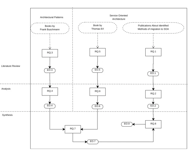
Overview of the described process is presented in figure 1.1. The EO.8 is not present in the figure because it is not a direct outcome of research questions.
Literature Review
Analysis
Synthesis
Architectural Patterns Service Oriented
Architecture RQ.1 RQ.2 RQ.3 RQ.4 RQ.5 RQ.7 RQ.8 RQ.6 EO.1 EO.3 EO.2 EO.4 EO.5 EO.6 EO.7 EO.9 Books by Frank Buschmann Book by Thomas Erl
Publications About Identified Methods of migration to SOA
Figure 1.1: Relation between research questions, outcomes, methodologies and do-mains of interest
1.4
Outline of the thesis
The thesis is organised as follows:Chapter 1 presents background information about the problem of migration of a legacy system along with researches, objectives to achieve and problem state-ment.
Chapter 2 presents related works.
Chapter 3 presents selection of a pattern for migration with procedure and results
Chapter 4 describes background information about SOA and presents the tar-get architecture with its justification.
Chapter 5 presents guidelines for migration with their motivation. Addition-ally an example application of the guidelines is presented.
Chapter 6 summarised the work, provides future works and answers research questions.
Related Work
Motivation behind migration is a result of two factors. The first factor is the fact that old but very often mission critical systems cannot be developed or maintained anymore because it becomes too expensive. This factor is called [74]“Legacy Sys-tem dilema”. The second factor describes why a company does not want to develop a new application from the scratch. This may include for instance lack of documentation of the system. Additionally, the system can be a mature appli-cation that is a result of many years of development and maintenance. When a company decides to migrate an application, it always has to face two very general problems [74]. The first problem is caused by own, old application which was developed for years and may be lacking in documentation. The second problem is a target system, namely the architecture and migration decision that are asso-ciated with selection of the target system.
One of possible migration directions is migration toward Service Oriented Ar-chitecture which brings some very promising benefits like code reuse and easy further integration (see 4.7).But even if the choice is made, still an open ques-tion remains: How to conduct the migration? According to Z.Zhang and H.Yang there are three types of migration toward SOA [84].The first approach called White–Box requires high understanding of the system and allows to make sig-nificant changes in code if there is such need. The second approach is focused rather on input and output of the system and is called Black–Box. The third approach lies between white and Black–Box techniques and it is called Grey–Box technique. The ”Gray–Box” technique includes code analysis, modification of the code and analysis of behaviour of the system as a whole entity.
How does migration is important is also evidenced by the fact that it be-came a subject of standardisation. The standard, named Architectural–Driven Modernisation (ADM) is meant to facilitate migration efforts[58]. This standard considers system on three levels of abstraction. The standard investigates also role of patterns in the system. Migration towards Service Oriented Architecture became also a subject of interest of architects dealing with non–SOA architectural patterns like patterns identified in the second chapter.
This chapter is meant to investigate techniques of migration toward SOA in order to set context of the work and identify advantage and drawback of the exist-ing methods. The study aims at mature and well described migration techniques but techniques that base on architectural patterns are also briefly presented. The chapter is organised as follows:
1. Migration toward SOA – “colour” techniques
This section presents three example techniques that correspond to White–Box, Black–Box and Grey–Box approaches. Descriptions provided by available literature give an overview of studies conducted in the field of migrations toward SOA. Additonally, the section presented advantages and drawback of the presented techniques.
2. Other approaches
The section presents three other approaches. The first approach is not dedicated for migration toward SOA, but the steps taken during migra-tion reflect steps taken during creamigra-tion of SOA. The remaining two tech-niques present different approaches of migration of an architectural pattern to SOA.
3. Summary
The summary presents result of investigation in the field of migration toward SOA.
2.1
Migration toward SOA – “colour techniques”
This section presents briefly examples of migration techniques described byZ.Zhang and H.Yang[84].2.1.1
White–box: Service–Oriented Migration and Reuse
Technique
Service–Oriented Migration and Reuse Technique (SMART) is rather a family of processes then a single process. It is meant to support organisations in making initial decision about feasibility of migration system towards SOA [10]. SMART evolved from the Options Analysis for Reengineering (OAR) method developed at the SEI. [49][10]
Family members
However SMART family consists of five members, the members are just tailored variants of the first technique–SMART–Migration Pilot (SMART–MP), therefore this ”root” approach in opposite to remaining family members is described more detailed.
SMART–MP – SMART Migration Pilot focuses mainly on early project anal-ysis. The analysis determinates potential challenges, trade–offs, risks and cost by identifying potential services and their components [10]. Migration Planning tries also to recognise pilot project and appropriate migration strategies [10]. Ac-cording to SMART–MP description[10], the technique consists of four following elements :
1. Element 1 –SMART–MP Process
The first element is a process that is meant to analyze the gap between both the actual and a target system by gathering information about legacy components and potential services build on them. Gap analysis leads to development of an initial migration strategy.
2. Element 2 –Service Migration Interview Guide (SMIG)
Interview Guide aims at identification of potential risk and costs associ-ated with the migration process. The identification is based on answering questions, which are categorized in more than 60 categories [10].
3. Element 3 –SMART Tool
The tool supports data collection and organization. The support of assig-nation of answers to the question to related risks [10].The tool uses SMIG as a framework to create a draft migration strategy.
4. Element 4 –Artifact Templates
The element consists of templates for following artifacts [10]: Migration Issues List, Business Process–Service Mapping, Service Table, Component Table, Service – Component Alternatives Table and Migration Strategy. Elements presented above are further used during migration process by SMART activities (see figure 2.1). SMART–MP technique distinguishes six iterative pro-cesses:
1. Process 1 –Establish Context
Establishing of the context is the first SMART–MP process. The process is meant to gather basic information about the system by describing its business and technical context. Business context includes identification of stakeholders and identification of their goals. The technical context includes identification of candidate services and analysis of legacy system. Services identified during this step are generic because generalisation helps to deter-minate project feasibility and provides required experience if the decision about migration is made [10]. However, this is the first SMART process, it generates three out of eight documents [10].
(a) Stakeholder List –contains list of stakeholders with contact data and information to elicit from each of them.
(b) Characteristic List –contains a set of predefined characteristics meant to support decision about migration feasibility. The information refers to legacy system’s components.
(c) Migration Issues List –the list contains information about potential migration issues of both the system and single components
2. Process 2 –Define Candidate Services
Service Candidate Definition is restricted to a small number (typically 3–4) of well defined in the previous step services. A good candidate keeps high cohesion, high reuse (see 4.3.1) and clearly defined input and output. Fi-nally, selected services are specified more precisely in terms of Quality of Service (QoS) and definition of input–output.
3. Process 3 –Describe Existing Capability
Capability description is meant to localize and gather information about components of legacy system that contain functionality required by previ-ously selected services [10]. The description of component includes both architectural view like design paradigms, system quality and technical view like implementation platform, language, code documentation, code size [10], age of the components, code complexity and interfaces for users and systems [49].Asides from gathering technical and business description, components should be described from quality point of view, by taking into consideration their change history, outstanding problems, likehood of meeting long term needs and historical cost of development and maintenance [49]. All this information is presented in two formal artifacts:
(a) Component Table – contains only components meant for migration to services. The table captures also characteristics described in charac-teristic list.
(b) Service Table –contains a list of possible services derived from compo-nent table with characteristics of those services.
4. Process 4 – describes Target SOA Environment
Description of a target environment includes major components of target environment with influencing technologies and standards, guidelines for vice implementation, their interaction with environment and quality of ser-vices (QoS) [10].
5. Process 5 –Analyse the Gap
The gap analysis is meant to provide preliminary approximation of costs and risks of particular services allocated from the legacy system. The ap-proximation is based on necessary changes of each required component. In turn, the allocation is based on characteristic of SOA environment and re-quirements coming from previously identified services. Gap analysis has
two main goals. The first is to identify gaps in knowledge about the legacy system. The second is to create Component Option Table which is used as an input to the final process.
(a) Component Option Table –maps possibilities between Service Table and Component Table. The table contains also mapping used in sys-tem Commercial Off The Shelf (COTS) components. There are two possible ways in which the process can be conducted [49]. The first is “manual” allocation of components prepared by SMART team.The second approach is enriched by supporting tools. The supporting tools are used mainly for analysis of the code that does not have complete documentation or quality of the code is not determined.
6. Process 6 –Develop Strategy
Strategy development is the last and the final SMART–MP process. The process makes use of all the previously gathered information including mi-gration issues and information related to cost and risk estimations. Both cost and risk estimations have to be determined precisely, because they set additional constrains for the project. They also decide about feasibility of the project. In turn, migration issues include [10]identification of a pilot project by identification of initial set of services and the order of their im-plementation. The issues address guidelines created during describing of the target environment and specify possible migration paths like wrapping or re–writing [49]. In result, two artifacts are created:
(a) Migration alternatives table – alternative table takes as an input Com-ponents Service Options Table and produces feasible migration strate-gies. The strategies differ mainly in a list of components selected for migration, order of processes and code modification.
(b) Service Migration Strategy – migration strategy is a final document that is a result of all the processes and artifacts. The strategy de-scribes services that can be implemented and what components would create them. The document contains also description of the processes required to accomplish the migration and full cost and risk analysis.
Figure 2.1: SMART work flow. Adopted from [10]
However the numeration assigned to each process may suggest that the pro-cesses are strictly sequential, it is not true. Moreover the propro-cesses should be conducted in an iterative manner and the order of activities can be changed to align to changes better and better support project specification [50]. Con-sequently, iterative approach forces to reconsider previous steps if information gathered in current steps influences it. Reconsideration refers also to artifacts obtained as results of the processes. SMART–MP contains one more element which has significant impact on the Process of migration but was not mentioned before. This element is a decision point that is localized after Establishing Con-text. The decision point provides initial answer for the question: “Is the project feasible to create?”.The answer for this question is based on artifacts acquired from the first step and relays on availability of stakeholders and a level of both
current and target system understanding.
SMART – SMF Application of SMART Service Migration Feasibility deter-minates wherever the project is feasibly for migration toward SOA. This version of SMART is meant for companies that are new in the field of Service Orientation or migration of projects that are characterized by a high risk of migration.
SMART – ESP In opposite to SMF, Enterprise Service Portfolio (ESP) is designed for enterprises that decided to migrate their systems to SOA. ESP sup-ports creation of service portfolio. The portfolio is based on services selected from all the systems across the organization.
SMART ENV The Environment variant is something between ESP and SMF versions. This variant is the best for organization that chosen SOA as their target environment but they are still not completely aware of implications, costs and risks of migration.
SMART System SMART System is designed from a perspective of migration of a current system to a complete Service Oriented environment. SMART Sys-tem supports identification and creation of services. This variant establishes a complete Service Oriented infrastructure[10].
2.1.2
Advantages and drawbacks of SMART
The SMART migration technique is a technique that examines the migrated sys-tem in details. This high level of granularity of the examination brings both advantages and drawbacks.
Advantages
1. The technique is systematic
2. SMART examines the migrated application from different points of view, including risks, costs and migration feasibility
3. The technique produces many artifacts that help in understanding the mi-grated system
Drawbacks
1. Application of the technique requires a lot of time 2. The technique is heavy. It produces a lot of documents
3. The technique does not consider properties of architecture of migrated sys-tem
2.1.3
Black–Box: Wrapping
In opposite to White–Box technique, Black–Box technique does not affect the code of the migrated system. The system is considered as a whole entity and analysis of a legacy system is limited only to analysis of inputs and outputs. This section presents briefly an overview of an example of a Black–Box technique, namely Wrapping [23].The description presents two parts of the approach. The first part describes basic elements. The second presents main processes
Elements
Wrapping technique consists of several element that work on Finite State Au-tomation and legacy screens. See picture 2.2 for wrapper schema. The elements are following:
Terminal emulator – replaces server terminal that normally has an access to the legacy system and transfers requests from a GUI based application or requests called via legacy system’s API. In other words, terminal emulator provides an interface to access legacy functionality. The implementation depends of terminal type. There are two main types of terminals [23]:
1. Stream Oriented Terminal –communicates with the system via two–directional channel. The terminal sends data just after they are typed. Received data are computed by the legacy system and send back as a screen represented by a matrix of characters.
2. Block Oriented Terminal –in opposite to stream terminal, Block Oriented Terminal uses screens represented by a set of fields with their localisation. The legacy system computes the result and sends back a screen containing a new set of fields with corresponding localisations.
States identifier – Given an input and a start state, the system can reach a finite amount of states. Each state has own screen that is returned by the system as an output. The responsibility of State Identifier is to match Screen Template to the screen returned by the system. To increase matching probability, the legacy screen should be described by the biggest possible amount of data that can be obtained using reverse engineering on the legacy screen.
Repository – stores Finite State Automaton (FSA) files with corresponding Screen Templates, Automation Variables and actions executed by wrapper after reaching this particular state. These actions include [23]:
1. Init –sets Automation Variables based on Service Request Message 2. Set Input Field –sets a value of an input field
3. Get Output Field –gets a value of an output field from the legacy screen 4. Submit Command –triggers transition from one state to another
5. Set –Update Automation Variable –modifies values of Automation Vari-ables based on output of variVari-ables of legacy screen and other Automation Variables
6. Build Response –creates a service response based on actual values of Au-tomation Variables
Automation Engine – Automation Engine is a core of the approach. The engine is a component that receives web service request and returns an output. Execution of Engine functionality starts once components receive URI of invoked functionality and corresponding input data. Component execution can be divided into three parts [23]:
1. Start Activity –starts when the engine receives request message. Just after the start a corresponding XML description file is acquired from the Repos-itory and the legacy system is invoked. The first screen returned by the legacy system is obtained from Terminal and a current state is obtained from State Identifier.
2. Interpretation Activity –Interpretation Activities are a set of activities re-peated in a loop until the final state is not reached. The set includes execu-tion of current state activities, update of variable buffer called Automaton Variables, transfer of a new data to Terminal Emulator and identification of a new state.
3. Final Activity –when the last state has been reached, engine create an output message based on Automation Variables values.
Processes
In order to achieve fully migrated system, three steps should be executed in a sequence. The steps are following:
Figure 2.2: Wrapper Schema. Adopted from [23]
Selecting candidate services – This is the first process of the wrapping tech-nique. The process is meant to identify and allocate potential services in legacy system. However the approach notices meaning of introduction of a structural process in order to support service allocation, it does not provide own solution, but rather refers to work of Sneed [76] or SMART [49][10]
Wrapping the selected use case – The second process is a core part of the technique. This process aims at wrapping identified use cases into service. It is also the most complex process which is composed of three sub–processes [23]:
1. Service Identification –aims at selection of use cases that can be transformed to services with respect to previously described characteristic (see 4.3.1)and braking down complex use cases into more elementary [23]. Complex ser-vices are not removed from the list serser-vices. They became process serser-vices that utilise lower level services to perform tasks.
2. Reverse Engineering –during the second sub–activity, the system is analysed in terms of interaction with user in order to gain broad and in depth coverage of main and alternative scenarios. As the result, information about request
/ response messages and corresponding screens are gathered and following outputs are generated [23]:
(a) Finite State Automation – contains all identified states, transitions between the states and transition triggers. The automation is not de-terministic because given the same input; user may have a few available paths to follow.
(b) Screen Templates – contain sets of screens that correspond to each state from FSA. Each screen contains features like labels and their localisation. This information is necessary for automatic identification. (c) Interface –more precisely service contract with all the input and output
variables (see 4.2.4).
3. Wrapper Design – the last process makes use of previously created Inter-action Model. Designing is meant to make a model interpretable by Au-tomation Engine. In order to achieve interpretability, the model has to be enhanced by an additional information regarding activities executed by Engine on Automation Variables or screen fields. The additional data may contain localization of a field, commands, input /output fields etc.
Deploying and validating the wrapped use case The last process is noth-ing more than establishnoth-ing infrastructure for services and testnoth-ing whether they fulfill requirements [23].
1. Deployment –includes all the information required to export and publish services. The process is dependent on selected technology, for instance: selection of Web Service requires creation of WSDL document [23]
2. Validation –since a significant part of the second process uses automation for creation of Finite State Automation, validation gains in value and becomes a mandatory activity. The Validation aims at identification of failures. The failures may manifest as a lack of screen or an a received message is different than expected. Validation process can be performed in following manner [23]:
(a) Regressive testing – tests take as an input data used during Reverse En-gineering and check whether expected output is delivered by a legacy system. The tests require coverage on scenario level, what means that every scenario of each use case have to be executed at least once [23]. (b) Path testing – the second approach requires analysis of FSA in order to design tests covering each independent path. This means that all nodes and edges of the FSA need to be visited at least once. Path Coverage is a high level testing that requires a lot of effort to identify all possible paths.
Advantages and drawbacks of Wrapping
Wrapping is a technique that does not examine code of the migrated application. In turn, this approach requires a documentation that is up to date. The migrated system also must be developed as a set of separated artifacts.
Advantages
1. The technique is systematic
2. Execution of the technique is semi automatic
3. There is no need to have code of the migrated application
Drawbacks
1. Documentation of the migrated system is a must. The documentation must be up to date.
2. A full list of use cases is needed. The use cases are described in documen-tation that may be missing or not maintained
3. The technique bases on inputs and outputs of the system. It is hard to define all possible combinations of input-output pairs.
4. The technique does not consider properties of architecture of migrated sys-tem
5. Wrapping requires very complex and time consuming testing at the end of migration.
6. The application must be developed as a set of components that can be separately wrapped.
2.1.4
Gray– Box: Taxonomy analysis
Gray–Box is a compromise between white and Black–Box techniques. It takes analysis the migrated system on both code and system level. The approach presented in this section derives from clustering analysis. The clustering analysis is applied in order to allocate fully functionally and reusable services. Clustering analysis is a sequence of following processes 2.1.4:
Service Identification –Service Identification underlines all the processes as-sociated with migration toward Service Oriented Architecture. In context of the presented approach, the identification is based on analysis of documentation, es-pecially requirement documentation. The identification consists of two steps [84]: 1. Sub domain identification –includes analysis of selected sub–domains in
order to define boundaries of the whole legacy system.
2. Further analysis –carries the burden from strict analysis to modelling, espe-cially on modelling of the whole system as UML diagram that is afterwards transferred to third party software. The diagrams are expressed in XML [84]. The model serves as an input for identification of potentially reusable components that latterly may be provided as services. Those services are calledlogical services and they are spanned between concept of service itself and the technical realisation separated from legacy code.
Legacy System Understanding –The second process is intended to esti-mate potential migration chances and model the system. According to Zhuopeng Zhang[84],a system is suitable to migrate toward SOA when the system contains reusable business functionality that in comparison to the whole system is rea-sonably maintainable. Moreover, the functionality should bring additional value after exposing it as a service. Having estimation done, a model of the system should be elaborated. Elaboration of the model is based on a re–engineering process and analysis of existing documentation including technical documenta-tion, graphs, interfaces and other existing models. Approach description includes different treatment of procedural software and object–oriented (OO) software. Re–engineering of procedural–application in opposite to OO applications involves usage of additional tools in order to obtain candidate classes and intermediate object–oriented model. In turn, Intermediate Model incorporates UML repre-sentation, event driving programming models and object oriented programming language [84]. Object–Oriented approach tries to define system on different levels of abstraction by creation of UML class diagram and control flow graph.
Agglomerative Clustering Analysis – Agglomerative Clustering requires a set of data for reorganization purpose. This set of data in case of migra-tion involves funcmigra-tions, procedures and classes that are further clustered ac-cording to feature similarity. The similarity is a key concept in legacy system restructuring[84]. The technique defines features that are used to measure the similarity and determinate whether two entities belong to the same cluster. A feature reflects found identifiers–name. A name can identify any non local entity or a property of the entity including property, name or method name [84].
Then, the algorithm is executed (see [84] for more information about the algorithm).The algorithm produces a dendrogram that describes dependencies
between all the provided data. In order to allocate services, architects have to set cutting points manually and divide the diagram into sub–trees. The sub–tree become services. During service selection, architects have to take into consider-ation other informconsider-ation retrieved during previous steps as well as the amount of dependencies in order to receive coarse grained and loosely coupled services (see 4.3.1).
Service Packaging and Integration This is the last step of presented Gray–Box technique. The step accomplishes the process of migration from legacy system to-wards Service–Oriented Architecture. The last step is composed from a sequence of three sub–steps [84]:
1. Refinement –the services obtained as a result of all the previous steps are loosely coupled, but they still contain some dependencies. Refinement in-creases independence of those services and improve their quality by removal of all the“dead” code and unrelated interactions of interfaces. During this process also an interface for service communication is established [84]. 2. Component integration and packaging –component integration takes
previ-ously refined services and connects them with a “glue code” that serves as an adapter in order to transform ingoing and outgoing invocation. Addi-tionally, some differences between domain and retrieved model may appear. The differences should be filled up with new services.
3. Interface design –this step is meant to create interfaces[84],but in fact the output is a contract that specifies exact input and output for each operation of the service. Also an interface –a representation of the contract–is created. Application of clustering seems to be very promising solution because it base on very basic human activity–classification [4]. Generally, clustering is meant to re-organize groups of entities by taking into consideration their similarity and based on that divide them into more homogenous groups[4]. The similarity can vary as a domain of analysis and can be understood as for instance similarity of proper-ties which is measured with metrics. Method applied in this approach bases on an improved agglomerative hierarchical clustering [4],This technique emphasizes functional aspects [4]that are essential in SOA. The technique is presented as a set of processes and an algorithm.
2.1.5
Advantages and drawback of Taxonomy Analysis
Taxonomy Analysis analyses code of the migrated application in order to identify services and relationships between them.
Advantages
1. Identifies relations between services 2. The technique is systematic
3. Execution of the technique can be performed semi automatic 4. Provides a lot of information about the migrated system
Drawbacks
1. The technique does not consider properties of architecture of migrated sys-tem
2. Requires documentation - the documentation of an old system may be miss-ing or not maintained
2.2
Other approaches
The approaches described in the previous section present complex and generic techniques meant to migrate a legacy system to SOA. Their description did not go into details because the techniques need complex tailoring for each particular migration. The next group of techniques migrates systems toward SOA empha-sising architecture of the migrated system. This section presents three different approaches utilising benefits brought by architectural patterns. The first ap-proach is a try of standardisation of migration. In fact, the apap-proach does not refer only to migration but also to other activities changing the application. The fact that this is a try of standardisation makes this technique worth to describe. The next example presents modification of architectural pattern (PCBMER) in order to adjust it to SOA. The last approach presents how to create SOA based on Peer–to–Peer architectural pattern
2.2.1
Architectural–Driven Modernisation
Architectural Driven Modernisation is [58] “the process of understanding and evolving existing software assets for the purpose of software improvement; mod-ifications; interoperability; re–factoring; restructuring; reuse; porting; migration; translation into another language; and enterprise application integration.” The process describes modernisation of an architecture on three levels of abstraction [79]:
1. Technical Architecture Modernisation –includes migration between both platform and language or just platform or language. The migration may be caused by technology obsolesce, lack of further modernisation and mainte-nance possibilities or other technological factors.
2. Application and Data Architecture Modernisation –is modernisation on a higher level of abstraction that includes changes to architecture of the sys-tem and may require changes in structure of the stored data. The sation includes also Technical Architecture Modernisation. The moderni-sation may be needed, because the application due to incremental changes may become monolithic and impossible to maintain block of code.
3. Business Architecture Modernisation –is the most complex and the most risky type of modernisation. The risk is strengthening by lack of any stan-dardisation in the domain of migration of legacy assets. The complexity is a result of the scope of the modernisation process. The result includes both previously described modernisations.
Analysis of the modernisation processes within the context of Service Oriented Architecture allows making an assumption that the final version of the standard will align to migration towards SOA due to mapping between SOA structure and modernisation scope. While modernisation on a technology level corresponds introduction of SOA infrastructure into the application, modernisation on appli-cation and data architecture matches changes required during identifiappli-cation and specification of services.
Substandards – However Architecture–Driven Modernisation is presented as one standard, in fact it is a set of sub–standards that include different aspects of modernisation. There are following standards [64]:
1. ADM: Knowledge Discovery Meta–Model (KDM) –establishes an initial meta–model that describes the structure of the system and data model, but does not describe the system below procedural level.
Status ow work: Adopted in 2006
2. ADM: Abstract Syntax Tree Meta–Model (ASTM) –starts where KDM fin-ishes, namely ASTM describes the system below procedural level what guar-antees a full representation of the system.
Status ow work: Rolled out in 2009
3. ADM: Pattern Recognition –tires to identify structural aspects of the system by recognising both pattern and anti–patterns in order to define require-ments and opportunities for refactoring and transformation of the system.
Status ow work: Work started in 2009
4. ADM: Structured Metrics Package (SMM) –uses KDM in order to derive a set of various metrics describing different attributes of the system. Metric coverage includes technical, functional and architectural aspects of the sys-tem.
5. ADM: Visualization –illustrates meta–data collected in KDM. The visuali-sation includes charts, graph, views, metrics and UML models.
Status ow work: No target date set
6. ADM: Refactoring –includes modernisation of an application by structuring, rationalising and modularising.
Status ow work: No target date set
7. ADM: Transformation –brides existing application with the target system by defining possible mapping and transformations. It is worth to underline that the standard will target at usage of Model–Driven Architecture (MDA) paradigm.
Status ow work: No target date set
Those specifications cover many different aspects of modernisation but in con-text of this research mainly Pattern Recognition is very interesting. The fact that Pattern Recognition is becoming a part of standard emphasises contribution of pattern during migration. The status of work is taken from [64]. The document is dated February 2009 but it still available on the web page.
2.2.2
PCBMER
Presentation–Controller–Bean–Mediator–Entity–Resources (PCBMER) is an ar-chitectural pattern elaborated by Lech Maciaszek. The pattern is dedicated for highly adaptive systems [53]. The pattern is based upon Holistic theory. The theory says that a holon in a recursive entity that can contain other holons in-side. The theory is also enriched by Holarchy (Hierarchy of holons) [53]. The architecture consists of six following layers:
1. Presentation –is a top level layer and represents User Interface (UI). The interface provides information contained in beans from underlying Bean layer.
Depends on: Bean Layer, Controller Layer
2. Controller –corresponds to Controller from MVC or PAC architectural pat-tern. A controller encapsulates an enterprise business logic which is invoked by Presentation Layer
Depends on: Bean Layer, Entity Layer, Mediator Layer
3. Bean –represents information meant to be displayed on UI. A single bean is an object that consists of entities from Entity layer as well as additional properties.
4. Mediator –mediates between Resource Layer and Entity Layer. The pur-pose of the layer is to manage business transactions, enforce business rules, instantiate business objects in Entity Layer and manage the memory cache of the application.
Depends on: Resource Layer, Entity Layer
5. Entity –represents all the business objects within the application.
Depends on: Independent
6. Resources –mediates between application and data sources. The source can be a database, service or other external entity containing required informa-tion.
Depends on: External Resources
The pattern fits well to for business solution and as the business solutions become a subject of integration. The integration presented by L. Maciaszek aims at integration with Service Oriented Architecture. The pattern is modernised in order make the integration possible. The modernisation of the pattern is named PCBMER–U (Utility) and introduces three new elements into the pattern(see figure 2.3).
1. Broker –is a message broker
2. Orchestration –encapsulates and executes a new business logic (see 4.3.2 for more information)
3. Service Registry –is responsible for service discovering and depends only on mediator.
The modification seems to have some contradiction. The first is that according to description, Registry depends on “utility’s business logic in Mediator” [52] what in fact is quite interesting because Mediator Layer does not depend on Controller Layer, consequently Mediator layer is not ”aware” of Controller layer. Registry may not discover higher level services located in Controller. The next potential contradiction is where Orchestration is introduced. According to figure 3 in [52] Controller depends on Orchestration what seems to be against role of Orchestration, because in fact Orchestration / Process Services depend on underlying services what in this case may mean that Orchestration depends on services allocated in Controller layer. The last contradiction refers to the figure 3 and the description. Description says that Broker and Orchestration depend on logic in Controller Layer while the dependency in the picture is opposite. The same situation refers to Mediator Layer and Registry.
Figure 2.3: Relation between PCBMER and PCBMER–U, adopted (figure 3) from [52], potentially inconsistent dependencies are marked in red
2.2.3
Peer–to–Peer
Available literature provides also an example of mixture of both Service Ori-ented and non–SOA patterns. The approach proposes a union of services and Peer–to–Peer infrastructure. The infrastructure is build upon Gradient Topology and Distributed Hash Table. Gradient Topology supports efficient Peer discov-erability [29],Distributed Hash Table (DHD) provides efficient routing algorithm that enables consumption of services [69] and can be successfully employed as a mean of service discoverability and registration [50]. The infrastructure has also one more important element of the Peer–to–Peer pattern, namely a set of servers used as start up points for other peers (see 14 for more P2P related information). Gradient Topology supports also service registration through decentralized Ser-vice Registry [69].In order to register, a serSer-vice (peer) has to discover an instance of service registry via gradient topology. Then the service registers itself and up-loads own proxy via DHT. After this sequence of steps a service can be discovered by other services.
2.3
Summary
This chapter presents briefly main Service Oriented Migration approaches. The first three techniques are the most mature and have the more detailed documen-tation. SMART (White–Box) technique analyses the code in details. Wrapping (Black–Box) wraps the legacy system into services and does not integrate into code of the migrated legacy system. Taxonomy Analysis (Grey–Box) analysis the code of the migrated system. As the result of analysis a dendogram is created. The diagram is further converted into sub–threes that are implemented as ser-vices. Remaining three approaches differ in scope of migration. ADM migrates whole systems by migrating their infrastructure, architecture and business layer. In turn PCBMER is migrated to SOA using additional layers. The last technique applies architectural pattern on more abstract level. The whole communication within system is organised as a Peer–to–Peer network. Study of architectural patterns becomes a part of standard. Migration of the system will base upon white or black or grey technique.
Architectural Patterns
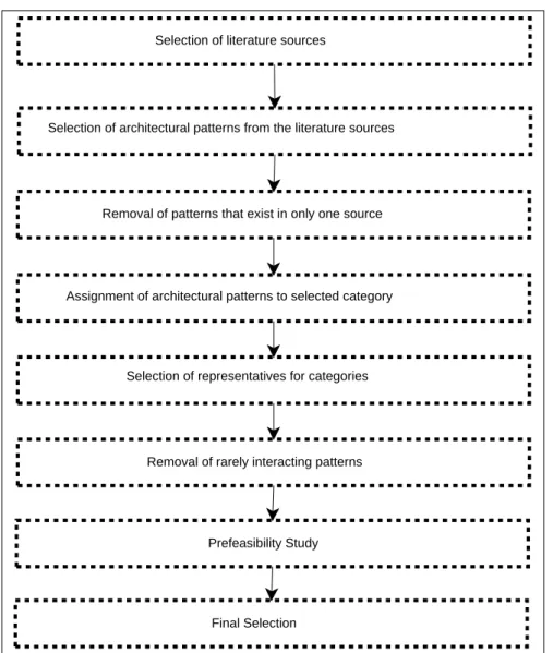
The goal of this chapter is to select an architectural pattern that will be migrated to Service Oriented Architecture (SOA). Selection of a proper pattern is very im-portant. The selection must eliminate patterns that are not feasible for migration, the patterns that are already migrated to SOA and the patterns that are already part of SOA. Additionally the selected pattern should be popular. It means that the pattern should be often implemented in real systems. Guidelines for a rarely used pattern have reduced application. Since there is a number of architectural patterns that differ from each other and the thesis is not meant to migrate all of them, a systematic approach for selection of the pattern for migration is needed. The selection bases on a number of steps. Each step is a filter that is meant to reduce number of candidate patterns or prepare the patterns for the next filter. Filters are lined so the output of one filter is the input for another. The filters (in order of their application) are following:
1. Selection of literature sources
The idea of architectural pattern along with example patterns is described in a great number of publications. This filter selects several literature sources that will be the base for identification of architectural patterns.
Input:Literature about architectural patterns
Output: Selected literature sources
2. Selection of architectural patterns from the literature sources
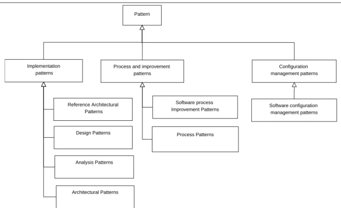
Literature sources selected by the first filter contain different types of pat-ters (see 3.1.1 for types of patterns), but only architectural patterns are in scope of the work. This filter removes all the non-architectural patterns.
Input: Selected literature sources
Output: List of architectural patterns
3. Removal of patterns that exist in only one source
This is the first filter that removes the less popular architectural patterns. All the patterns that exist in only one literature source are removed. This assures that the most unusual and rare patterns are not taken in the further consideration.
Input: List of architectural patterns
Output: Architectural patterns that exit in more than one literature source 4. Assignment of architectural patterns to selected category
In opposite to the previous filters, this filter does not reduce amount of architectural patterns. It organizes previously identified patterns. The out-put of this filter is a list of architectural patterns assigned to categories. Both identified and chosen categories are described.
Input: Architectural pattern that exits in more than one literature source
Output:Categories of architectural patterns and architectural patterns as-signed to those categories
5. Selection of representatives for categories
At this point, architectural patterns are grouped into several categories. Each category contains several patterns. This filter reduces number of can-didate architectural pattern by selection of patterns that represent partic-ular categories. Representatives of categories are patterns that have the simplest structure. In addition, application of the patterns is similar to application of other patterns in its category.
Input: Categories of architectural patterns and architectural patterns as-signed to categories
Output: A list of patterns that represent their categories 6. Removal of rarely interacting patterns
This filter bases on mutual interaction of patters (see 3.3). Mutual in-teraction of patterns is important because systems often base on several architectural patterns - pattern language. The choice of applied patterns needs to be carefully considered. Proper choice of patterns strengthens the system. Wrong choice of patterns that are applied together can bring some side effects like performance drop or limited testability. Patterns that bring side effects when they are applied with other patterns are less often imple-mented.
Input: A list of patterns representing categories
Output: A list of representatives that does not contain the less mutually interacting architectural patterns.
7. Prefeasibility study
The filter finds literature about architectural patterns in context of SOA. The filter will removes patterns not fulfilling at least one of the following criteria:
(a) A pattern has to exist in literature in context of SOA
![Figure 2.1: SMART work flow. Adopted from [10]](https://thumb-us.123doks.com/thumbv2/123dok_us/9555568.2440489/25.892.145.785.161.765/figure-smart-work-flow-adopted-from.webp)
![Figure 2.2: Wrapper Schema. Adopted from [23]](https://thumb-us.123doks.com/thumbv2/123dok_us/9555568.2440489/29.892.142.821.169.612/figure-wrapper-schema-adopted-from.webp)
![Figure 2.3: Relation between PCBMER and PCBMER–U, adopted (figure 3) from [52], potentially inconsistent dependencies are marked in red](https://thumb-us.123doks.com/thumbv2/123dok_us/9555568.2440489/38.892.145.752.167.567/figure-relation-pcbmer-pcbmer-adopted-potentially-inconsistent-dependencies.webp)