Model-driven Engineering for Requirements Analysis
Benoit Baudry
IRISA & INRIA
Campus universitaire de Beaulieu
35042 Rennes cedex, France
[email protected]
Clémentine Nebut
LIRMM, CNRS & univ. Montpellier 2
161, rue Ada
34392 Montpellier cedex 5, France
[email protected]
Yves Le Traon
ENSTB & IRISA
2, rue de la Châtaigneraie
35576 Cesson Sévigné, France
[email protected]
Abstract
Requirements engineering (RE) encompasses a set of activities for eliciting, modelling, agreeing, communicat-ing and validatcommunicat-ing requirements that precisely define the problem domain for a software system. Several tools and methods exist to perform each of these activities, but they mainly remain separate, making it difficult to capture the global consistency of large requirement documents. In this paper we introduce model-driven engineering (MDE) as a possible technical solution to integrate these activities in a common framework. First, we dicuss how RE can lever-age the two main techniques for MDE: metamodelling and model transformation. Then, we introduce a metamodel for requirements and present how we have implemented this metamodel to make it executable and usable through a con-strained natural language for requirements definition.
1
Introduction
A crucial issue when starting a new software develop-ment project consists in eliciting, defining, modelling and agreeing on the requirements for the system. This requires a lot of effort, involving all stakeholders related to the project and managing a large amount of information. All these ac-tivities have been intensively investigated by the require-ments engineering (RE) academic and industrial commu-nity. Today, a number of tools, environments and solid the-oretical knowledge have been produced for RE. However, it remains a composite activity and sub-activities are still very much disconnected from each others. This makes it very difficult to check the consistency between numerous
docu-ments, impact local changes on a large set of requirements or have a global understanding of the requirements.
Model-driven engineering (MDE) offers a technical framework that can relate software developement activities around metamodels and model transformations, and we be-lieve that it can be similarly used to relate RE activities. MDE advocates the use of models as first-class entities for software development. This means first that models have to be more than drawings and must be formally defined and automatically computable by programs. This first step is achieved through the definition of metamodels that formally and completely define models. The metamodel describes the structure of models and can be extended with opera-tions that specify the operational semantics of models. Sec-ond, this means that it is necessary to define, specify and implement programs that process these models. This type of program is called a model transformation. This is a pow-erful mechanism to automate a number of development ac-tivities: refinement, refactoring, translation in another mod-elling language, code generation, etc.
The core contribution of this paper is the definition of a metamodelling environment for requirements modelling and simulation. This work has been initiated in two collab-orations with industrial partners (THALES [11] and France Telecom). In order to produce efficient test cases from the requirements, we had to disambiguate the functional re-quirements and perform rere-quirements analysis. To design a flexible test environment, we use MDE and define a meta-model for the concepts we need at requirement level. This metamodel captures functional requirements as use cases with pre and post conditions that constrain the activation of the use cases. Thanks to executable metamodelling, we can add operations in this metamodel in order to simulate the
requirements model. Simulation is very useful to validate the completeness, the consistency of requirements as well as the business logic.
As we will discuss it in this paper, a major benefit of this MDE-based approach for requirement analysis is to al-low interoperability between the several RE tasks like mod-elling, understandability and elicitation. Another benefit of MDE for requirements engineering is to improve the inte-gration of RE with subsequent model-driven software de-velopement steps. As Sommerville points out in [18], RE and software engineering are still two very disctinct pro-cesses. The integration of these activities is a major issue to deal with continuous requirements changes and to integrate RE in a spiral development cycle.
The paper is organized as follows. Section 2 recalls the MDE approach and introduces the techniques used for ex-periments. The rest of the paper presents how we have ap-plied these techniques for requirements analysis and simu-lation. Section 3 presents the requirements metamodel that captures the concepts of use cases with contracts and a data model. Section 4 introduces the execution semantics of our requirements metamodel and details how we have extended the metamodel to implement this semantics in order to have simulable models. At last, we present related works and conclude.
2
Model-Driven Engineering
Model-Driven Engineering (MDE) is an approach to software development that focuses on models as first class entities for development (as opposed to programs). Models can describe various concerns such as functionality, time constraints, security, maintainability etc. MDE emphasizes the need to have productive models that can be automati-cally manipulated by programs. To make the models pro-ductive, it is necessary to completely and formally define them. In the MDE context, metamodels are used to build this formal definition. Based on the definition of a meta-model, it is possible to implement model transformations that automatically refine, compose, refactor or reverse mod-els.
Metamodels and automatic model transformations are two crucial mechanisms for MDE. In this section we detail metamodelling and discuss how operations can be added in metamodels to enable the simulation of models. We also in-troduce the Kermeta metamodelling language that is used in our works to implement metamodels and transformations.
2.1
Executable Metamodelling
Metamodelling consists in building a metamodel for do-main specific languages. These metamodels are defined with metamodelling languages like MOF [15], EMOF [15]
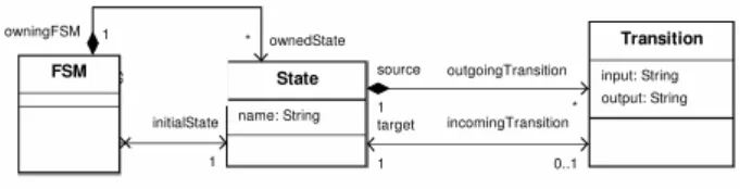
Figure 1. Structure for the FSM metamodel
or Ecore [5]. These languages enable the definition of do-main specific concepts and the relationships between theses concepts (association, composition, specialization). There exist tools that can then check that models, instances of a metamodel, conform to the structure defined by the meta-model. This consists in checking that the model is a set of objects which super class is defined in the metamodel, and the relationships between the objects conform to the rela-tionships defined in the metamodel. Currently, most meta-models are defined with these languages and thus define only the structure of the models (what concepts they can use and how they can be related). For example, Figure 1 describes the structure for finite state machines: a FSM is composed of a set of states that have a set of outgoing and incoming transitions. However, such a definition lacks in-formation about the semantics of FSM.
It is possible to use constraint languages such like the OCL [16] to add semantic constraints on the structure of the metamodels. For example, in Figure 1, it would be possible to use OCL to constrain the initial state to be included in the setownedStatesof the FSM. However, the constraints define static semantics and OCL is not meant to be used for defining the operational semantics of the models.
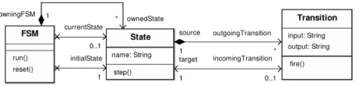
In order to improve the definition of metamodels, it is necessary to add actions. This is called executable meta-modelling. The models that are instances of the metamodel can be executed which enables the validation of the opera-tional semantics through simulation. For example, Figure 2 defines operations in the FSM metamodel. With an action language, it is possible to define the body of these opera-tions. For example, write the sequence of actions that spec-ifies thestep()operation: if an input event matches the input event of an outgoing transition for the current state, then the transition can be triggered and the current state is updated. It is then possible to create a FSM that conforms to this metamodel and call the step run operation on the in-stance of the FSM class to simulate the FSM.
The main benefit of executable modelling is that a model that conforms to the metamodel is executable by construc-tion. In other words, it is not necessary to translate/com-pile the model into another executable language to simulate its behaviour. This is a valuable mechanism both for the modellers and the metamodellers. For the modellers, this
Figure 2. Executable FSM metamodel
provides a rapid feedback to validate the models. For the metamodellers, this simplifies the fine-tuning of the opera-tional semantics of a modelling language: when simulating a model, if the behaviour does not conform to the expecta-tions of the metamodellers, it is possible to modify the op-eration in the metamodel and directly run the same model again. This gives immediate feedback to the metamodellers about the changes they made.
2.2
Kermeta Metamodelling Language
Kermeta [9] is an open source metamodelling environ-ment that has been designed as an extension to the meta-data language EMOF [15] with an action language for spec-ifying semantics and behaviour of meta-models. The action language is imperative and object-oriented and is used to provide an implementation of operations defined in meta-models. A more detailed description of the language is pre-sented in [12].
The Kermeta action language has been specially de-signed to process models. It includes both OO features and model specific features. Convenient constructions of the Object Constraint Language (OCL) such as closures (e.g. each, collect, select) are also available in Kermeta. The ac-tion language offered by Kermeta is well adapted to model-oriented activities such as:
• specification of abstract syntax, static semantics (with the support for OCL) and dynamic semantics,
• model and metamodel simulation and prototyping,
• model transformation,
• aspect weaving.
For example, Figure 3 displays the definition of thestep
operation with the Kermeta language in the FSM meta-model.
In this work, we use Kermeta both to add operations in our requirements metamodel and to define a sequence of model transformations from an input textual language to-wards this metamodel.
o p e r a t i o n s t e p ( c : S t r i n g ) : S t r i n g v a r v a l i d T r a n s i t i o n s : C o l l e c t i o n < T r a n s i t i o n > v a l i d T r a n s i t i o n s : = o u t g o i n g T r a n s i t i o n . s e l e c t { t | t . i n p u t . e q u a l s ( c ) } i f v a l i d T r a n s i t i o n s . s i z e > 1 t h e n r a i s e N o n D e t e r m i n i s m .new end r e s u l t : = v a l i d T r a n s i t i o n s . one . f i r e
Figure 3. Kermeta definition of thestep op-eration
3
A metamodelling environment for
require-ments analysis
To experiment the application of MDE techniques for requirements engineering, we have developed a prototype around an executable requirements metamodel. This meta-model is the core element for our experiments. It is de-fined from the experience we had with modelling require-ments for THALES and France Telecom. The metamodel specifically targets the definition, analysis and validation of functional requirements that define sequences of service ac-tivations. These requirements are expressed as use cases associated with pre and post conditions. The pre-condition defines the conditions in which a use case can be executed and the post condition expresses the effect the use case has on the state of the system. The requirements also manipu-late data (the business concepts) that have to be part of the model. The metamodel presented here captures the differ-ent concepts needed to model these requiremdiffer-ents.
We illustrate the metamodel using examples from a Li-brary Management System(LMS) which requirements are described below:
• A library is maintained by a librarian.
• The librarian can register new books in the LMS and can also register books that have been fixed.
• The librarian can register customers.
• A customer must register in the library to avail the fa-cility of borrowing the books.
• Books must be registered before they are available to the customers.
• The customer can borrow books if they are available and not damaged.
• When a customer returns the book, the book is not available for any customer to borrow again, till the li-brarian performs an inventory check.
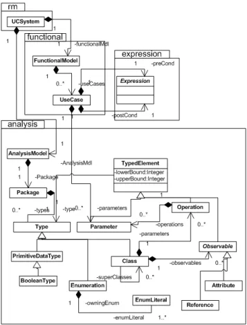
Figure 4. Requirement metamodel overview Figure 4 displays a general view of the metamodel.
UCSystemis the root class for the metamodel and is com-posed of the two main parts of the model i.e. the FUNC-TIONALMODELand theAnalysisModel. The first one specifies use cases with contracts and the latter the static analysis data model for the requirements. This metamodel captures the dynamic part of the requirements, but is not sufficient to capture the static part and in particular the han-dled data. We are aware that the metamodel should be ex-tended for a better support of requirements, however the work presented here yet provides significant benefits, in par-ticular using the simulation process explained in the next section.
TheUseCaseclass represents a use case in our model and each use case has exactly one pre-condition and one post-condition. Contracts allow the system designer to
specify both when a use case is applicable (precondi-tion), and the effect of a use case execution on the sys-tem’s state (post-condition). Contracts, represented by the
Expression class in our metamodel, are expressed as first order logical expressions having a set of typed parame-ters, combined with different logical operators. All the nec-essary concepts are present in the metamodel as sub-classes ofExpression, but are not represented here to limit the size of the figure. These expressions are used to describe the properties of the system (an actor state, a business con-cept state etc) at any state during the simulation. These ex-pressions are Boolean expression, thus can be either true or false. Logical operator includes conjunction (and), dis-junction (or), negation (not) and implication. In order to increase the expressiveness, exists and forall quantifiers are also included.
At requirements level, a use case mainly depends on the actors involved and business concepts which it has to han-dle. In our metamodel we treat actors and business concepts as data that can be passed as parameters to the use case. The Parameterclass in theanalysispackage repre-sents this concept. For example, let us consider the use case borrow of the Library Management System.
Use Case borrow(c: customer, b: book)
The parameters of this use case are the customer who wants to borrow the book, and the book to be borrowed. Here
customeris an actor andbookis a business concept. The analysis package models a high-level analysis data model of the system. It defines the concept of class with operations and attributes. This package is close to the UML class diagram metamodel. AClassrepresents an actor or a business concept. It is composed of a set of
Attributes and Operations. Boolean represented by BooleanTypeclass and enumeration represented by
Enumerationclass are supported as primitive data types. There is not support for handling complex data types.
TheBorrowuse case for a Library Management System requires that a customer who wants to borrow the book must be registered and the book she/he wants to borrow must be available and not marked as damaged. After performing the use case Borrow, the book is not available and the cus-tomer has borrowed the book.
Use C a s e Borrow ( b : Book , c : C u s t o m e r ) P r e : r e g i s t e r e d ( c ) and a v a i l a b l e ( b ) and
n o t damaged ( b )
P o s t : r e g i s t e r e d ( c ) and n o t a v a i l a b l e ( b ) and b o r r o w e d ( c , b )
The model for the above use case can be captured in a model that conforms to the metamodel defined here (and given in Figure 4). However, it might be difficult to express
requirements directly in the form of use cases. It is espe-cially difficult to define all the contracts at once. Moreover, it is difficult to estimate if the use cases globally express the expected requirements. In order to validate the global set of requirements, we have added a simulation capability in the metamodel (section 4). To facilitate the definition of re-quirements, we have defined a constrained natural language that enables the definition of requirements as sentences, but that is not presented here.
4
Simulation of the requirements model
Interactive simulation of use cases is a useful way to determine the behavior and correctness of requirements at an early stage of software development process. The requirement analyst can verify whether the requirements model conforms to the system specification. Using a sim-ulation tool allows inconsistencies in contracts and under-specification errors in the requirements to be detected. Properties of the system like invariants can also be verified using model checking techniques.The simulation technique has been proposed in [13] for test generation purpose and was implemented in Java. For the sake of remembrance we summarize the principles for sim-ulation in section 4.1. Then, section 4.2 details how we now leverage executable metamodelling to simulate the require-ments model. We explain how we extend the metamodel of figure 4 to add execution semantics.
4.1
Principles of the simulation
The intuition behind the simulation is to instantiate the use cases, replacing the formal parameters with actual val-ues defined in an initial configuration. We thus need to know all the business entities present in the system for one particular simulation. For example, to deal with two books and two customers, it is necessary to declare (in a RDL file):
b1, b2: book c1, c2: customer
The possible instantiations of the use caseborrow (b:
book, c: customer) are then borrow(b1,c1),
borrow(b1,c2), borrow(b2,c1) and
borrow(b2,c2). The instantiated use cases are in-teractively executed, if their preconditions are satisfied. More formally, the simulation consists in on-the-fly build-ing of a transition system named Use Case Transition System (UCTS). A UCTS is defined by a quadruple (Q,q0, A,,→) where:
• Qis a finite non-empty set of states, each state being defined as a set of instantiated expressions,
• q0is the initial state,
Figure 5. Transition example in the UCTS
• Ais the alphabet of actions, an action being an instan-tiated use case,
• ,→⊆Q×A×Qis the transition function.
A state of the UCTS represents the system’s state at a given stage of execution, in terms of values of the defined logical expressions. Each transition is labeled with an stantiated use case, and represents the execution of this in-stantiated use case. A transition labeled with an instanti-ated use case iuc exists between two states A andB iff the precondition of iuc is satisfied by StateA, i.e. if A
logically implies the precondition of iuc. The execution of iucleads to State B, which corresponds to the state A
modified according to the post-condition ofiuc.
To illustrate this simulation, let us focus on the UCTS ex-cerpt given in Figure 5. From the current state S, when we apply the instantiated use caseborrow (b1, c1), the new current state isS’. To be able to compute the new current state, we have restricted the usage of the postcon-ditions: the postconditions must be deterministic. This re-striction is a limitation, however conditional postconditions can still be expressed, making the condition explicit. As an example, let us consider a use case U(x:X) resulting in the predicate p1 or the predicate p2, depending on a given condition c(x). We do not accept the postcondition “p1 or p2” since it is not deterministic: the condition c(x) does not appear in the post- condition. However, the postcondi-tion can be expressed as follows: “c(x)@pre implies p1 and not c(x)@pre implies p2”1 We have made explicit in this
latter postcondition the condition c(x), the postcondition is thus valid. Simulating the system interactively builds part of the corresponding UCTS. For that purpose, we also need an initial state defining the values of the logical expressions defined in the requirements at the initial stage of the simu-lation.
4.2
The executable requirements
meta-model
In this section we detail how we use executable meta-modelling to implement simulation directly in the ments metamodel. This allows us to simulate the
require-1The suffix @pre positionned after a predicate in a post-condition
means : the value of the predicate before the execution of the use case, this principle with this syntax is taken from the OCL and Eiffel.
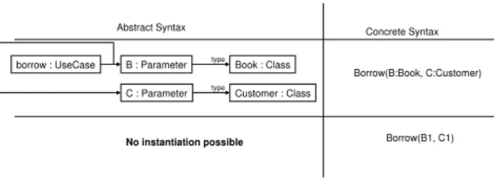
Figure 6. Instantiation issue for use cases
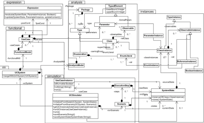
ments and thus to validate the consistency, the complete-ness and the busicomplete-ness logic described in the textual doc-uments. These extensions consist mainly in adding the
simulationandinstancespackages. First, we detail the need for theinstancespackage, then we explain the operations defined insimulation. In addition to these packages, we also add several operations in existing classes. When building a model that conforms to the require-ments metamodel (fig. 4), it is possible to define use cases (as instances of the UseCase metaclass). For example, figure 6 displays an excerpt of an instance of the require-ments metamodel that corresponds to the definition of a use case with two parameters. The right part of the figure gives the concrete syntax for this example. As stated earlier, the simulation manipulates use cases instances. Figure 6 dis-plays the concrete syntax representation of an instance of the borrow use case that we would like to manipulated for simulation. However, EMOF defines only three levels for metamodelling: EMOF, a metamodel and an instance of the metamodel. Thus, it is not possible, in this technological context, to instantiate a use case. As it is shown in Figure 6, the use case definition cannot be instantiated because this definition is an instance of the requirements metamodel. As such, a use case definition is the lowest meta-level that is allowed by MOF.
Since it is not possible to build use case instances, it is necessary to extend the requirements metamod-els with this concept in order to implement simulation. That is introduced in the instances package in Fig-ure 7. It contains classes that define instances of all el-ements necessary to define a use case instance (all sub-classes of ObservableInstance). It also defines a
SystemStateclass that is composed of a set of class in-stances. This means that the state of the system at one mo-ment in the simulation is characterized by the set of values for all objects defined in the requirements. Theclone op-eration is used when running one simulation step: to build the new system state, the current state is cloned and mod-ified according to the use case’s post-condition. An initial system state has to be provided by the user in order to initi-ate the simulation.
The second package that is added for simulation is
simulation (figure 7) that contains the three classes
UCSImulator, Scenario and ExecutionStep
that implement the simulation mechanism. The
UCSimulator defines seven operations used to ini-tialize and run the simulation. The simulation can be initialized either with one system state provided by the user (initializeFromState) or with a sce-nario that has been saved from a previous simulation (initializeFromScenario). In the latter case, the simulator runs the sequence of use cases specified by the scenario. The current state reached at the end of the sequence is the initial state for the new simula-tion. The three operations run, runUCInstance, and
getUCInstances implement the simulation. The op-eration getUCInstancescomputes the set of use case instances that can be executed according to the current state of the system (the current state implies the pre-condition for the use case). The operationrunUCInstancecomputes the new system state resulting from the execution of a given use case instance. Then it updates the current state with this new state. At last,runis the main operation for the simulation. At each step, it callsgetUCInstances, waits for a user input who chooses the use case to execute among the set of possible use case instances, and calls
runUCInstancewith the chosen instance.
In addition to these two packages, we defined opera-tions in the Expressionclass. Theevaluate opera-tion checks whether the expression evaluates to true in the context of the system state it receives as a parameter. The
updateoperation updates the provided state in order for the expression to evaluate to true. All the packages, classes and operations added into the requirements metamodel have been implemented with Kermeta [9].
5
Related work
Recent tools for requirements analysis tend to define a core model that represents the captured information. Sev-eral inputs are used to populate the core model, like con-strained natural languages and graphical languages (UML etc.). The core model is then transformed into one or several output models suitable for properties checking tool.(like SPIN [8] used in [10], FMONA [3] used in [2]). The Dwyer patterns [7] are a good example of the need for a unified ap-proach. The intuition behind these patterns is that, there exists a lot of different formalisms (often one formalism for one tool), while the concepts manipulated by these for-malisms are restricted. These patterns thus provide a core model for analysis of requirements using temporal logic. In the same way, we have defined our own core metamodel for functional requirements.
Although the implementation of these tools deal with different types of models, they do not use the MDE
tech-Figure 7. Extended metamodel for requirements simulation
niques. In [6], a metamodel is proposed to capture require-ments of real-time system. The models are obtained using syntactical patterns: textual requirements are written, that strictly respect the syntactical patterns. The benefits of such an approach is that the sentence structures that have been chosen for the syntactical patterns impose to disambiguate the requirements (our approach also benefits from this dis-ambiguation). However, the classes of the metamodel are manily composed of attributes of type String. In other words, when the requirements are parsed using the syntacti-cal patterns, all the word groups that are not part of a pattern (for example : the subject of an action, or the condition to perform an action) are not interpreted and treated as Strings. That means that the obtained model cannot possibly be pro-grammatically handled for example for a simmulation. Of course the requirements are more easily written than with our approach, but in the other hand they can hardly be val-idated with automated process, and they cannot either be used for test generation purpose.
Concerning requirements analysis, authors of [10] present an integrated tool suite called SPIDER. It allows users to specify UML Models for analysing temporal be-havioural properties of the model. The tool is especially dedicated to analyse systems whose implementation fol-lows the MDA principles. MDA [14] advocates the use of models and model transformations in order to separate
busi-ness and application logic from the underlying technologi-cal platform. The properties are expressed in a constrained natural language (like the DNL of [17]) whose accepted sentences match well the Dwyer temporal logic patterns [7]. In the same way we define a constrained language called RDL and a transformation towards a requirement model, thanks to interpretation patterns. Besides analysis, other works aim at generating test cases from requirements. In particular, several approaches [4, 1, 13] use requirements expressed with extended use cases to generate test cases or at least test objectives. This kind of work shows the benefits that are obtained when the requirements take the form of use cases and emphasizes the need for validated use cases, for example using the simulation mechanism we propose. In the same vein of test generation from require-ments, the authors of [2] propose a tool suite called RETNA, which provides analysis and test case generation from re-quirements expressed in terms of natural language. Simi-lar to our approach, their internal model is based on state machines. The implemented test criterion is robustness (re-jection paths), while we implement more possibilities (ro-bustness and nominal behavior). The test criteria we have implemented are explained in [13].
6
Discussion and Conclusion
Model-driven engineering (MDE) offers a new approach for software development, which considers models as first class entities. The work presented here applies it to requiments engineering. We have proposed a metamodel for re-quirements and extended it to add the semantics with Ker-meta. This executable metamodel provides capabilities to model and simulate requirements. We have also developed a series of model transformations that generates a require-ment model from a constrained natural language, which is not presented here. The initial intent of this work is to study whether MDE techniques offer good solutions to unify RE activities (agreeing, modelling, simulating...). To evaluate this intuition, the requirements metamodel and the RDL have been experimented to model requirements with THALES Airborne System (TAS) components and France Telecom. The case studies for TAS concerned two sys-tems components of last generation combat aircrafts, of mid-complexity (around 5-15 C++ KLOC). France Telecom studies concerned three services for the LiveBox modem. The goal was to simulate these services and validate func-tional requirement documents. The following observations were drawn:
• The current metamodel captured most of the concepts needed to express the requirements we had to deal with.
• Simulation is an efficient to reveal underspecifications in requirements. For example, it easily revealed that services that should have been available at one point in the simulation were not available (revealing errors in contracts).
These initial observations are very encouraging to consider our prototype as a good solution to model requirements and simulate the behaviour for validating and agreeing the re-quirements. These results need to be confirmed with ad-ditional case studies. Of course, our metamodel does not allow to capture any requirement : it captures efficiently the dynamic part of the requirements, but not the static part, including the handled data. As future works, we plan to enhance this metamodel (or create another dedicated meta-model) to capture static aspects. We also want to add model transformations that can extract particular views on the model (such as a UML model) and that improve the traceability between the requirements and the implementa-tion.
References
[1] F. Basanieri, A. Bertolino, and E. Marchetti. The cow_suite approach to planning and deriving test suites in UML
projects. In J.-M. Jézéquel, H. Hussmann, and S. Cook, ed-itors,UML 2002 - The Unified Modeling Language. Model Engineering, Languages, Concepts, and Tools. 5th Interna-tional Conference, Dresden, Germany, September/October 2002, Proceedings, volume 2460 ofLNCS, pages 383–397. Springer, 2002.
[2] R. Boddu, L. Guo, S. Mukhopadhyay, and B. Cukic. Retna: From requirements to testing in a natural way. InRE04 (Requirements Engineering), pages 262–271, Kyoto, Japan, 2004.
[3] J.-P. Bodeveix and M. Filali. Fmona: A tool for express-ing validation techniques over infinite state systems. In Springer-Verlag, editor,Proceedings of the 6th International Conference on Tools and Algorithms for Construction and Analysis of Systems: Held as Part of the European Joint Conferences on the Theory and Practice of Software, ETAPS 2000, pages 204–219, 2000.
[4] L. Briand and Y. Labiche. A UML-based approach to system testing. Journal of Software and Systems Modeling, pages 10–42, 2002.
[5] F. Budinsky, T. Grose, D. Steinberg, R. Ellersick, E. Merks, and S. Brodsky. Eclipse Modeling Framework: a devel-oper’s guide. Addison-Wesley Professional, 2003.
[6] C. Denger, D. M. Berry, and E. Kamsties. Higher qual-ity requirements specifications through natural language pat-terns. InSWSTE ’03: Proceedings of the IEEE International Conference on Software-Science, Technology & Engineer-ing, page 80, Washington, DC, USA, 2003. IEEE Computer Society.
[7] M. B. Dwyer, G. S. Avrunin, and J. C. Corbett. Patterns in property specifications for finite-state verification. In I. C. S. Press, editor,ICSE, pages 411–420, 1999.
[8] G. Holzmann. The model checker spin. InIEEE TSE, pages 279–294, 1997.
[9] Kermeta. The kermeta project home page, 2005.
[10] S. Konrad and B. H. C. Cheng. Automated analysis of natural language properties for uml models. In MoD-eVa’05 (Model Design and Validation Workshop associated to MoDELS’05), Montego Bay, Jamaica, 2005.
[11] D. Lugato, F. Maraux, Y. Le Traon, C. Nebut, V. Normand, H. Dubois, J.-Y. Pierron, and J.-P. Gallois. Automated func-tionnal test case synthesis from thales industrial require-ments. InRTAS’04, Toronto, Canada, 2004.
[12] P.-A. Muller, F. Fleurey, and J.-M. Jézéquel. Weaving ex-ecutability into object-oriented meta-languages. In MoD-ELS’05, pages 264 – 278, Montego Bay, Jamaica, 2005. LNCS.
[13] C. Nebut, F. Fleurey, Y. Le Traon, and J.-M. Jézéquel. Au-tomatic test generation: A use case driven approach. IEEE Transactions on Software Engineering, 2006.
[14] OMG. Mda, 2003.
[15] OMG. Mof 2.0 core final adopted specification., 2004. [16] OMG. Object constraint language specification, version 2.0,
2006.
[17] R. L. Smith, G. S. Avrunin, L. A. Clarke, and L. J. Osterweil. Propel: An approach supporting property elucidation. In A. Press, editor,ICSE, pages 11–21, 2002.
[18] Sommerville. Integrated requirements engineering: A tuto-rial.IEEE Software, 22(1):16 – 23, 2005.