Edison vs Tesla: A rematch in the telecom data center
Paul Smith
Technical Marketing Manager GE – Critical Power
Plano, TX USA [email protected] Abstract — For over a century, since the invention of the
telephone, the telephone network has relied on DC Power and has used DC battery reserve to provide "continuous dial tone", even during commercial power outages. The debate between proponents of George Westinghouse's AC and Thomas Edison’s DC commercial power distribution schemes has raged just about as long as the telephone has existed. The debate over the use of AC and DC Uninterruptible Power Supplies (UPS's) is more recent. Powering Telecommunications equipment has long been dominated by DC UPS's while Computer equipment has traditionally been backed up by AC UPS's.
The metamorphosis of telecommunications networks into Information and Communications Technology (ICT) networks with their reliance upon digital technologies has blurred the distinction of these systems and the choice of UPS technology reflects this. Changing requirements and advances in battery chemistries, power system efficiencies and software controls are all affecting choice of power system architecture.
This paper examines the changing requirements of ICT network equipment and their effect on the various AC and DC UPS architectures that are available to power them. Changing requirements have opened up opportunities for different power architectures utilizing new battery chemistries, while advances in power conversion equipment allow power systems to be placed in different locations, improving distribution efficiency. Continuous pressure for operational cost reduction is fueling the need for more efficient "end to end" systems, as well as reducing capital costs of equipment. Total Cost of Ownership (TCO) is now a key ingredient in the choice of power architecture alongside the questions of reliability, availability, reserve time, redundancy and scalability. The impact of all these key ingredients is examined.
This paper examines these advances with a view to better understanding the trends in power architectures and implementation. This may also allow us a glimpse into the "crystal ball" of future developments and trends.
Keywords—AC UPS; DC UPS; Rectifier; Power; Efficiency; Phase Balance; Data Center
I. DCUPS
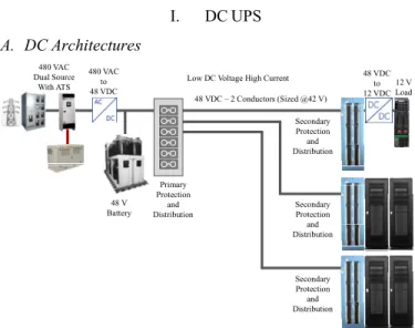
A. DC Architectures
Figure 1 – Classic DC UPS Architecture
The DC UPS as depicted in Figure 1 has been used to power telecom systems since the invention of the telephone early in 1870’s.
Telecom central offices have traditionally been required to provide 4-8 hours of battery reserve, depending on the availability of a generator and specific regulatory
requirements. Many of today’s telephone switching offices have gradually morphed into data centers, which may or may not require eight hours of power reserve. Some equipment is still subject to regulatory compliance and may still require 8-24 hours of backup power between batteries and generators. Much of the data center equipment however may not require this length of reserve time, especially if service can be
maintained through spatial redundancy of server operations. It may only be necessary to have 10-15 minutes of reserve power to allow transfer of server operations, or to allow generator(s) to start and synchronize their operation.
B. Rectifier Advances
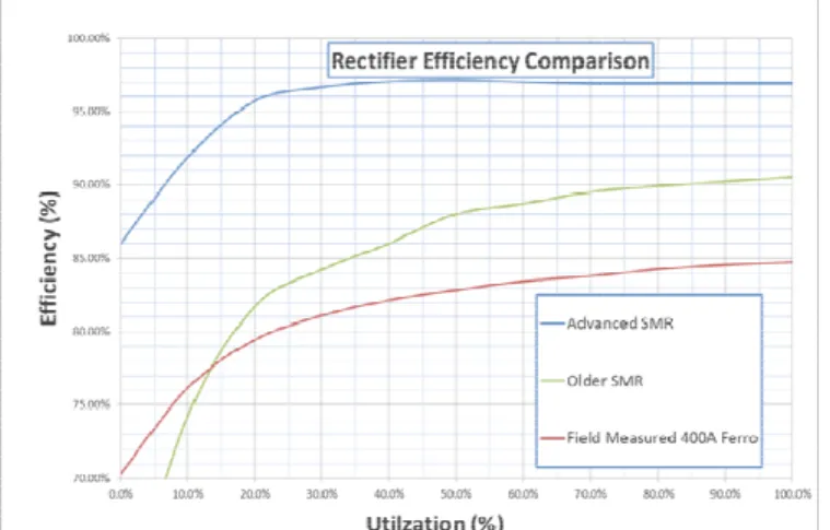
Rectifier technology has made tremendous improvements over the last few decades, with rectifier sizes reduced by one to two orders of magnitude. Efficiencies have improved dramatically, with losses reduced by as much as 75%. This is illustrated in Figure 2
Low DC Voltage High Current
4 12 V Load 480 VAC Dual Source With ATS 480 VAC to 48 VDC 48 VDC – 2 Conductors (Sized @42 V) 48 V Battery 48 VDC to 12 VDC Primary Protection and Distribution Secondary Protection and Distribution Secondary Protection and Distribution Secondary Protection and Distribution
Figure 2 - Rectifier Advances
Figure 3 illustrates a direct compariso Switch Mode Rectifier (SMR), older genera Ferro Resonant Rectifier efficiency performanc
Figure 3 – Rectifier Efficiency Comparison C. Battery Advances
Advances in battery chemistry are also tran significant reductions in battery size and weigh acid batteries providing 8 hours have traditiona in the basement of large switching offices beca size and weight.
It can be seen in Figure 5 that advanced bat are capable of providing a two to eight times re volume and weight.
Figure 4 - Battery Types and Chemistries
1970 1990 2008
Ferro 200A SMR 220A (Gen 1) SMR 220A (Gen 2) Volume:14,400 in3 Volume: 2,883 in3 Volume: 1,668 in3
Density:0.8 W/in3 Density: 4.42 W/in3 Density: 7.64 W/in3
Weight:725 lb. Weight: 59 lb. Weight: 50.5 lb.
Efficiency: 88% Efficiency: 92% Efficiency:96%
Flooded VRLA Ni-Cd Li-Io
Flooded Lead Acid Valve Regulated Lead Acid “Sealed”
Nickel Cadmium Lithium Ion
on of Advanced ation SMRs and ce.
nslating to ht. Flooded lead ally been located ause of the their
ttery chemistries eduction in both
Figure 5 – Battery Density and Chemistries
With reduced reserve time requir battery technologies, it now become power equipment on the upper floor expectation that the average floor is This has enabled the development o (distributed) DC UPS architectures
Figure 6 – Distributed DC UPS Architecture
This architecture takes advantag both rectifiers and batteries to place lineup with sections of the load equi architecture include:
Efficiency - By moving power c load, DC distribution losses are dram are replaced by much smaller AC lo voltage and lower current of the AC improves the “end-to-end” efficienc reduction in a facility’s OpEx.
Copper Cable - The reduced di voltage has to travel requires many carrying current over much reduced enormous reductions in CapEx requ the copper cable.
Cooling - Similarly, improveme efficiency will reduce wasted energy Improvements in efficiency also red the power conversion equipment, w load on the HVAC system, further r
2014 SMR 100A (Gen 3) Volume: 218 in3 Density: 26.6 W/in3 Weight: 4.1 lb. Efficiency: 97% n Na-Ni-Cl n Sodium Nickel Chloride Battery 0 100 200 300 0 50 100 150 200 G ravim et ri c Ener gy Density (W h/ kg) Volumetric Energy D Lead Acid Ni-CD Ni-MH Li-Polym Na-Ni-Cl AC Voltage 480 VAC Dual Source With ATS Primary Protection and Distribution
rements and advanced es practical to put reserve rs with a reasonable s capable of supporting it. of some alternative
as shown in Figure 6.
e of the smaller sizes in e smaller DC UPS’s in the
ipment. Benefits of this conversion closer to the
matically reduced. They osses, due to the higher C distribution system. This
cy and will result in a istance that the lower DC
times smaller conductors d distances, resulting in uired to purchase and install
nts in conversion
y and further reduce OpEx. duce the heat dissipated in which in turn reduces the
reducing OpEx. 400 500 600 Density (Wh/l) H Li-ion mer 3 12 V Load 48 VDC to 12 VDC
Flexible Energy Reserve - By distributing the power conversion equipment to feed a portion of the load equipment, it is possible to provision reserve time appropriate to that set of load equipment. This means that if one load needs a longer reserve time, it can be provisioned without encumbering the entire facility with the cost of the longer reserve time. The reserve time can be matched to the load in appropriate increments.
Reliability – Grouping smaller loads with smaller power plants decreases the size of a given failure group, due to power issues, resulting in an overall increase in reliability.
Scalability – Power equipment is added incrementally along with load equipment, minimizing initial power equipment and installation costs (CapEx).
II. AC UPS
The AC UPS has also been around for many years,
supporting AC powered equipment by cleaning up poor quality utility AC and riding through utility AC outages.
The representation in Figure 7 is drawn in a way intended to highlight the similarity with the Classic DC UPS shown in Figure 1, it does not show elements such as bypass or dual corded loads frequently utilized.
A. AC Architectures
Figure 7 – Classic AC UPS Architecture B. Redundancy Strategies in AC UPS
Most AC UPS’s are constructed as high power blocks, not utilizing the redundant rectifier type of architecture found in most DC UPS systems.
Redundancy and the associated improvement in reliability are incorporated into AC UPS systems at the block level as shown by some of the examples in Figure 8.
Illustrated are:
1. The full System + System, where one complete system
(3 blocks) is redundant.
2. A catcher system, where a single block is redundant,
and switched to support any module that fails.
3. A redundant parallel configuration, where N+1 blocks
operate in parallel.
Each of these strategies has its own strengths and
weaknesses and may be appropriate for different applications, depending on needs.
Figure 8 – Redundancy in AC UPSs
A detailed study of the different redundancy strategies is the subject of a separate paper. [1]
III. ALTERNATIVE UPSARCHITECTURES A. High Voltage DC Architecture
In the architectures shown so far, power has to be transferred from one place to another at some electrical voltage. In the DC architecture of Figure 1 power is moved from the central power plant to the load location at 48VDC. When the load power level is high this can introduce significant losses, since the current will be high. High currents require large copper conductors to minimize losses. The cost of copper makes the Capital Expense (CapEx) high to keep losses low.
If the power were transferred at a higher voltage the conductors could be significantly smaller for the same loss level, and CapEx reduced. At 380VDC the currents are 12.6% of those required at 48VDC for the same power.
Figure 9 shows the equivalent of the centralized 48VDC UPS scaled to 380VDC.
Figure 9 – High Voltage DC UPS Architecture
Losses in the conductors will be lower because of the higher voltage, but losses in the converter blocks will be similar because we have not eliminated any conversions, there Low AC Voltage High Current
2 12 V Load 480 VAC Dual Source With ATS 480 VAC to 550 VDC 240 VAC – 2 Conductors Battery 48 VDC to 12 VDC Primary Protection and Distribution Secondary Protection and Distribution Secondary Protection and Distribution Secondary Protection and Distribution 550 VDC to 240 VAC System + System Redundant Parallel (N+1) Catcher System
High Voltage DC Low Current Small Cables Low Losses
380 V Battery 380 VDC – 2(3) Conductors 480 VAC to 380 VDC 12 V Load 380 VDC to 12 VDC Protection and Distribution 480 VAC Dual Source With ATS
are still 2 major conversion stages; the rectifier and downstream DC/DC converter.
B. High Voltage AC Architecture
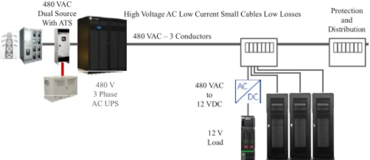
Transferring power from the input switch gear to the load cabinet at 480VAC has the same, or better, improvement in losses as high voltage DC, the architecture looks like that shown in Figure 10. The rectifier stage and battery are now moved all the way downstream to the load cabinet. This is made possible by the aforementioned improvements in rectifier and battery technologies. Designing the rectifier to accept 480VAC 3 phase power and output 12VDC directly removes a conversion step from the end to end power train, further reducing losses.
Figure 10 – High Voltage AC Architecture
This architecture is a logical progression from the distributed DC architecture of Figure 6, which moved the rectifiers close to the load, in a cabinet at the end of a row of load cabinets.
In this case the rectifier moves all the way into the load cabinet, further reducing the distance from the rectifier to the load, and the losses associated with that low voltage loop. We have changed the rectifier output from 48V to 12V also, which removes the need for an additional DC /DC conversion step, but has a consequence within the cabinet:
The low voltage loop within the cabinet is now 12V rather than 48V, so the currents are proportionally higher, this warrants paying some attention to minimizing the distance between rectifier and load even within the cabinet.
C. Optimizing within the Cabinet
Installing the rectifier inside the load cabinet has been conventionally done by mounting in the top or bottom of the cabinet space, as shown in Figure 11
The distance from the power unit to the farthest load shelf may be as much as 7 ft with this arrangement, and the 12V cables or bus bars must be sized to keep the voltage drop within the load’s acceptable limits under worst case
conditions. Worst case conditions for voltage drop are when the unit is operating from the battery, when the battery voltage has depleted to its lowest value.
Figure 11 – High Voltage AC Architecture – Load Cabinet
Depending on the total load in the cabinet, and the size of the rectifier, it may be advantageous to split the power and battery shelves into blocks which are spread throughout the cabinet, as shown in Figure 12. This significantly reduces the maximum distance between rectifier / battery and associated load.
Figure 12 – High Voltage AC Architecture – Horizontal
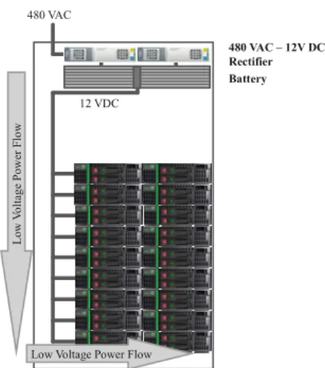
In cabinets with space on the side, or if this can be engineered in to the cabinet, the arrangement in Figure 13 can further reduce the distance travelled by the 12VDC power. In this vertical arrangement, 12V power flow in the vertical dimension of the power shelves is minimized, since each rectifier feeds to a horizontally adjacent load, vertical flow is limited to that which is needed to balance load between adjacent rectifiers.
High Voltage AC Low Current Small Cables Low Losses 480 VAC – 3 Conductors 12 V Load 480 VAC to 12 VDC Protection and Distribution Battery 480 VAC Dual Source With ATS Lo w V oltag e P ower F lo w
Low Voltage Power Flow 480 VAC 12 VDC 480 VAC – 12V DC Rectifier Battery 480 VAC Lo w V olta ge Po w er Flo w 480 VAC – 12V DC Rectifier Battery Low Volta ge Po w er Flo w Lo w V olta ge Po w er Flo w
Figure 13 – High Voltage AC Architecture – Vertical (Ed
IV. AN OPTIMIZED CABINE
Figure 14 – Cabinet designed to accomadate vertical “Edg
The “Edge” cabinet shown in Figure 14 is power distribution unit (PDU) in the left side, 480VAC at the top, and has slots to accept rec or other power modules as needed. Key featur
1. 480V AC input (or 380VDC) contained
PDU, enclosed for safety of personnel
2. Energy Storage Near Load
3. Turnkey Solution with 42U of Usable S
4. Flexibility of load voltage
5. Flexibility of reserve time
6. Flexibility of cooling (load and power s
7. Infrastructure for load shelves to plug in
8. DC voltage determined by rectifier, 12V
9. Cabinet can be factory integrated for qu
480 VAC
480 VAC – 12V DC Rectifier
Battery
Low Voltage Power Flow
Low Voltage Power Flow dge) ET ge” power. fitted with a which accepts ctifiers, batteries res include: d within the Space separate) n to DC bus V, 48V etc uality A. Cabinet or PDU?
The PDU shown in the left side o fit in many types of cabinet, or can b customized cabinet.
Figure 15 – The “Edge” PDU and a cabinet i
One of the key advantages of thi to place cabinets with different load and DC) in the same line up, efficie 480VAC source.
B. 12V DC powered loads
Load equipment that can accept the optimum power processing by a number of conversion stages, one.
The use of 12VDC around the ca design because of the relatively high this voltage. The use of the vertical proposed minimizes conduction loss
C. 48V legacy equipment compati
While we have seen that convers 3 phase to 12VDC is optimal for mi number of conversion steps and con be occasions where the load equipm traditional -48VDC. This is easily a rectifiers and battery modules in the design. This has the advantage of lo cabinet, but there will be another po shelf to transition from 48VDC to th
D. AC output from inverter in same
Inclusion of an inverter in one of effectively converts the cabinet pow AC UPS, housing rectifier, battery a space. This allows simple mixing o differing requirements, in this case A this introduces more power convers powering of legacy AC loads in the loads.
E. Phase Balance
Data center loads traditionally po present phase balance issues to the f
“Edge” Single Row PDU “Edge” Si
of Figure 15 is designed to be designed in to a
implementation.
is architecture is the ability d voltage requirements (AC
ntly fed from the same
12VDC directly provides allowing the minimum
abinet requires careful h current levels required at l edge mounted PDU
ses.
ibility
sion directly from 480VAC inimizing the overall nduction losses, there may ment still requires the
accommodated using 48V e same “Edge” cabinet
ower currents in the ower conversion in the load
he final voltage (12V).
e space – UPS in a box.
f the “Edge” slots
wer infrastructure to a mini and inverter in the edge of load cabinets with
AC powered loads. Again ions, but does allow the
same line up with DC
owered by single phase AC facility operator, since the ingle Row PDU – installed in a cabinet
balance. This is a significant burden as the data center grows and loads are added.
The use of a true three phase rectifier eliminates this issue by automatically balancing the load between phases every time additional load and rectifiers are added.
F. Energy Reserve in an AC UPS
We have shown how the battery can be moved all the way to the load cabinet, and while this offers several advantages, including reserve time flexibility, cabinet to cabinet, there are applications where it may be more appropriate to use the centralized AC UPS previously discussed.
Figure 16 – AC UPS feeding a single conversion step architecture.
Figure 16 shows the combination of a centralized AC UPS with the 480VAC to the load concept. Here the reserve is supplied by a centralized AC UPS system (the user can choose a redundancy scheme from Section II.B ) If the UPS is operated in bypass mode we still retain the single conversion step.
Battery capacity using AC UPSs is typically short (minutes) and will be the same for all loads using this centralized architecture, however the battery reserve does not take up valuable space in the load cabinet.
G. Energy Reserve in a High Voltage DC UPS
If a longer battery reserve is required for all equipment, then the centralized high voltage DC architecture may be appropriate, combining the advantages of high voltage power distribution with the optimized cabinet layout, as shown in Figure 17. The optimized cabinet would be equipped with 380VDC to 12VDC or 48VDC converters in this
implementation.
Figure 17 – High Voltage DC UPS Architecture with Edge load cabinet
V. CONCLUSIONS
Advances in rectifier technology, size and efficiency, battery chemistry and size, and changing reserve time
requirements have converged to allow changes in power architectures not previously practical.
The use of a rectifier that converts 480VAC three phase directly to the dc voltage required at the load, combined with an innovative load cabinet layout, minimize the losses from both conduction and conversion. The result is a low initial cost and low ongoing operating cost.
This architecture ensures phase balance on the AC supply without owners having to manage or assign loads to individual phases, and allows flexibility in the provision of energy reserves.
The inclusion of appropriately sized power infrastructure in the load cabinet itself also allows cost minimization and scalability at an unprecedented level.
The optimized cabinet is also capable of supporting a high voltage DC input and additional load configurations for different applications including a variety of DC and AC loads enabling the support of transport equipment, data center loads and legacy equipment.
ACKNOWLEDGMENTS
The author would like to thank the following inventors [2] for creative input and assistance in preparing and proof reading of this paper:
Ed Fontana Mike Steeves
Mark Johnson Bob Burditt
Roy Davis Steve Stein
REFERENCES
[1] GEA-D1005 - Redundant Parallel Architecture(RPA) for UPS systems -
http://apps.geindustrial.com/publibrary/checkout/GEA-
D1005?TNR=Data%20Sheets%7CGEA-D1005%7CPDF&filename=GEA-D1005-GB.pdf
[2] Patents Pending:
Systems and methods for power conversion and distribution (2014) Integrated power racks and methods of assembling the same (2014) .
High Voltage AC Low Current Small Cables Low Losses 480 VAC – 3 Conductors 12 V Load 480 VAC to 12 VDC Protection and Distribution 480 VAC Dual Source With ATS 480 V 3 Phase AC UPS
High Voltage DC Low Current Small Cables Low Losses
380 V Battery 380 VDC – 2(3) Conductors 480 VAC to 380 VDC 12 V Load 380 VDC to 12 VDC Protection and Distribution 480 VAC Dual Source With ATS