3D Beamforming for Wireless Data Centers
Weile Zhang
§, Xia Zhou, Lei Yang
†, Zengbin Zhang, Ben Y. Zhao and Haitao Zheng
Department of Computer Science, U. C. Santa Barbara, USA
§
Xi’an Jiaotong University, Xi’an, P. R. China
†Intel Labs, Hillsboro, OR, USA
[email protected], [email protected], {xiazhou, zengbin, ravenben, htzheng}@cs.ucsb.eduABSTRACT
Contrary to prior assumptions, recent measurements show that data center traffic is not constrained by network bisec-tion bandwidth, but is instead prone to congesbisec-tion loss caused by short traffic bursts. Compared to the cost and complexity of modifying data center architectures, a much more attrac-tive option is to augment wired links with flexible wireless links in the 60 GHz band. Current proposals, however, are severely constrained by two factors. First, 60 GHz wire-less links are limited by line-of-sight, and can be blocked by even small obstacles between the endpoints. Second, even beamforming links leak power, and potential interference will severely limit concurrent transmissions in dense data centers. In this paper, we explore the feasibility of a new wireless primitive for data centers,3D beamforming. We explore the design space, and show how bouncing 60 GHz wireless links off reflective ceilings can address both link blockage and link interference, thus improving link range and number of current transmissions in the data center.
Categories and Subject Descriptors
C.2.1 [Computer-Communication Networks]: Net-work Architecture and Design
General Terms
Design, Performance
Keywords
Wireless data centers, beamforming
1.
INTRODUCTION
To alleviate perceived changes in data center network traffic patterns due to distributed computing systems such as MapReduce and Dryad, recent work has pro-posed alternatives to the standard hierarchical data
cen-Permission to make digital or hard copies of all or part of this work for personal or classroom use is granted without fee provided that copies are not made or distributed for profit or commercial advantage and that copies bear this notice and the full citation on the first page. To copy otherwise, to republish, to post on servers or to redistribute to lists, requires prior specific permission and/or a fee.
Hotnets ’11,November 14–15, 2011, Cambridge, MA, USA. Copyright 2011 ACM 978-1-4503-1059-8/11/11 ...$10.00.
ter network that increase pair-wise throughput capac-ity [6, 9, 12, 13, 14]. While each solution achieves full bisection bandwidth, each requires significant changes in data center hardware and the network stack.
More recently, traffic measurement studies have made surprising observations on the real traffic requirements of data center applications [10, 11, 16]. Specifically, these measurements show that current data workloads fall far short of full utilization on data center networks, and that congestion loss, when it occurs, is sporadic, difficult to predict, and often the result of short-lived bursts at links with relatively low utilization [10].
These results imply that instead of drastically alter-ing the data center architectures, network managers are better served augmenting existing systems with flexible point-to-point links. One possibility is to utilize high-throughput, beamforming wireless links in the 60 GHz band. The 60 GHz band is unlicensed,provides multi-Gbps data rates, and can be implemented using rela-tively low-cost hardware. Finally, because 60 GHz sig-nals attenuate quickly with distance, multiple wireless links can be deployed in a single data center.
Current work is exploring the effectiveness of 60 GHz links in data centers as easily reconfigurable links that can alleviate traffic hotspots [15, 17]. However, these systems have significant limitations. First, even beam-forming directional links will experiencesignal leakage, and produce a cone of interference to any receivers near or behind the intended target receiver. This limits the number of links that can be active concurrently in densely occupied data centers, thus reducing the aggregate through-put offered by these wireless links.
Second, these linksrequire direct line-of-sightbetween sender and receiver, and can be blocked by even small objects in the path. This limits the effective range of 60 GHz links to neighboring top-of-rack radios. Given that hotspots occur regularly at both edge and core links [10], augmenting core links would require multi-ple hops through a line-of-sight 60 GHz network. With the use of half-duplex, directional antennas, this leads to greater than 50% throughput drop, along with ad-ditional delays required to frequently adjust antenna orientation.
(a) Rack-based DC (b) Container-based DC (c) 2D Beamforming (d) 3D Beamforming
Figure 1: Radio transceivers are placed atop each rack (a) or container (b). Using 2D beamforming (c), transceivers communicate with neighboring racks directly, but forward traffic in multiple hops to non-neighboring racks. Using 3D beamforming (d), the ceiling reflects the signals from each sender to its desired receiver, avoiding multi-hop relays.
To address these issues, we investigate the feasibil-ity of 60 GHz 3D beamforming as a novel and flexible wireless primitive for use in data centers. In 3D wireless beamforming, a top-of-rack directional antenna forms a wireless link by reflecting a focused beam off the ceiling towards the receiver. This allows it to reduce its in-terference footprint, avoid blocking obstacles, and pro-vides an indirect line-of-sight path for reliable commu-nication. To implement such a system, we only need beamforming radios readily available today, and sim-ple flat metal plates can provide near perfect reflection when mounted on the ceiling of a data center.
3D beamforming has several distinctive advantages over prior “2D” approaches. First, bouncing the beam off the ceiling allows links to extend the reach of radio signals by avoiding blocking obstacles. Second, the 3D direction of the beam significantly reduces its interfer-ence range, thus allowing more nearby flows to transmit concurrently. The reduced interference also extends the effective range of each link, allowing our system to con-nect any two racks using a single hop, and mitigating the need for multihop links.
In this paper, we propose a 3D beamforming system for 60 GHz wireless transmissions in data centers. We describe a detailed design, and use detailed simulations to understand the design tradeoffs of such a system. We quantify the short-term implications of 3D versus 2D beamforming, and discuss key challenges remaining before widespread adoption of this technology. 60 GHz links are a promising tool to augment current data cen-ters with flexible, point-to-point wireless capacity, and we believe this work is an advancement that eliminates some of the obstacles en route to its wide adoption.
2.
WIRELESS DATA CENTERS
Wireless links can address the cabling complexity in data centers [15, 17, 18, 23, 26]. As shown in Fig-ure 1(a)-(b), wireless radios can be placed on the top of each rack or shipping container, connecting the top-of-rack (ToR) switches wirelessly. Despite the potential to enable flexible network configurations and efficient cooling, data center managers are still skeptical on
de-ploying wireless interconnects in practice [1]. In this section, we first describe existing wireless designs for data centers, and then outline their key limitations.
2.1
60 GHz Wireless
Existing designs [15, 17, 18, 26] adopt 60 GHz wire-less technologies because of two reasons. First, the 7GHz available spectrum offers ample opportunity to achievemulti-Gbps data ratesrequired by data centers.
Second, operating at a high carrier frequency, 60 GHz links generate limited interference [29], which is highly beneficial to data centers with dense rack deployments. To enhance link rate and further suppress interfer-ence, 60 GHz links use beamforming [15, 18], a physi-cal layer technique to concentrate transmission energy in desired directions. Recent advances in radio design make 60 GHz beamforming radios readily available and affordable, either as directional (horn) antennas [15] or antenna arrays [4]. They can adjust beam direction in fine-grain [15, 27], either mechanically or electronically.
2.2
Limitations
Despite the advances in radio designs, the use of wire-less still imposes limitations in data center networking. Link Blockage. As shown in Figure 1(c), exist-ing designs and their prototypes only directly connect neighboring racks due to link blockage [15, 18]. Be-cause 60 GHz link has a wavelength of 5 mm, any ob-ject larger than 2.5 mm can effectively block radio sig-nals [25]. Hence for today’s grid-based rack placement, radio transceivers can easily block each other’s signals. These transceivers can also reflect signals, resulting in multipath fading that severely degrades transmission rate [25]. One can reduce link blockage locally by plac-ing racks in hexagons [28]. This, however, leads to inef-ficient space use and cooling problems, and still cannot solve the general link blockage problem.
Restricting wireless connections to neighboring racks means that any extended connection must go through multiple hops. This increases end-to-end delay, reduces throughput, and produces bottlenecks at certain racks that must forward a significant amount of traffic.
0 2 4 6 8 10 12 0 5 10 15 20 25 30 35 40 45 50 Data rate (Gbps) L (m) 2D 3D, h=1 m 3D, h=2 m 3D, h=3 m
(a) Link data rate (b) Interference region, horn antenna (c) Interference region, antenna array
Figure 2: Key properties of 3D Beamforming. (a) Data rate vs link distanceL. (b)-(c) 2D and 3D beamforming signal maps using both horn antenna and antenna arrays. The transmitter is at (0m,0m) and the receiver is at (2m,0m). Radio Interference. While beamforming can bound
the transmission energy in a “narrow” direction, it still creates interference at some receivers. Furthermore, ra-dio design artifacts lead to signal leaked outside of the intended direction [20, 27]. These factors, together with the dense rack deployment, create harmful interference for concurrent links. For example, consider a link using a typical horn antenna with 10o
beam width and 10dBm transmit power. A single link can interfere1
with up to 27 racks in a typical deployment with 160 racks in a 11m×33m area [17].
Radio interference constrains the number of concur-rent links, and thus also network throughput. Separat-ing links in the frequency domain limits link capacity. Alternatively, increasing spacing between racks leads to inefficient space usage.
3.
3D BEAMFORMING
To address the above limitations, we propose3D beam-forming, a new beamforming approach that leverages ceiling reflections to connect racks wirelessly. As shown in Figure 1(d), each sender points its beam towards a point on the ceiling, which reflects the signal to the desired receiver. This creates an indirect line-of-sight (LOS) path between the sender and receiver, bypassing obstacles2
and reducing interference footprint. Next we discuss the feasibility of 3D beamforming, and show how it addresses the limitations of 2D beamforming.
3.1
Feasibility
3D beamforming requires three hardware components: • Beamforming Radios: We reuse today’s
beamform-ing radios [4, 15] and adjust beam directions in both azimuth and elevation either electronically or using
1
We define a rack as interfered with if its perceived interference power is greater than -71 dBm, the noise level defined by the IEEE 802.11ad standard [2].
2
Here we assume that there are no obstacles between top of racks (or containers) and the ceiling.
rotators. Existing rotators can achieve an accuracy of 0.09o
[3], sufficient for our needs.
• Ceiling Reflectors: We mount microwave reflectors on the ceiling such that they act as specular mir-rorsto reflect signals. These reflectors can be flat metal plates, which have been shown experimentally to offer perfect specular reflection without degrading energy or changing path loss characteristics [7, 24]. In practice, simple aluminum plates are sufficient, and require no power and little maintenance. • Electromagnetic Absorbers: We place
electromag-netic absorbers [7] on the top of the racks or con-tainers to prevent any local reflection and scattering around the receiving antenna. These absorbers are widely available and require no maintenance. To form a link, two endpoints point their antennas at the ceiling point halfway between them.
3.2
Key Properties
Extended Link Connectivity. Using ceiling reflec-tion, 3D beamforming bypasses obstacles in the hori-zontal plane, eliminating the antenna blockage problem of its 2D counterpart. Since ceiling reflectors introduce no loss [7, 24], and oxygen absorption is negligible for indoor 60 GHz LOS links [22], the resulting indirect LOS path can be modeled by the free-space propaga-tion model, verified by experiment studies [15, 22]:
Pr=
PtGtGrλ
2
(4π)2(L2+ 4h2), (1)
wherePtandPrare the transmit and receive power,Gt and Gr are the transmit and receive beamforming an-tenna gains,λis the radio wavelength,Lis the distance between the sender and receiver, and his the distance from the antenna to the ceiling.
Following this model and the configurations defined by the 802.11ad standard [2], we study link throughput via detailed simulations. We consider links using typi-cal horn antennas with 10o
beam width [19, 20], trans-mitting over a channel of 2.16GHz. We conservatively
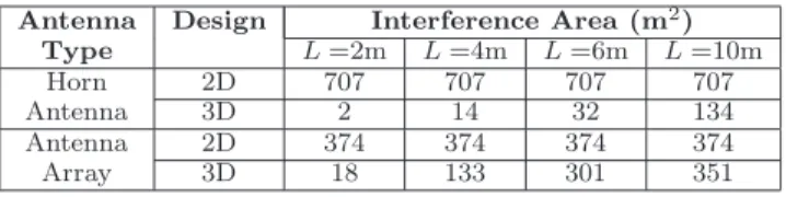
Horn 2D 707 707 707 707
Antenna 3D 2 14 32 134
Antenna 2D 374 374 374 374
Array 3D 18 133 301 351
Table 1: Size of the interference region (interference power>-71 dBm) vs. link lengthL, forh=1m.
compute the link throughput as theuncodedmodulation rate that guarantees a 1% packet error rate (PER) de-fined by the 802.11ad standard [2, 15]. Our result also takes into account the 36% overhead from guard band and pilot [2]. Figure 2(a) shows that 3D beamforming can maintain very high link rates up to 11Gbps3
. Even with a link distance of 50m, it still offers 5.53Gbps.
Furthermore, compared to 2D beamforming, 3D beam-forming achieves similar throughput despite having a longer propagation path (Eq. (1)). This is an artifact of limiting the modulation rate to 256QAM. But even without this restriction, the difference is still<12%.
Reduced Radio Interference. 3D beamforming reduces the interference footprint to the minimum. Fig-ure 2(b)-(c) show the signal energy maps for both 2D and 3D beamforming using today’s horn antenna and antenna array with 10o beam width and the 802.11ad configurations. The sender and receiver are placed at position (0m, 0m) and (2m, 0m) on the map, respec-tively. For 2D beamforming, the directional wave still propagates freely in its beam direction, affecting other receivers along the path. The signal leakage also exac-erbates the level of interference. In contrast, 3D beam-forming bounds the interference region to a much smaller area and limits the impact of signal leakage.
In Table 1, we compare the size of the interference regions of the two beamforming designs while varying the distance between the sender and receiver. We define the interference region as the area whose received inter-ference power is above -71dBm, the noise floor defined by the 802.11ad standard. We see that 3D beamform-ing effectively reduces the interference region for both antenna types. The gain is most significant for shorter links, and for horn antennas due to its smaller signal leakage.
4.
IMPLICATIONS FOR DATA CENTERS
Based on the key properties offered by 3D beamform-ing, we now discuss its short- and long-term implica-tions.
4.1
Immediate Benefits
By extending transmission range while suppressing interference, 3D beamforming allows us to augment ex-isting data center networks with flexible point-to-point
3
The throughput is bounded by 11Gbps because we limit the modulation rate to 256QAM. Without this restriction, rates can go up to 18Gbps.
Rack >1 63 22 3 0
based >2 22 0 0 0
Container >1 83 46 24 8
based >2 56 9 0 0
Table 2: The percentage of transceiver pairs that re-quires multiple hops to connect.
wireless links. We illustrate this benefit by computing the number of concurrent wireless links supported in simulations of two known data center layouts.
• Rack-based: This is the topology used in [15]. Racks are grouped into 4×4 clusters, and each cluster is a row of 10 racks with no inter-spacing. Racks are of 0.6m×1.2m in size and aisles separating the clusters are 3m (between columns) and 2.4m (between rows) wide. In total, the data center is 11m×33m and contains 160 racks.
• Container-based: Offered by Sun Microsystems [5], this data center consists of 2×2 container clusters. Each cluster has 8 containers in a row with an inter-spacing of 0.61m. Each container is of 6.1m×2.4m in size, containing 8 racks laid out in two rows. Container clusters are separated by 3.7m (between columns) and 6.7m (between rows). The entire data center is 15m×50m and contains 256 racks.
We configure wireless links as follows. We assign one radio transceiver per rack and allow each transceiver to associate with one link. We buildbi-directionallinks by randomly selecting transceiver pairs,formingarbitrary rack communication. Each receiver antenna also points to its sender. The maximum number of links for the two topologies are N = 80 and 128, respectively. For each group of N transceiver pairs, we determine the number of concurrent links as follows. We admit links one by one in a random order, compute theircumulative
interference to each other, and only admit a link if all links after admission achieve a minimal rate of 5.53Gbps in the presence of interference. We consider both cases where all the links operate on a single 2.16GHz channel, and cases where three 2.16GHz channels (for the US 60 GHz band) are available.
To examine the impact of link lengths, we bound the distance between each link’s two endpoints by Lmax. Let Dmax represent the maximum separation between two transceivers in each topology, 34.7m and 52.4m, respectively. We varyLmax between [Dmax/10, Dmax]. WhenLmax=Dmax, every pair of transceivers can con-nect in one-hop. WhenLmax< Dmax, some transceiver pairs require multiple hops. Table 2 lists the percentage of transceiver pairs who require more than 1 or 2 hops. Due to space limitations, we only show the results with horn antennas, in terms of the number of concur-rent links (Figure 3(a)-(b)) and the link rate distribu-tion (Figure 3(c)). We make three key observadistribu-tions.
0 10 20 30 40 50 60 70 80 0 5 10 15 20 25 30 35 # of concurrent links Lmax (m) h=2m, 3CH h=3m, 1CH h=2m, 1CH h=1m, 1CH
(a) # of concurrent links, rack-based
0 20 40 60 80 100 120 0 10 20 30 40 50 # of concurrent links Lmax (m) h=2m, 3CH h=3m, 1CH h=2m, 1CH h=1m, 1CH
(b) # of concurrent links, container-based
0 0.1 0.2 0.3 0.4 0.5 0.6 0.7 0.8 0.9 1 5 6 7 8 9 10 11 12 Cumulative distribution
Link data rate (Gbps) container based
rack based
(c) CDF of link data rate
Figure 3: (a) (b) The number of concurrent links supported as a function ofLmax, for the rack-based and container-based topologies, using 1 channel (1CH) or 3 channels (3CH). (c) CDF of link data rate forh= 1mandLmax=Dmax.
Observation 1: 3D beamforming creates wire-like point to point wireless links. Consider the case where Lmax = Dmax thus every transceiver pair connects in 1-hop. Our results show that on average, 30-45 randomly formed links can operate simultaneously on a single channel forh=1-3m. When using three chan-nels, about 75% and 60% links can operate simultane-ously for the two topologies respectively4
. This result shows that we can simultaneously connect the majority of rack pairs wirelessly, using a wire-like connection of rate 5.53+Gbps. Figure 3(c) plots the cumulative dis-tribution of link throughput for this scenario: 50% of links even support data rate higher than 10Gbps!
In total, this adds 0.35-0.4Tbps (1 channel) or 0.54-0.67Tbps (3 channels) of additional flexible bandwidth to the two data centers. We also compare the perfor-mance of 3D and 2D beamforming, assuming there is no link blockage for the latter. We observe a gain of 1.48-2.10. We omit the figure for brevity.
Observation 2: Shorter Links lead to more con-current links. Figure 3(a)-(b) shows that the num-ber of concurrent links increases with a smallerLmax. If we setLmax=Dmax/2, the number of concurrent links supported by three channels increases to 94% and 87% for the two topologies. This is because a smallerLmax increases the receive power, making links more resistant to interference. More importantly, each directed beam arrives at its receiver in a larger elevation angle, pro-ducing a smaller interference region. The only excep-tion is the rack-based topology, where the performance of Lmax = 3.4m is worse than that of Lmax = 6.8m. This is becauseLmax= 3.4mlimits transceiver pairs to those within the same cluster,i.e. a row of racks with no spacing. The dense topology exacerbates the impact of interference.
Observation 3: Increasing ceiling height helps. In Figure 3(a)-(b) we also compare the performance for h=1-3m, where increasing h leads to more concurrent links. This is because a largerhproduces a larger
eleva-4
The number of concurrent links does not grow proportionally with the number of channels because interference patterns are not uniform across links. This negative effect should gradually diminish for increasingly large data centers.
tion angle when directive beams reach their receivers, effectively reducing the interference region. However, the benefit quickly plateaus ath= 3m.
4.2
Long Term Implications
The advantages of 3D beamforming also lead to sev-eral long-term implications for data center networking. Flexible Traffic Scheduling. With the ability to form point-to-point links at multi-Gbps rates, a data center now can schedule jobs with full flexibility, rather than be restricted by configurations defined by physical cables and aggregation routers.
Easy Rack Movement/Replacement. Data cen-ter managers can upgrade or move racks without any physical constraints, and quickly calibrate the beam configuration based on rack locations.
Moving Towards a Full Wireless Data Center. The extended connectivity and reduced interference ad-dress themajor concerns of wireless data centers. This can potentially lead to widespread adoption of wireless links in data centers as replacements for wired cables.
5.
DEPLOYMENT CHALLENGES
In this section, we briefly discuss the key challenges of deploying 3D beamforming in data centers.
Connection Management. Managing 3D beam-forming links faces three challenges. First, to establish a link, two transceivers must choose a mutual data chan-nel and steer their antennas to the right direction. This requires a reliable control path. One can implement the control channel using existing wired connections. A central controller can schedule rack communications by assigning each transceiver pair with their beam direc-tions and channel usage. The second challenge is to assign 60 GHz channels among links to maximize fre-quency reuse. This requires both accurate characteriza-tions of interference condicharacteriza-tions across active links and efficient allocation algorithms. Finally, the mixture of wired and wireless links creates additional challenges in network fault diagnosis and recovery.
Real-time Antenna Rotation. To communicate with different racks, each transceiver must adjust its
tation delay is 50ns [27] for antenna arrays and a few seconds for horn antennae using rotators [3]. Such de-lays must be accounted for in traffic scheduling. Physical Rack/Reflector Placement. 3D beam-forming performs the best when there are no obsta-cles between the top of rack/container and the ceiling. When physically arranging racks/containers as well as ceiling reflectors, data center managers should avoid ob-stacles such as cables and cooling pipes. This is a non-issue for container based data centers, because nothing is placed on top of the containers [5]. For other data centers, raised floors can be used to house cables and pipes in the ground; and data centers using suspended cable trays can conceal them within aluminum-plated ducts, essentially lowering the reflection point from the ceiling. When unavoidable, one can also plan multi-hop transmissions or reflect off walls to route around obstacles. An open question is whether physical rack and reflector placement can be jointly optimized with network communication patterns.
6.
RELATED WORK
Data Center Networks. Most prior work is on ad-dressing traffic congestion via network architecture de-sign and scheduling [6, 8, 9, 12, 13, 14],ormodeling net-work traffic characteristics [10, 11, 16]. Wireless data center was first proposed in [23]. Recent proposals use wireless links to augment [15, 17] or replace [26] wired links. In this work, we identify two practical issues of existing approaches, and propose a new beamforming paradigm to deploy better wireless interconnects. While prior work has applied the principle of reflection to con-nect NLOS links [23] orto reduce WiFi interference [21], we generalize it to 60 GHz links. Our key contribution is to use ceiling reflection in the data center context to extend connectivity and suppress interference.
60 GHz Technology. Prior work on 60 GHz also addressed radio design issues, including modeling prop-agation and reflection characteristics [7, 24, 25, 29] and antenna design [4, 27]. Our work leverages readily avail-able hardware, and focuses on designing new wireless interconnects explicitly for data centers.
7.
CONCLUSION
60 GHz wireless links are an ideal solution to address bursty traffic in the data center. To address link block-age and interference problems in today’s approaches, we propose a 3D beamforming technique that extends the reach of wireless links by avoiding obstacles, while increasing the number of available concurrent transmis-sions by reducing interference. Using two popular data center configurations, we show that a 3D beamforming link can connect any two racks using a single hop, elim-inating the need for multihop wireless links. Finally, we
to augment next generation data center designs.
8.
REFERENCES
[1] Data center managers not fixed on wireless. http://searchdatacenter.techtarget.com/tip/ Data-center-managers-not-fixed-on-wireless. [2] IEEE P802.11ad/D0.1: Enhancements for very high
throughput in the 60 GHz band. Draft 0.1, June 2010. [3] NSI.http://www.nearfield.com/.
[4] SiBeam.http://sibeam.com/whitepapers/. [5] Sun modular datacenter s20/d20 overview.
http://download.oracle.com/docs/cd/E19115-01/mod.dc. s20/index.html.
[6] Abu-Libdeh, H., et al.Symbiotic routing in future data centers. InSIGCOMM (2010).
[7] Ahmadi-Shokouh, J., et al.Reflection coefficient measurement for house flooring materials at 57-64 GHz. In GLOBECOM (2009).
[8] Al-fares, M., et al.Hedera: Dynamic flow scheduling for data center networks. InNSDI (2010).
[9] Al-Fares, M., Loukissas, A., and Vahdat, A.A scalable, commodity data center network architecture. In
SIGCOMM (2008).
[10] Benson, T., et al.Network traffic characteristics of data centers in the wild. InIMC (2010).
[11] Benson, T., et al.Understanding data center traffic characteristics.ACM CCR 40 (2010), 92–99.
[12] Farrington, N., et al.Helios: A hybrid electrical/optical switch architecture for modular data centers. In
SIGCOMM (2010).
[13] Greenberg, A., et al.VL2: A scalable and flexible data center network. InSIGCOMM (2009).
[14] Guo, C., et al.BCube: a high performance, server-centric network architecture for modular data centers. In
SIGCOMM (2009).
[15] Halperin, D., et al.Augmenting data center networks with multi-gigabit wireless links. InSIGCOMM (2011). [16] Kandula, S., et al.The nature of data center traffic:
measurements & analysis. InIMC (2009).
[17] Kandula, S., Padhye, J., and Bahl, V.Flyways to de-congest data center networks. InHotNets (2009). [18] Katayama, Y., et al.Wireless data center networking
with steered-beam mmwave links. InWCNC (2011). [19] Kelleher, K.The Microwave Engineers’ Handbook and
Buyers’ Guide, 5th ed. New York: Horizon Press, 1964. [20] Knop, C., and Wiesenfarth, H.On the radiation from an
open-ended corrugated pipe carrying the HE11 mode.IEEE Trans. on Antennas and Propagation(1972), 644 – 648. [21] Liu, X., et al.DIRC: Increasing indoor wireless capacity
using directional antennas. InSIGCOMM (2009).
[22] Manabe, T., Miura, Y., and Ihara, T.Effects of antenna directivity on indoor multipath propagation characteristics at 60GHz. InPIMRC (1995).
[23] Ranachandran, K., et al.60GHz data-center networking: wireless =>worryless? NEC Technical Report (2008). [24] Sato, K., et al.Measurements of reflection and
transmission characteristics of interior structures of office building in the 60-GHz band.IEEE Trans. on Antennas and Propagation 45, 12 (1997), 1783 –1792.
[25] Sch¨onthier, J.WP3-study “the 60 GHz channel and its modelling”.Tech. Report IST-2001-32686 (2003).
[26] Shin, J.-Y., et al.On the feasibility of completely wireless data centers.Technical Reports, Cornell University(2011). [27] Valdes-garcia, A., et al.Single-element and
phased-array transceiver chipsets for 60-GHz Gb/s communications.IEEE Communications Magazine(2011). [28] Vardhan, H., et al.Wireless data center with millimeter
wave network. InGLOBECOM (2010).
[29] Yong, S.-K., Xia, P., and Valdes-Garcia, A.60 GHz Technology for Gbps WLAN and WPAN: From Theory to Practice. WILEY, 2011.