NFV Management and Orchestration in Large-Scale
Distributed Systems
Mohammad Abu-Lebdeh
A thesis In
The Concordia Institute for
Information Systems Engineering
Presented in Partial Fulfillment of the Requirements For the Degree of
Doctor of Philosophy (Information and Systems Engineering) at Concordia University
Montr´eal, Qu´ebec, Canada
April 2018
c
Concordia University
School of Graduate Studies
This is to certify that the thesis prepared
By: Mohammad Abu-Lebdeh
Entitled: NFV Management and Orchestration in Large-Scale Dis-tributed Systems
and submitted in partial fulfillment of the requirements for the degree of
Doctor of Philosophy (Information and Systems Engineering)
complies with the regulations of this University and meets the accepted standards with respect to originality and quality.
Signed by the final examining committee:
Dr. Ion Stiharu Chair Dr. Jean-Charles Gr´egoire External Examiner Dr. Dongyu Qiu External to Program Dr. Chadi Assi Examiner Dr. Jamal Bentahar Examiner Dr. Roch Glitho Supervisor Approved by
Dr. Chadi Assi, Graduate Program Director
12 June 2018
Dr. Amir Asif, Dean
Abstract
NFV Management and Orchestration in Large-Scale Distributed Systems
Mohammad Abu-Lebdeh, Ph.D. Concordia University, 2018
Network Functions Virtualization (NFV) radically transforms the way network operators design and manage network services, promising a lot of potential benefits such as agility, flexibility, reduction of CAPEX and OPEX. It eliminates the dependency between the net-work function software and hardware enabling pure-software based netnet-work function that runs on commodity hardware, called Virtualized Network Function (VNF). NFV, along with other emerging technologies such as Software-Defined Networking (SDN), enables net-work operators to create dynamic and programmable netnet-work services, wherein VNFs are deployed on-demand, dynamically chained and optimized over time to cope with emerging business needs. The European Telecommunications Standards Institute (ETSI) developed the NFV Management and Orchestration (MANO) framework, which consists of Virtualized Infrastructure Manager (VIM), VNF Manager (VNFM) and NFV Orchestrator (NFVO), in order to provide network operators with the sophisticated capabilities needed to manage the dynamic aspects of infrastructure, VNFs and network services.
This thesis elaborates and addresses key architectural and algorithmic research chal-lenges related to the NFV management and orchestration in distributed and large-scale systems. We look at orchestration scalability from an architectural perspective and pro-pose to leverage two-layer hierarchical service orchestration to manage network services over distributed infrastructure. We also propose an architecture of Virtual Network Platform-as-a-Service (VNPaaS) that utilizes the hierarchical orchestration to offer next-generation mobile networks as-a-service. The architecture is illustrated by offering the 3GPP Home Subscriber Server (HSS) as-a-Service (HSSaaS), in which the HSS is decomposed into VNFs with a granularity finer than what is known today. On the algorithmic side, a key chal-lenge is to identify the number and location of the NFVO and VNFM functional blocks since they have a significant impact on the overall system cost and performance, among others. In particular, we tackle the online placement of VNFM to enable network oper-ators to adjust the number and location of VNFMs in response to variation in workload. There, we assume a fixed location of NFVO and aim at minimizing the operational cost. Owing to its complexity, we propose a tabu search heuristic and numerically show that it is
faster than the mathematical formulation by many orders of magnitude. We further study the joint placement of NFVO and VNFM. We first address the problem in the context of the multi-orchestrator system and seek to minimize the number of NFVOs and VNFMs. We mathematically formulate the problem and propose a two-step placement heuristic to solve the problem efficiently. Finally, we investigate the same problem in the context of single- and multi-orchestrator systems providing a comparative study of the worst-case de-lay in both scenarios. We also propose a late acceptance hill-climbing heuristic to solve the problem in a reasonable time frame.
Acknowledgments
All praise is due to Allah who gave me the strength, determination, patience and guided me throughout this work and beyond.
First, and foremost, I am grateful to my Ph.D. supervisor Prof. Roch Glitho for his guidance, support, patience, and encouragement. He is the dedicated, professional and caring advisor. Thank you.
I gratefully acknowledge my Ph.D. committee members, Prof. Chadi Assi, Prof. Jamal Bentahar and Prof. Dongyu Qiu for their time, effort and constructive comments. I would also like to extend my appreciation to the external examiner Prof. Jean-Charles Gr´egoire for accepting to serve in my Ph.D. thesis committee.
I am also thankful to Dr. Fatna Belqasmi, Dr. Jagruti Sahoo, Dr. Sami Yangui, Dr. Diala Naboulsi and Mr. Constant Wette Tchouati for all the enlightening discussions, comments and collaboration. It was a great pleasure working with you.
Furthermore, I am thankful to all of my colleagues in the telecommunication service en-gineering lab at Concordia University. In particular, I would like to thank Abbas Soltanian, Carla Mouradian, and Narjes-Elaheh Tahghigh for their companionship, support, ideas, and fruitful discussions.
Last but not least, I am forever indebted to my family for their encouragement, contin-uous support, love and prayers. My sincere thanks go to my mother, Aisha. Without you, this thesis would not have been possible. There are no words that can express my gratitude and love for you.
Contents
List of Figures x
List of Tables xiii
List of Acronyms xiv
Chapter 1: Introduction 1
1.1 Overview . . . 1
1.2 NFV Management and Orchestration Framework . . . 3
1.3 Challenges and Thesis Contributions . . . 5
1.3.1 VNF Manager Placement Problem . . . 6
1.3.2 A Scalable Architecture for NFV Management and Orchestration . . 7
1.3.3 Joint Placement of NFV Orchestrator and VNF Manager Problem: The Multi-Orchestrator Case . . . 8
1.3.4 Joint Placement of NFV Orchestrator and VNF Manager Problem: The Single and Multi-Orchestrator Cases . . . 9
1.4 Thesis Outline . . . 9
Chapter 2: Related Work 10 2.1 Requirements . . . 10
2.2 Related Work . . . 11
2.2.1 NFV Management and Orchestration Architecture . . . 11
2.2.2 Resource Allocation . . . 15
Chapter 3: VNF Manager Placement Problem 18 3.1 Introduction . . . 18
3.2 The VNFM Placement Problem . . . 20
3.2.1 Motivation and Problem Statement . . . 20
3.2.3 Problem Formulation . . . 25
3.3 Resolution Approach . . . 30
3.3.1 Initial Solution . . . 31
3.3.2 Neighborhood Structure . . . 33
3.3.3 Tabu List and Aspiration Criterion . . . 34
3.3.4 Acceptance Criterion . . . 34 3.3.5 Termination Criterion . . . 35 3.4 Evaluation Scenarios . . . 35 3.4.1 Simulation Setup . . . 35 3.4.2 Static MPP Experiments . . . 38 3.4.3 Dynamic MPP Experiments . . . 38 3.5 Numerical Results . . . 39
3.5.1 Heuristic Performance Evaluation . . . 40
3.5.2 Optimization Objective Weight . . . 45
3.5.3 Impact of NFVO Location . . . 46
3.5.4 Architectural Options Related to VNFM . . . 46
3.5.5 Large-Scale Deployment . . . 52
3.5.6 Dynamic Placement Evaluation . . . 52
3.6 Conclusion . . . 54
Chapter 4: A Scalable Architecture for NFV Management and Orches-tration 55 4.1 Introduction . . . 55
4.2 4G Mobile System Architecture: Overview and Challenges . . . 56
4.2.1 Challenges for Mobile Network Cloudification . . . 59
4.3 VNPaaS Architecture . . . 60
4.3.1 Business Model . . . 60
4.3.2 Layers and Functional Components . . . 61
4.3.3 Operational Procedures . . . 64
4.4 Illustrative Use Case: HSS-as-a-Service . . . 65
4.4.1 NFV-based HSS . . . 65 4.4.2 Illustrative Scenario . . . 66 4.5 Prototype Implementation . . . 68 4.5.1 VNPaaS . . . 68 4.5.2 HSSaaS . . . 70 4.6 Performance Evaluation . . . 70
4.6.1 Response Time . . . 71
4.6.2 Resource Usage . . . 74
4.7 Conclusion . . . 76
Chapter 5: Joint Placement of NFV Orchestrator and VNF Manager: The Multi-Orchestrator Case 77 5.1 Introduction . . . 77
5.2 The Joint Placement of NFVO and VNFO . . . 78
5.2.1 System Model . . . 79
5.2.2 Problem Formulation . . . 81
5.3 Two-Step Placement Heuristic . . . 84
5.3.1 NFVO Placement . . . 85
5.4 Evaluation . . . 86
5.4.1 Simulation Setup . . . 87
5.4.2 Numerical Results . . . 87
5.5 Conclusion . . . 89
Chapter 6: Joint Placement of NFV Orchestrator and VNF Manager: The Single and Multi-Orchestrator Cases 90 6.1 Introduction . . . 90
6.2 The NFVO and VNFM Placement Problem . . . 91
6.2.1 The Single-Orchestrator Case . . . 92
6.2.2 The Multi-Orchestrator Case . . . 97
6.3 Proposed Heuristic . . . 100
6.3.1 Late Acceptance Hill-Climbing . . . 101
6.3.2 Parallelization Approach . . . 104
6.4 Numerical Results . . . 105
6.4.1 Simulation Setup . . . 106
6.4.2 Impact of Number of NFVOs . . . 107
6.4.3 Impact of Number of VNFMs . . . 108
6.4.4 Heuristic Performance . . . 110
6.5 Conclusion . . . 113
Chapter 7: Conclusion and Future work 114 7.1 Future Work . . . 116
7.1.1 Distributed NFV Infrastructure Design . . . 116
7.1.3 Resilience of NFV Management and Orchestration . . . 116
List of Figures
1.1 ETSI NFV architectural framework [6] . . . 3
3.1 ETSI NFV MANO framework [7] . . . 21
3.2 Illustration of the motivation for the VNFM placement problem . . . 22
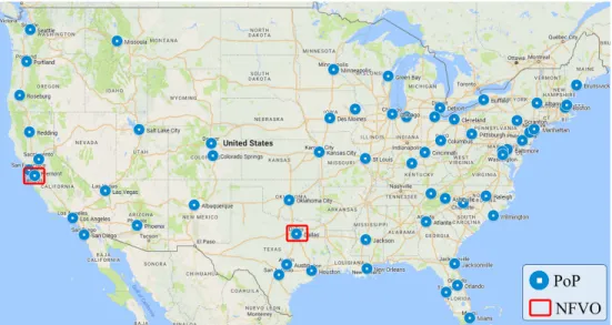
3.3 64 PoPs distributed across the USA . . . 39
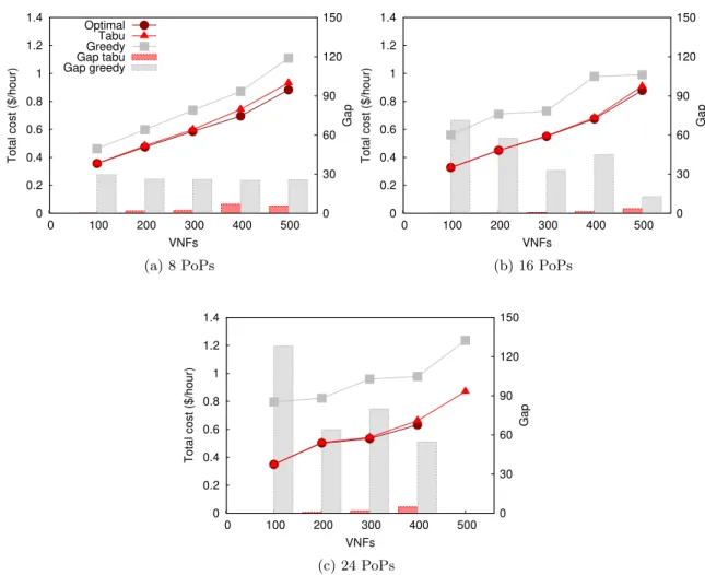
3.4 Total cost for optimal, tabu and greedy solutions, together with the gap from optimality for the tabu and greedy heuristics with ε = 1. The results are derived by assuming the NFVO is located in Dallas . . . 41
3.5 Total cost for optimal, tabu and greedy solutions, together with the gap from optimality for the tabu and greedy heuristics with ε = 20. The results are derived by assuming the NFVO is located in Dallas . . . 42
3.6 Total cost for optimal, tabu and greedy solutions, together with the gap from optimality for the tabu and greedy heuristics with ε = 1. The results are derived by assuming the NFVO is located in San Jose . . . 43
3.7 Total cost for optimal, tabu and greedy solutions, together with the gap from optimality for the tabu and greedy heuristics with ε = 20. The results are derived by assuming the NFVO is located in San Jose . . . 44
3.8 Number of VNFMs placed in the system with respect to the number VNF instances with ε= 1 and ε= 20 . . . 47
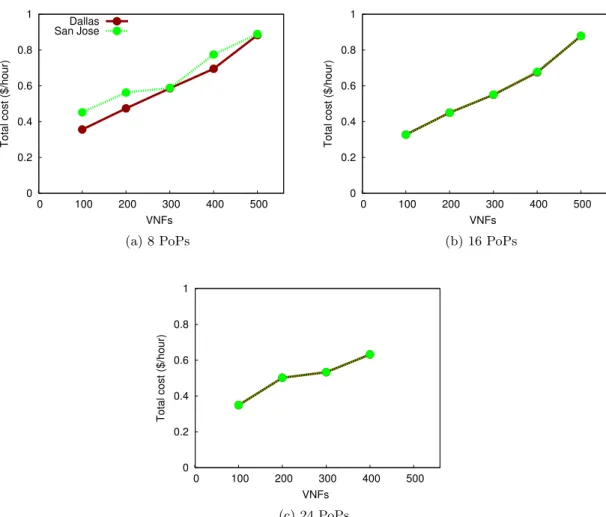
3.9 Total cost for optimal solutions with ε= 1 for the NFVO placed in Dallas and NFVO placed in San Jose . . . 48
3.10 Total cost for optimal solutions with ε= 20 for the NFVO placed in Dallas and NFVO placed in San Jose . . . 49
3.11 Total cost for optimal and tabu solutions withε= 1 for the VNFM architec-tural options: generic and VNF-specific. The results are derived by assuming the NFVO is located in Dallas. . . 50
3.12 Total cost for optimal and tabu solutions with ε = 20 for the VNFM ar-chitectural options: generic and VNF-specific. The results are derived by
assuming the NFVO is located in Dallas . . . 51
3.13 Total cost for tabu and greedy solutions in large-scale deployments. The results are derived by assuming the NFVO is located in Dallas . . . 52
3.14 Total cost for tabu solutions in large-scale deployments for the NFVO placed in Dallas and NFVO placed in San Jose . . . 53
3.15 Total cost for optimal and tabu solutions of the dynamic MPP and for optimal solution of the static MPP . . . 53
4.1 Simplified EPS architecture . . . 57
4.2 VNPaaS high-level architecture . . . 61
4.3 Two-layer hierarchical service orchestration . . . 62
4.4 High-level TOSCA topology templates . . . 66
4.5 Illustrative HSSaaS deployment scenario . . . 67
4.6 VNPaaS Prototype architecture . . . 69
4.7 Response time CDF obtained when aggregating all samples for each experiment 72 4.8 Response time CDF of all samples over the S6a and Cx interfaces, for R = 90% experiments . . . 73
4.9 Response time distribution per message type (e), for one split (S) and one full (F) HSS-FE experiments with R = 90% . . . 74
4.10 Number of deployed containers . . . 76
5.1 High-level system architecture . . . 78
5.2 Objective function value . . . 88
5.3 Number of NFVOs . . . 88
5.4 Number of VNFMs . . . 89
6.1 System model . . . 92
6.2 Single-orchestrator system architecture . . . 94
6.3 Multi-orchestrator system architecture . . . 97
6.4 Worst-case delay between NFVO and VIM . . . 108
6.5 A comparison of worst-case delay between NFVO and VIM, and between VNFM and VNF . . . 108
6.6 Worst-case delay between VNFM and VNF functional blocks. The results are derived with γ = 4 and two NFVOs in the multi-orchestrator case . . . 109
6.7 Worst-case delay between NFVO and VNFM . . . 109
6.8 Objective function value for AT&T topology in single-orchestrator case . . 111
6.10 Objective function value for AT&T topology in multi-orchestrator case . . . 112 6.11 Objective function value for CDN77 topology in multi-orchestrator case . . 112
List of Tables
3.1 Notations Description . . . 26
3.2 Experiment Parameters . . . 37
3.3 Average Execution Time . . . 45
4.1 Diameter Traffic Details . . . 71
4.2 Number of Diameter Messages . . . 72
4.3 HSS-FE Scaling Policies . . . 75
5.1 Summary of Key Notations . . . 80
5.2 Simulation Parameters . . . 86
6.1 Summary of Key Notations . . . 93
List of Acronyms
3GPP 3rd Generation Partnership ProjectAIR Authentication Information Request API Application Programming Interface
CDF Cumulative Distribution Function CDN Content Delivery Network
CSCF Call State Control Function
EM Element Management EPC Evolved Packet Core
ePDG evolved Packet Data Gateway EPS Evolved Packet System
ETSI European Telecommunications Standards Institute
FCAPS Fault, Configuration, Accounting, Performance, and Security
FE Front End
FLP Facility Location Problem
GSO Global Service Orchestrator
HSS Home Subscriber Server
HSS-FE Home Subscriber Server Front End HSSaaS Home Subscriber Server as-a-Service
I-CSCF Interrogating Call State Control Function ILP Integer Linear Programming
IMS IP Multimedia Subsystem ISG Industry Specification Group
KPI Key Performance Indicator
LAHC Late Acceptance Hill-Climbing LIR Location Info Request
LTE Long Term Evolution
MANO Management and Orchestration MAR Multimedia Authentication Request MME Mobility Management Entity MPP VNFM Placement Problem MVNO Mobile Virtual Network Operator
NFaaS Network Functions-as-a-Service NFV Network Function Virtualization
NFVI Network Function Virtualization Infrastructure NFVIaaS NFVI-as-a-Service
NFVO Network Function Virtualization Orchestrator
OMP-MO NFVO and VNFM Placement in Multi-Domain OMP-SO NFVO and VNFM Placement in Single-Domain ONAP Open Network Automation Platform
P-CSCF Proxy Call State Control Function PaaS Platform-as-a-Service
PCC Policy and Charging Control PCRF Policy and Charging Rule Function PDN-GW Packet Data Network Gateway PoP Points of Presence
S-CSCF Serving Call State Control Function S-GW Serving Gateway
SAR Server Assignment Request SDN Software-Defined Networking SIP Session Initiation Protocol
SIP-AS Session Initiation Protocol-Application Server SPR Subscription Profile Repository
TOSCA Topology and Orchestration Specification for Cloud Applications TSP Two-Step Placement
UAR User Authorization Request UDC User Data Convergence UDR User Data Repository UE User Equipment
ULR Update Location Request
vCPE virtual Customer Premises Equipment VM Virtual Machine
VNaaS Virtual Network-as-a-Service VNF Virtualized Network Function VNFaaS VNF-as-a-Service
VNFM Virtualized Network Function Manager VNPaaS Virtual Network Platform-as-a-Service
Chapter 1
Introduction
1.1
Overview
During the past decade, cloud computing has gained significant momentum for delivering computing resources (e.g., networks, servers and storage) as utility [1]. These resources are pooled, generally using virtualization technologies, and offered to different users (in-dividuals and enterprises), who can dynamically provision and release these resources to accommodate their demand following the pay-as-you-go financial model. Cloud computing replaces up-front resource provisioning with elastic resource allocation, which stimulates the emergence of sophisticated cloud automation tools that accelerate innovation through auto-mated provisioning, governance, and management of the cloud services, enabling enterprises to provide agile, scalable and cost-efficient cloud services.
The success of cloud computing, as an approach for providing scalable and cost-efficient services, motived leading telecommunication network operators to initiate an Industry Spec-ification Group (ISG), within the European Telecommunications Standards Institute (ETSI) to overcome current network deficiencies by leveraging cloud technologies (e.g., virtual-ization and automation) [2]. Today, introducing new network services often requires the deployment of additional proprietary hardware appliances at fixed locations in the infras-tructure. These appliances are designed to perform particular network functions and cannot be easily modified to support new operations. This static approach in service management
limits the capability of innovation and support for new services. It also leads to low resource utilization, high capital and operational expenditures [3].
ETSI proposed the notion of Network Functions Virtualization (NFV) to enable net-work functions to run as cloud applications and allow netnet-work services to be provisioned as cloud services [2]. NFV [4] eliminates the dependency between the network function software and underlying hardware and implements the network function in software module called Virtualized Network Function (VNF), which enables consolidation of many network equipment onto standard high volume servers, switches and storage. By that, NFV, along with other emerging technologies such as Software-Defined Networking (SDN), enables net-work operators to create dynamic and programmable netnet-work services, wherein VNFs are deployed on-demand at any point in the infrastructure, dynamically linked and optimized over time to cope with emerging business cases and needs [5].
Currently, ETSI is leading the way in the standardization of NFV. So far, it has de-veloped a set of requirements, specifications and architectures that cover various aspects of NFV technology. Among them is the NFV architectural framework [6] depicted in Fig-ure 1.1. It describes the building blocks of an NFV system in an administrative domain. It encompasses VNFs, NFV Infrastructure (NFVI) and NFV Management and Orchestra-tion (MANO) framework. VNFs are the software implementaOrchestra-tion of the network funcOrchestra-tions. NFVI is the environment in which VNFs are deployed. It is a combination of hardware and software resources that may span several geographically distributed locations. A single location, where a network function could be deployed as VNF, is called a Point of Pres-ence (PoP). Moreover, the MANO framework [7] is responsible for the orchestration and lifecycle management of network services including all relevant functions, such as deploying VNFs, optimizing their performance and managing their associated resources. Currently, it is the most prominent NFV management framework and has been adopted by a majority of open-source and commercial NFV platforms [8,9]. The next section sheds more light on this framework.
Figure 1.1: ETSI NFV architectural framework [6]
1.2
NFV Management and Orchestration Framework
The ETSI NFV MANO framework consists of three functional blocks: the Virtualized Infrastructure Manager (VIM), the VNF Manager (VNFM) and the NFV Orchestrator (NFVO). These functional blocks form three distinct management layers with different functional roles as explained next:
1. VIM: The VIM manages and controls the NFVI compute, storage and network re-sources. For example, it performs resource allocation and de-allocation on behalf of the NFVO and VNFM. It also collects and reports resource fault and performance information. The NFVI resources can be managed by one or more of VIMs. Each VIM can manage a subset of resources within a PoP, all resources within a PoP, or the resources across multiple PoPs [7].
2. VNFM: The VNFM is responsible for the lifecycle management of one or more VNF instances. As such, each VNF instance is associated with a VNFM. Lifecycle management refers to the set of functions required to manage the instantiation, maintenance and termi-nation of a VNF or network service [10]. In this context, for instance, the VNFM can collect the virtualized resource performance information from the VIM, and the VNF indicators
from the Element Management (EM) or VNF instance. An indicator is application-level information that provides insight into the VNF behavior [11]. The VNFM uses the collected information for decision making, such as VNF scaling and healing. Furthermore, the VNFM can be either generic or VNF-specific [12]. A generic VNFM can manage VNF instances of different types that might be provided by different VNF providers. A VNF-specific VNFM has a dependency on the VNFs and can manage VNF instances of defined type(s), usually provided by the VNF provider [12]. In an administrative domain, one or more VNFMs can be used to manage the VNF instances. Further, as shown in Figure 1.1, the VNFM may communicate with Element Management (EM) to manage the VNF instances. EM is responsible for FCAPS (Fault, Configuration, Accounting, Performance, and Security) management functionality for one or more of VNF instances. It has overlapping functions with the VNFM. However, the key difference between them is that the EM manages a VNF instance through a proprietary reference point, whereas the VNFM uses a standard reference point [13]. By that, the EM can play the role of proxy by exposing the VNF management functions to the VNFM through a standard reference point [13].
3. NFVO: Two main tasks are delegated to the NFVO. First, it performs resource orchestration across multiple VIMs. The role of NFVO involves, but not limited to, resource request authorization and capacity management. Second, it is in charge of the lifecycle management of network services which involves coordination with VNFMs in managing the lifecycle of VNF instances. For example, the NFVO and VNFMs work jointly to ensure that the VNF instances meet the desired requirements (e.g., performance). The NFVO can collect the VNF indicators and virtualized resource performance metrics from VNFMs. It analyzes this information to assure that the network services satisfy their requirements. Finally, it is worth noting that a single NFVO exists in an administrative domain.
Moreover, the NFV MANO framework includes a set of reference points, as shown in Figure 1.1, to enable communications among MANO functional blocks as well as the com-munication with other NFV functional blocks such as EM and VNF. ETSI specifications [11,
points. However, the details of the operations and the communication protocols are not discussed. We highlight in particular, the following reference points that are relevant to our work: Or-Vnfm, a reference point between the NFVO and VNFM; Or-Vi, a reference point between the NFVO and VIM; Vi-Vnfm, a reference point between VNFM and VIM;
Ve-Vnfm, a reference point between VNFM and EM/VNF instance.
1.3
Challenges and Thesis Contributions
The responsibilities associated with MANO functional blocks leave no doubt that their performance is crucial to network operators. Today, there are many emerging NFV scenarios where the network services will span large geographical area (e.g., country or continent) and the number of VNF instances will grow tremendously. For instance, the forthcoming 5G cellular system, for which NFV is considered an essential enabling technology [18, 19], is likely to run on a highly distributed NFVI to satisfy the requirement of 1 ms round-trip latency. 5G also requires scalable NFV architecture to deliver the required massive capacity and connectivity [20]. Another example is the Content Delivery Network (CDN) which is typically deployed over a large geographical area to deliver contents (e.g., video) to end-users with low delay. In these scenarios, the distributed nature and scale of NFV deployments lead to scalability and performance issues:
• Communication delay: The decision making in NFV MANO framework is distributed among the three functional blocks (i.e., VIM, VNFM and NFVO). These functional blocks communicate with each other and with other NFV functional blocks (e.g., VNFs) in order to fulfill their functionalities. The physical distance between the functional blocks in NFV system is one of the factors that introduce communication delay. When the communication delay is high, the execution time of the MANO oper-ations becomes longer which decreases the scalability and degrades the performance. According to [8], the communication overhead and delay may prevent the frequent collection and analysis of monitoring data (e.g., performance information) from the environment (e.g., VNF instances and VIMs). Another example is the VNF fault
management [21]. Fast failure notification and recovery are necessary to minimize the impact of the failure and maintain the reliability of the network services.
• Centralized MANO: Relying on single NFVO in a distributed and large-scale de-ployment will hinder the scalability of the orchestration process [22]. As the NFV deployment grows with respect to the infrastructure size and the number of VNFs, the NFVO will have to cope with more requests and events. Since the system is bounded by the processing capacity of the NFVO, it can become a bottleneck as the load grows with the size of the deployment. Besides, if the NFVI has a large diame-ter, no matter where the NFVO is placed, the communication with other functional blocks, especially VIM, would encounter a high delay.
• Number of VNFMs: The VNFM functional block is responsible for the lifecycle man-agement of VNF instances. However, in large-scale deployments, the VNFMs should manage thousands of VNF instances without compromising the performance of its management functions. Thus, the number of VNFMs must be adequate to cope with the number of VNF instances.
These obstacles must be addressed before NFV can advance to reality, especially when the network services in production deployments are associated with carrier-grade require-ments. This thesis aims to supplement the undergoing research efforts towards design and operate NFV MANO platforms. The thesis addresses fundamental architectural and re-source allocation challenges related to the NFV MANO. These problems are summarized next.
1.3.1 VNF Manager Placement Problem
As defined by the NFV MANO framework, the VNFM functional block is responsible for the lifecycle management of the VNFs. However, these VNFs can be instantiated on-demand when and where needed and elastically scaled to meet the on-demand variability while maintaining cost efficiency. Hence, the number of VNF instances, their types (e.g., firewall) and locations can vary over time. The VNFMs should manage the lifecycle of thousands
of VNF instances without compromising the performance of its management functions. At any time, the number of VNFMs should be adapted to the VNF instances deployed in the system, for optimal performance of the system. Besides, the placement of VNFM can significantly affect the overall system performance and operational cost. Adapting the number and placement of VNFMs accordingly can thus result in important savings for operators.
In this thesis, we introduce and investigate the VNFM Placement Problem (MPP). We present two versions of the problem: static MPP with permanent placement decisions and dynamic MPP with placement decisions that change over time. Assuming that we are given the placement of the NFVO, the dynamic placement configuration of a set of VNF instances over geographically distributed NFVI, we aim at finding the optimal number and placement of the VNFMs, at each moment, that minimizes the operational cost. We mathematically formulate the VNFM placement problem and propose a tabu search metaheuristic to solve large instances of the problem. We compare our tabu approach against the mathematical model over various NFVI topologies. Our numerical results show that our tabu search heuristic yields high-quality solutions in considerably fast runtime. Moreover, we study the impact of crucial aspects, i.e., NFVO location, VNFM architectural options (generic and VNF-specific) on the outcome of the problem. We show that they can have a notable impact on the placement decisions and require adequate tuning according to the operators’ requirements.
1.3.2 A Scalable Architecture for NFV Management and Orchestration
Centralized NFV MANO solutions, which were the common approach in literature until recently, are prone to scalability and performance issues in large-scale and distributed de-ployments [8,22]. These solutions rely on a single NFVO in the system which would hinder the scalability of the orchestration process [22]. On the one hand, the number of network services and their constitute VNFs would grow far beyond the processing capacity of an NFVO. On the other hand, the delay between the NFVO and other functional blocks would increase with the increase of the size of the covered geographical area. A high network delay
increases the communication overhead and can negatively impact critical functions. In this thesis, we propose to employ two-layer hierarchical service orchestration in order to address these challenges, wherein the NFVI is decomposed into domains (or orchestration zones) and an NFVO is assigned the resource and service orchestration within a domain. By that, NFVO can be placed close to hosting infrastructure and the communication overhead is minimized. Besides, a global service orchestrator performs the end-to-end service or-chestrations across different domains. We propose an architecture of Platform-as-a-Service, which utilizes the two-layer hierarchical service orchestration approach, for provisioning 3GPP 4G and beyond core networks as-a-service. We also present a proof-of-concept proto-type to validate the feasibility of the approach. We use the Home Subscriber Server (HSS) as-a-Service (HSSaaS) as an illustrative use case. It relies on a novel NFV-based architec-ture of HSS, in which the HSS is decomposed into VNFs with a granularity finer than what is known today. The new architecture allows the different diameter interfaces of HSS to be deployed and scaled independently. It also enables performance isolation between these interfaces, which is further demonstrated by experimentation.
1.3.3 Joint Placement of NFV Orchestrator and VNF Manager Problem: The Multi-Orchestrator Case
As mentioned earlier, we propose multi-orchestrator and hierarchical orchestration archi-tecture to address the NFV MANO scalability and performance challenges for large-scale and distributed NFV systems, wherein multiple instances of NFVO and VNFM are used to manage the lifecycle of network services and VNFs. However, there is still the challenge of finding the optimal number and placement for these functions blocks that provide the required capacity and performance. Hence, we introduce and study the joint placement of NFVO and VNFM in the context of the multi-orchestrator system. In particular, given the NFVI topology, a set of VNF instances, and the location of the global service orchestrator, we aim at finding the number and placement of NFVOs and VNFMs needed in the system that minimizes their number, as it is a measure of the cost. We mathematically formulate the problem, propose a two-step placement heuristic and evaluate it.
1.3.4 Joint Placement of NFV Orchestrator and VNF Manager Problem: The Single and Multi-Orchestrator Cases
Since the locations of NFVO and VNFM functional blocks have a significant impact on the delay experienced in the communication, we revisit the joint placement of NFVO and VNFM problem aiming at minimizing the total worst-case delay between the various functional blocks for both single- and multi-orchestrator systems. We also investigate the impact of the number of NFVOs and VNFMs on the worst-case delay providing a comparative study of the delay in both scenarios. Moreover, we present mathematical formulations of both problems and propose a late acceptance hill-climbing heuristic to solve them in a reasonable time frame.
1.4
Thesis Outline
The rest of the thesis is organized as follows. Chapter 2 presents the requirements of the NFV MANO related to our work, followed by a thorough review of the state-of-the-art. Chapter 3 discusses the VNFM placement problem. In chapter 4, we propose a scalable architecture for NFV management and orchestration. Chapter 5 discusses the joint place-ment of NFVO and VNFM functional blocks for the multi-orchestrator system. We revisit the placement of NFVO and VNFM problem in chapter 6 and investigate the problem for both single- and multi-orchestrator systems. We conclude this manuscript in chapter 7 and provide future directions for this research.
Chapter 2
Related Work
In this chapter, we first present the requirements of the NFV MANO related to our work. After that, in the light of these requirements, we survey the state-of-the-art and review it.
2.1
Requirements
We consider the following requirements to be the most pertinent to NFV MANO:
1. Scalability: NFV MANO functions are important for realizing network services asso-ciated with the carrier-grade characteristics. The NFV MANO platforms should be scalable to exploit the benefits of NFV, given that the design aspects of NFV MANO such as workload and propagation delay among functional blocks can lead to long response time, affecting the ability to respond rapidly to events and reducing the re-liability of the system. Addressing such a problem requires a solution with a scalable architecture. Besides, both the number and location of NFVO and VNFM functional blocks must be planned to provide the needed scalability and performance.
2. Elasticity: VNFs can be deployed and scaled dynamically to meet demand. This will lead to workload fluctuation on the NFVO and VNFM functional blocks. Depending on the level of variation, adding new instances of these functional blocks or removing existing ones might be necessary to cope with the workload and ensure cost-efficiency.
This is, in particular, more relevant to the VNFM as it is responsible for VNF lifecycle management.
2.2
Related Work
In this section, we will discuss the works from the literature that are closely related to each of the thesis contributions. We first discuss and analyze the works related to the NFV MANO architecture. After that, we review the works related to the resource allocation for NFV MANO functional blocks.
2.2.1 NFV Management and Orchestration Architecture
The NFV community has paid particular attention to NFV MANO challenges and designed platforms that can provision network services over distributed infrastructure. We classify these solutions into two categories based on whether they follow the centralized or dis-tributed management approach. We consider the management is centralized when a single NFVO is in charge of resource and service orchestration in the system. On the other hand, the management is distributed when the architecture employs multiple NFVOs to perform the MANO operations (i.e., multi-orchestrator system).
2.2.1.1 Centralized Approach
T-NOVA [23,24] is a European funded project that designs and implements an NFV man-agement and orchestration platform for provisioning network functions-as-a-service over a distributed infrastructure. It provides a VNF marketplace for third-party which allows VNF developers to describe and publish service offerings. It also enables customers to browse, select and deploy these services. The proposed solution covers the entire ETSI NFV MANO framework stack (i.e., VIM, VNFM and NFVO). It encompasses an orchestra-tor called TeNOR that provides ETSI NFVO and VNFM functionalities and can automate four phases of the network service lifecycle management, namely: resource discovery, ser-vice mapping, serser-vice deployment and monitoring. SONATA [25] is another European
project that provides network services development and orchestration functionalities. The proposed architecture consists of two main components: a software development kit and a service orchestration platform. The software development kit allows developers to de-fine complex services consisting of multiple VNFs that can be deployed and managed on SONATA service platform. SONATA service platform provides a customizable management and orchestration framework.
Moreover, Sciancalepore et al. [26] study the impact of co-existence of multi-access edge computing applications and VNFs on the same infrastructure in the context of 5G sys-tems. The authors propose an extension to the ETSI NFV MANO framework in order to enable the join orchestration of VNFs and multi-access edge computing applications and consequently reduce the infrastructure and operational cost. Garcia et al. [27] propose a platform-as-a-service architecture to enable deployment and provisioning of real-time mul-timedia communications and media processing services in an NFV environment. The pro-posed architecture encompasses NFVO and VNFM functional blocks in order to support lifecycle management of media servers and cloud repository. Vilalta et al. [28] propose an architecture to manage network services over for multi-domain transport networks and distributed NFVI. The architecture is illustrated through two use cases: virtual path com-putation element and virtual SDN controllers.
Furthermore, there are several open-source projects that aim to provide reference im-plementations of the ETSI NFV MANO framework. For instance, Tacker [29] emerged as an OpenStack project to provide the functionalities of NFVO and generic VNFM to deploy and operate VNFs. OpenMANO [30] is an ETSI hosted project that aims to build man-agement and orchestration stack aligned with ETSI NFV specifications. OpenBaton [31] is another example which provides an NFV orchestration solution that supports NFVO, generic VNFM and generic EM capabilities to enable VNF deployment on the top of mul-tiple cloud infrastructure.
All presented MANO solutions follow the same approach and try to build an NFV plat-form with centralized management. As discussed earlier, this approach leads to scalability and performance issues as the NFVO would become a potential bottleneck in the system. In
addition, the design and operational aspects of NFV MANO, such as number and placement of MANO functional blocks, are not discussed.
2.2.1.2 Distributed Approach
Recently, several studies have embraced distributed MANO approach in order to address various orchestration challenges such as multi-technology and multi-administrative domains orchestration. In these architectures, multiple orchestrators collaborate in performing the resource and network service orchestration in the system. Each orchestrator performs the orchestration functions over part of the infrastructure, often referred to as a domain. The orchestrators coordinate with each other to ensure the delivery of end-to-end network ser-vice. However, since there is no standard architecture to define the interactions among these orchestrators, several design choices have emerged in the literature. Broadly speaking, these approaches can be classified into three models, namely: hierarchical, flat (or peer-to-peer) and hybrid models.
The hierarchical model organizes the orchestrators into two or more layers. The or-chestrators in the bottom layer perform resource and service orchestration within their domains. Meanwhile, the orchestrators in the second layer and upwards are responsible for the service orchestration across multiple orchestrators in the lower adjacent layer. The top layer often encompasses a global service orchestrator that maintains a global view of the entire system and is in charge of end-to-end service orchestration. This model relies on vertical communications between the orchestrators in adjacent layers. In contrast, the flat model does not exercise hierarchical control among orchestrators. It is, in fact, adopts hor-izontal communications and allows individual orchestrators to communicate directly with other orchestrators. Moreover, the hybrid model is a composition of the hierarchical and flat models. It organizes the orchestrators into layers with vertical communications between ad-jacent layers. Nevertheless, it allows horizontal communications between the orchestrators in the same layer.
The majority of the works available in the state-of-the-art adopted hierarchical orches-tration. For instance, Garay et al. [22] propose a novel service graph model that can be
split into subgraphs according to the orchestrator responsible for the assigned resources and consequently it enables hierarchical orchestration of network services. Further, an ETSI report [15] presents two-layer hierarchical service orchestration as an architectural option emerged due to the design flexibility of ETSI NFV MANO framework. The archi-tecture aims to address the challenge of providing end-to-end network services across two administrative domains. There, the architecture encompasses two layers of orchestrators. In the bottom layer, there is an NFVO in each domain that performs resource and network service orchestration within its domain. The top layer includes an umbrella NFVO that is responsible for the orchestration of network services across the two domains.
Two-layer hierarchical service orchestration has also been applied by [32,33]. Katsalis et al. [32] focus on multi-domain orchestration over multi-technology domains. Open Network Automation Platform (ONAP) [33] is an open source platform that is derived from AT&T’s OpenECOMP and Open-O projects. It provides policy-driven orchestration and automa-tion of physical and virtual network funcautoma-tions. The ONAP Amsterdam release supports hierarchical service orchestration wherein the service orchestrator component is in charge of end-to-end service orchestration and virtual function controller component, which provides ETSI NFV compliant NFVO functions, is responsible for lifecycle management of network services [34].
Further, Li et al. [35] propose a 5G cross-haul architecture that encompasses three network segments: access, cross-haul and core networks. Each of the segments has its dedicated MANO functional blocks, i.e., NFVO, VNFM and VIM. The authors claim that both hierarchical and flat models are applicable to provide end-to-end network services across all segments. Besides, the European 5G Exchange (5GEx) project [36] proposes a platform to enable service orchestration over multiple domains for the same or different administrations in the context of 5G. The platform supports hybrid orchestration model.
In all above-discussed studies, the NFV MANO scalability challenge has been discussed only in [22]. However, the study does not include an architecture realizing the idea; rather, it stays at the conceptual level. The design aspects of NFV MANO are out of the scope of the remaining works, which aim at addressing other challenges such as orchestration of
multi-technology and multi-administrative domains.
2.2.2 Resource Allocation
To the best of our knowledge, there are no previous studies that discuss and target the placement of NFVO MANO functional blocks. We thus review the works that have been done on similar problems in the area of NFV and SDN, in particular, the VNF placement and SDN controller placement problems.
2.2.2.1 VNF Placement
The problem of placing chains of VNF instances has been extensively studied [37]. There, the idea is to optimize the placement of chains of VNF instances, over commodity servers in the system, by reserving resources as needed and according to a predefined objective. A chain of VNF instances is a sequence of VNF instances that together offer a network service. A variety of objectives has been covered in the literature. Kim et al. [38] propose VNF placement strategy that seeks to minimize the overall energy consumption while guar-anteeing the service latency requested by end-users. Bhamare et al. [39] aim at minimizing inter-cloud traffic and response time over geographically distributed clouds. Cao et al. [40] investigate the VNF placement for 5G mobile networks in order to achieve lower bandwidth consumption and lower maximum link utilization. Pham et al. [41] propose a placement strategy that minimizes energy and traffic cost. Moens et al. [42] focus on minimizing the number of used nodes. Mechtri et al. [43] aim at enabling efficient resource utilization in the system. The objective targeted by Hirwe et al. [44] is instead to minimize the length of paths traversed by flows. Qu et al. [45] and Xia et al. [46] target the minimization of communication cost. Minimizing the global operational cost, covering setup and network traffic costs, has been the focus of several works including Ghaznavi et al. [47], Cohen et al. [48] and Bouet et al. [49]. Mehraghdam et al. [50] push the analysis even further and study trade-offs among different optimization objectives including maximizing the data rate, minimizing the number of used nodes and minimizing the delay.
community, the resource allocation for NFV MANO has not received any attention so far. The resource allocation for NFV MANO differs from the VNF placement problem and needs to be studied per se. In fact, different functional blocks are implied in each of them. As per definition, the VNF placement problem implies solely the VNF instances [37], aiming at serving requests, and disregards NFV MANO functional blocks. Instead, in the resource allocation for NFV MANO, various functional blocks are involved. These include the placed VNF instances, EMs, VIMs, VNFMs and the NFVO.
2.2.2.2 SDN Controller Placement
Similar to our problems in the area of SDN is the controller placement problem. The problem can be stated as selecting the location of one or more SDN controllers and allocating switches to these controllers to optimize a certain objective [51]. The problem has been introduced by Heller et al. [52] who showed that random placement of a controller might yield a solution with five times worse latency than an optimal one. The problem has gained significant attention over the past few years in the networking community as it impacts different aspects of SDN networks like performance, cost, and resiliency. The proposed placement strategies in the literature can be classified into a static approach and a dynamic approach. The static problem corresponds to a static network design problem which uses static mapping of switches to controllers. The dynamic placement dynamically adapts the number of controllers and their locations with changing network conditions. Different metrics have been considered to find the number and location of the controller(s). According to Huque et al. [53], the placement strategies can be classified into two categories depending on the used metrics. The first category uses only the latency between switches and controllers to identify the number and locations of controllers in the network. The second category considers the latency and traffic load of switches to find the number and location of controllers.
A variety of objectives has been targeted in literature. For example, Killi et al. [54] propose a placement strategy that plans for controller failures and assigns every switch to more than one controller to ensure reliability; one controller serves as a primary controller
while the others are backup. The proposed strategy aims to minimize the maximum sum of the latency from the switch to the closest controller with enough capacity (primary con-troller) and the latency from the primary controller to its closest controller with enough capacity (backup controller). Bari et al. [55] consider the dynamic controller placement problem where the number and location of controllers are adjusted according to network dynamics. The authors propose a management framework for dynamically deploying mul-tiple controllers within a Wide Area Network (WAN) in order to minimize the operational cost while satisfying the demand. Similarly, Huque et al. [53] target the dynamic controller placement, but in the context of large-scale SDN deployments. The proposed solution seeks to minimize the latency between switches and controllers.
Moreover, Sallahi and St-Hilaire [56] discuss the challenge of adding new switches to an existing SDN network. The authors propose an expansion model that allows network operators to expand their network at minimum costs. Muller et al. [57] propose a controller placement strategy that maximizes the connectivity between switches and controllers. The authors present the average number of node-disjoint paths between switches and controllers as a metric to characterize the connectivity. Lange et al. [58] study the trade-offs that exist among a variety of metrics including delay, resilience and load balancing.
The controller placement problem has similarity to our problems in the sense that it selects the best locations for functional blocks (or nodes) in a given network topology. The controller placement, when network delay is considered, resembles the facility location problem [51,52]. However, the joint placement of NFVO and VNFM problem corresponds to the hierarchical facility location problem since it finds the locations for different facility types (i.e., NFVO and VNFM) in a multi-level system. On the other hand, the VNFM placement problem corresponds to the facility location problem. Nevertheless, each of controller placement and VNFM placement problems has distinct particularities since the SDN controller and VNFM perform distinct functions in different systems.
Chapter 3
VNF Manager Placement Problem
3.1
Introduction
Given the roles associated with NFV MANO functional blocks, their placement has a critical impact on the system scalability and performance, especially in large-scale and distributed NFV environments. There, communication among these functional blocks takes place over WAN links and thus it can suffer from high delay that is not tolerable by the management functions. Moreover, the placement of MANO functional blocks can significantly affect the overall system operational cost. This is particularly true for VNFMs that can be numerous in the system. In fact, resources cost, including both compute and bandwidth resources cost, differ depending on the location and time, due to differences and changes in energy cost [59] and pricing policies of multiple NFVI as-a-Service [60] providers. Also, network traffic changes dynamically in the system. Adapting the number and location of VNFMs accordingly can thus result in important savings for operators.
To this extent, the placement of the MANO functional blocks is indeed an important problem to address. In this chapter, we tackle in particular the problem of placing VNFMs dynamically in the context of large-scale and distributed NFV systems. We exclude from our problem decisions on the placement of VIMs, as they are part of NFVI design options. We further exclude decisions on the placement of the NFVO to narrow the scope of the problem. Therefore, assuming that we are given the placement of the NFVO, the dynamic placement
configuration of a set of VNF instances over geographically distributed PoPs, together with the corresponding VIMs, we aim at finding the optimal number and placement of the VNFMs, at each moment, that minimizes the operational cost under delay and capacity constraints. More precisely, delay limitations over reference points, enabling communication between a VNFM and other functional blocks in the system, are considered. Moreover, VNFMs capacity limitation in terms of the number of assigned VNF instances is covered. Bandwidth capacity limitation over communication links is also considered. We refer to this problem as the VNFM Placement Problem (MPP). To the best of our knowledge, we are the first to address this problem.
The MPP has two versions, static MPP, with permanent placement decisions and dy-namic MPP with placement decisions that change over time. We propose a general Integer Linear Program (ILP) formulation of the problem. It allows determining the number and placement of VNFMs at minimum overall management cost for operators, at each moment. We also propose to employ a tabu search metaheuristic to solve the MPP problem in both static and dynamic schemes. Tabu search is an efficient neighborhood search method that uses adaptive memory. We carefully design its steps, in the light of the peculiarities of our problem. Moreover, we assess the performance of the tabu search metaheuristic over a realistic dataset. We compare its solution to the optimal one derived based on the ILP model. We also compare its results to those obtained based on a first-fit greedy approach. Our small- and large-scale evaluations confirm that the tabu search metaheuristic allows de-riving high-quality solutions in a very short time. We also study the impact of key aspects, e.g., NFVO location, VNFM architectural options (generic and VNF-specific) and objective function weight, on the outcome of the problem. We show that they can have a notable impact on the placement decisions and require adequate tuning according to the operators requirements. Finally, we show that dynamic placement decisions, derived according to dynamic MPP, lead to significant reductions in cost with respect to static MPP.
3.2
The VNFM Placement Problem
This section is dedicated to the presentation of the problem. We start first by motivating the VNFM placement problem and stating it in section 3.2.1. We then present the system model in section 3.2.2 that allows us to formulate the problem in section 3.2.3.
3.2.1 Motivation and Problem Statement
The next generation mobile system (5G) is an anticipated large-scale and distributed NFV deployment. NFV is foreseen as a key enabling technology for 5G to reduce the overall cost and to connect a massive number of users and devices [19]. Mobile systems are highly distributed [18], and 5G is not an exception. In fact, 5G is likely to have a more distributed architecture to cope with the envisioned ultra-low latency requirement. ITU-R recommen-dation sets the 5G goal to support a round-trip latency of about 1 ms [20]. Further, the usage patterns of mobile traffic and services encounter significant variations over time and space [61]. On a typical working day, traffic is concentrated during work hours in business areas and gets shifted to residential areas later during the evening. Moreover, special events, such as an occasional football match in a stadium, can cause occasional spikes in traffic over a limited duration.
In that context, the NFV MANO will manage network services associated with service level agreement (on performance, availability, etc.) that should be enforced [62]. In NFV, the network services and VNFs can be instantiated on-demand when and where needed and elastically scaled to meet the demand variability while maintaining cost efficiency. Hence, the number of VNF instances, their types (e.g., firewall) and locations can vary over time. The VNFMs should manage the lifecycle of thousands of VNF instances without compromising the performance and reliability of its management functions. At any time, the number of VNFMs should be adapted to the number of VNF instances deployed in the system so that the system maintains adequate capacity and performance.
As VNF instances would span geographically distributed PoPs, inter-PoP WAN be-comes an important pillar in the performance and operational cost of the system. A VNFM
Figure 3.1: ETSI NFV MANO framework [7]
interacts with the VNF instances, VIMs and NFVO over the set of reference points re-ferred to respectively as Ve-Vnfm, Vi-Vnfm and Or-Vnfm, as shown in Figure 3.1. The communication between the VNFM on the one hand, and these functional blocks, on the other hand, may take place over WAN links, depending on their locations in the NFVI. The VNFM location plays a vital role in determining the delay over the VNFMs reference points. Consequently, an unplanned placement of VNFMs can lead to intolerable delay, which negatively affects the performance and reliability of the system. To guarantee the performance, each reference point can be bound by a delay limit. The latter depends on the VNF instance, the reference point or other factors. As an example, for one specific VNF instance, the reference point Or-Vnfm, between the VNFM and the NFVO, can be bound by a delay limit that differs from that of the reference point Ve-Vnfm.
We illustrate in Figures 3.2(a), (b) and (c) the need for adequate planning of VNFM placement in the system according to its state. There, we explore different placement options over an NFVI that consists of 8 PoPs distributed across the USA. In this illustrative example, we consider a set of 4 VNF instances are deployed over the NFVI and need to be managed. We consider that the location of the NFVO is already given. We assume a VNFM can manage 10 VNF instances at a time. We also assume the reference point Ve-Vnfm is
(a) Violate delay bound overVe-Vnfm (b) Satisfy constraints with a high resource cost
(c) Satisfy constraints with a low resource cost
Figure 3.2: Illustration of the motivation for the VNFM placement problem
bound by a round-trip delay limit of 35 ms. In each figure, we highlight the round-trip delay over the communication links, as well as the cost of resources where a VNFM is placed.
In Figure 3.2(a), we cover the case of placing a VNFM over a PoP over the east coast of the USA. As shown, although this placement satisfies the capacity limit of a VNFM, it leads to round-trip delay that violates the bound over the reference point Ve-Vnfm(this is the case for the VNF instances located on the west coast of the USA). This example shows that VNFM placement is critical from the system performance perspective and needs to be planned cautiously.
In Figures 3.2(b) and (c), we show instead two scenarios where the VNFM is placed over a PoP that allows satisfying the delay bound over the Ve-Vnfm reference point. However, the placement in Figure 3.2(c) implies a lower cost with respect to that in Figure 3.2(b), due to the differences in resource cost over the corresponding PoPs. Thus, an adequate placement of VNFMs can further reduce the overall cost in the system.
The VNFM placement is therefore critical to the performance of the entire NFV system as well as the cost. We refer to the corresponding optimization problem as the VNFM Placement Problem (MPP). Formally, we define the problem as follows: given the location of the VNF instances and a fixed location of the NFVO, the goal is to find (1) the optimal number of VNFMs required to manage the VNF instances, (2) their types (e.g., generic VNFM, VNFM for managing VNFs from a specific provider, etc.), (3) the placement of VNFMs over distributed PoPs, and (4) the associations they hold with VNF instances. We aim at doing so at a minimum operational cost while satisfying delay (e.g., over communi-cation links) and capacity constraints (e.g., of VNFMs) in the system. From an operations research perspective, our problem can be mapped to the Facility Location Problem (FLP). The FLP has received significant attention in the operations research community [63].
The MPP includes both static and dynamic versions. In the static MPP, the VNFM placement and association with VNF instances are permanent and do not change with time. This is applicable in scenarios where the changes in the system (e.g., number of VNF instances) are insignificant to readjust the VNFM placement. The static MPP can still be applied even if there are changes in the system. However, this requires an estimation of the maximum number of VNF instances that can exist in the system and their location, which can be used to derive the VNFM placement decisions. However, this scenario can lead to over-provisioning in the number of VNFMs. In contrast, the dynamic MPP seeks to adapt the VNFM placement to the changes in the system. The number of VNF instances, their locations and network conditions can vary over time and the dynamic MPP aims to attain potential gain by readjusting the VNFM placement.
3.2.2 System Model
The design of ETSI NFV framework allows a plurality of implementation and deployment models to emerge. Therefore, for the purpose of simplification, the following three assump-tions are made: (1) the NFVO and VNFM are implemented as distinct components, (2) a VNF instance and its EM are deployed at the same PoP, and (3) a VIM manages the resources within one PoP.
Our model operates over a set of snapshots. We define a snapshot tas a representation of the system state over a fixed time interval. The system state (e.g., number of VNF instances) may vary from one snapshot to another. Therefore, when the system transits from one snapshot to the next, our model considers four mechanisms to adapt the system in response to changes: (1) add new VNFM(s) to cope with the increment of the VNF instances, (2) remove existing VNFM(s) to reduce the cost, (3) migrate existing VNFM(s) to new location(s), and (4) reassign VNF instance(s) to another VNFM(s).
In the following, we present our system model covering different entities in the system, as well as the network traffic. Table 3.1 presents a description of the inputs and decision variables used in our problem.
1. NFVI: We represent the NFVI using a graph structure G = (P, E). There, P is a set of nodes, with each node p representing a PoP and E is a set of edges linking them. An edge (p, q) ∈ E linking a couple of PoPs p and q represents a logical communication link between them. We employ γp,q(t) and δp,q(t) to represent capacity and delay of edge
(p, q) ∈ E, in snapshot t, respectively. We use ccomp (t) and cnetp,q(t) to denote the cost of one unit of compute resource at p ∈ P and one unit of network bandwidth over the edge (p, q)∈E, in snapshot t, respectively.
2. NFVO: We assume that the NFVO is deployed at a given PoP. We use hp ∈ {0,1}
to refer to its location, such that hp is equal to 1 if the NFVO is placed at p ∈P, and 0
otherwise.
3. VNFM: We define M(t) as the set of VNFMs m that can be used in snapshot t. We consider that different VNFM types (e.g., generic VNFM, specific VNFM for managing firewall VNF, etc.) exist and define K as the set of VNFM types. nk denotes the capacity
of a VNFMm of typek ∈K. It represents the maximum number of VNF instances that can be managed by a single VNFM. We defineMk(t)∈M(t) as the set of VNFMs of type
k∈K that can be used over snapshott. Mˆk(t) represents the set of VNFMs of typek∈K,
selected from Mk(t) to be used over snapshot t, e.g., active VNFMs. Further, we employ
edge between the previous PoP and the new one. We also denote the cost of migrating the VNFM mof type k∈K by cmigm,k(t); it represents the penalty for the service disruption caused by the migration.
4. VNF:V(t) is the set of VNF instancesvto manage over snapshott. Vk(t) is a subset
ofV(t) that includes all VNF instances that require VNFM of typek∈K to manage them. We use lv,p(t)∈ {0,1} to identify the location of a VNF instance, such thatlv,p(t) is equal
to 1 if the VNF instance v is placed at p ∈ P over snapshot t, otherwise 0. Further, the communication overhead, introduced in managing the lifecycle of the VNF instance v, is controlled through two delay limits. The first limit isφv(t) which represents the maximum
permissible delay between the VNF instancev and the VNFM managing it over snapshott. Due to the assumptions (2) and (3), φv(t) is also considered the maximum delay between
the VNFM on the one hand, and the VIM and EM on the other, for the VNF instance v over snapshott. The second limit,ωv(t), refers to the maximum permissible delay between
the NFVO and the VNFM managing the VNF instance v over snapshot t. We use sv and
ˆ
sv to denote the bandwidth consumed in the reassignment of the VNF instancev between
the NFVO and old VNFM as well as the NFVO and new VNFM, respectively. We also assume thatcreav (t) refers to the reassignment cost of the VNF instancev; it represents the penalty paid for reconfiguring the system to ensure its stability.
5. Network Traffic: NFV MANO functional blocks interact with each other and with other non-MANO functional blocks (e.g., EM) to manage the lifecycle of the VNF instances. Herein, for the VNF instancev, we assume thatuO,Mv (t),uO,Iv (t),uM,Iv (t),uM,Vv (t) represent
the units of bandwidth consumed during communications between the NFVO and VNFM, NFVO and VIM, VNFM and VIM, VNFM and VNF instance v over reference points Or-Vnfm,Or-Vi,Vi-Vnfmand Ve-Vnfm, respectively, over snapshot t.
3.2.3 Problem Formulation
We formulate the MPP as an ILP problem, where we aim at deriving decisions over individ-ual snapshots. For the static MPP, we operate only over a single snapshot t, representing
Table 3.1: Notations Description
Inputs
G(P, E) NFVIGwith PoPs P and edges linking themE
E The set of edges (i.e., logical communication links) in the network,
E={(p, q)|p∈P, q∈P, p̸=q}
γp,q(t) Capacity of edge (p, q)∈Ein snapshott δp,q(t) Delay of edge (p, q)∈Ein snapshott
ccomp (t) Cost of compute resource atp∈P in snapshott cnet
p,q(t) Cost of network bandwidth over the edge (p, q)∈E in snapshott hp∈ {0,1} hp= 1 if NVFO is placed atp∈P
K Set of VNFM types
M(t) Set of VNFMs in snapshot t
Mk(t) Set of VNFMs of typek∈K in snapshott ˆ
Mk(t) Set of active VNFMs of typek∈K in snapshott
gm,k Bandwidth consumed in migrating the VNFMmof typek∈K cmigm,k(t) Penalty for the migration of VNFMmof typek∈Kin snapshott nk Capacity of a VNFM of typek
V(t) Set of VNF instances in snapshott
Vk(t) Set of VNF instances that require VNFM of typek∈K in snapshott lv,p(t)∈ {0,1} lv,p(t) = 1 if VNF instancev is placed atp∈P in snapshott
φv(t) Maximum delay between VNF instancev and VNFM over snapshott ωv(t) Maximum delay between NFVO and VNFM managing
VNF instance vover snapshot t
sv,ˆsv Bandwidth used in the reassignment of VNF instancev between NFVO and old VNFM, NFVO and new VNFM
crea
v (t) Reassignment cost for VNF instancev in snapshott
uO,Mv (t) Bandwidth used between NFVO and VNFM regarding VNFv in snapshott uO,I
v (t) Bandwidth used between NFVO and VIM regarding VNFv in snapshott uM,I
v (t) Bandwidth used between VNFM and VIM regarding VNFv in snapshott uM,Vv (t) Bandwidth used between VNFM and VNFv in snapshott
Decision Variables
xm,k,p(t)∈ {0,1} xm,k,p(t) = 1 fm∈Mk(t) is placed atp∈P in snapshott
the permanent state of the system. We derive over it the permanent configurations of the system. For the dynamic MPP, we operate over each couple of consecutive snapshots in the system (t−1) and t. More precisely, given snapshots (t−1) and t, at the end of the snapshot (t−1), we solve the problem to decide the VNFM placement along with the as-sociations they hold with VNF instances over snapshot t. The placement decisions made for all VNFMs in M(t) allow determining whether to add new VNFMs, as well as to keep, remove, or migrate existing VNFMs. We defineM(t) as follows.
Mk(t) =Fk(t)∪Mˆk(t−1) (3.1)
where Fk(t) is the set of new VNFMs m of type k that can be added to the system to
manage the VNF instances over snapshott, such that:
|Fk(t)|= ∑ p∈P ⌈ ∑ v∈Vk(t)lv,p(t) nk ⌉ (3.2)
By that,|Fk(t)|represents an upper bound on the number of VNFMsm of typekthat can be added to the system over snapshot t. Mˆk(t−1) is the set of active VNFMs of type k
used to manage the VNF instances over snapshot (t−1). Our decision variables are the following.
xm,k,p(t) = ⎧ ⎪ ⎪ ⎨ ⎪ ⎪ ⎩ 1, ifm∈Mk(t) is placed atp∈P, 0, otherwise. yv,m,k,p(t) = ⎧ ⎪ ⎪ ⎨ ⎪ ⎪ ⎩
1, ifv∈Vk(t) is assigned tom∈Mk(t) that is placed at p∈P,
0, otherwise.
Operational Cost: Four different cost components contribute to our definition of the operational cost, defined as follows.
1. Lifecycle Management Cost (Clif(t)): The lifecycle management cost represents the cost of the network bandwidth consumed in the communication performed through the
lifecycle management of all VNF instances in the system over snapshot t. Clif(t) = ∑ (p,q)∈E Blif(p, q)cnetp,q(t) (3.3) where Blif(p, q) = ∑ k∈K ∑ v∈Vk(t) ∑ m∈Mk(t) { yv,m,k,p(t)hquO,Mv (t) +yv,m,k,p(t)lv,q(t) ( uM,Vv (t) +uM,Iv (t) ) +lv,p(t)hquO,Iv (t) }
2. Compute Resources Cost (Ccom(t)): The compute resources cost represents the cost of compute resources assigned to VNFMs over snapshot t.
Ccom(t) =∑ k∈K ∑ m∈Mk(t) ∑ p∈P xm,k,p(t)ccomp (t) (3.4)
With that, we assume that a VNFM requires a single unit of compute resource. This assumption is due to the lack of available data on resource allocation for NFV MANO functional blocks.
3. Migration Cost (Cmig(t)): It represents the cost implied by migrating a VNFM from one PoP to another while switching from snapshot (t−1) to snapshott. It concerns only the VNFMs that were placed over snapshot (t−1), e.g., inMˆk(t−1).
Cmig(t) = ∑ k∈K ∑ m∈Mˆk(t−1) ∑ (p,q)∈E xm,k,p(t)xm,k,q(t−1)cmigm,k(t) (3.5)
4. Reassignment Cost (Crea(t)): While switching from snapshot (t−1) to snapshot t, VNF instances that remain in the system may be reassigned to new VNFMs. We compute the cost of reassigning these VNF instances as follows.
Crea(t) = ∑ k∈K ∑ v∈Vk(t)∩Vk(t−1) ∑ m∈Mk(t) ∑ p∈P yv,m,k,p(t) ( 1−∑ q∈P zv,m,k,q(t) ) creav (t) (3.6)
where zv,m,k,p(t) = ⎧ ⎪ ⎪ ⎨ ⎪ ⎪ ⎩ yv,m,k,p(t−1), ifv∈Vk(t)∩Vk(t−1) and m∈Mˆk(t−1), 0, otherwise.
The objective of our optimization problem is to minimize the weighted sum of the aforementioned four costs and can be expressed as follows.
Minimize ε Clif(t) +θ Ccom(t) +µ Crea(t) +ρ Cmig(t) (3.7)
We note that in the case of static MPP, as we operate only over a single snapshot t, the objective function in equation (3.7) does not include the terms Crea(t) and Cmig(t).
Constraints: Each VNF instance should be assigned to one VNFM, as indicated in con-straint (3.8). ∑ m∈Mk(t) ∑ p∈P yv,m,k,p(t) = 1 ∀k∈K, v∈Vk(t) (3.8)
Equation (3.9) stipulates that a VNF instance cannot be assigned to a VNFM at PoP p unless that VNFM is placed at that location.
yv,m,k,p(t)≤xm,k,p(t) ∀k∈K, v ∈Vk(t), m∈Mk(t), p∈P (3.9)
In constraint (3.10), we ensure that the number of VNF instances assigned to each VNFM does not exceed its capacity.
∑
v∈Vk(t)
yv,m,k,p(t)≤nk ∀k∈K, m∈Mk(t), p∈P (3.10)
A VNFM can be located only at one PoP. This constraint is defined by (3.11).
∑
p∈P
Equation (3.12) ensures that a VNFM is active only when it manages at least one VNF instance. xm,k,p(t)≤ ∑ v∈Vk(t) yv,m,k,p(t) ∀k∈K, m∈Mk(t), p∈P (3.12)
Each VNF instance has two delay limits to control the delay over the reference points of its assigned VNFM. We enforce these constraints by (3.13) and (3.14).
yv,m,k,p(t)lv,qδp,q(t)≤φv(t) ∀k∈K, v ∈Vk(t), m∈Mk(t),(p, q)∈E (3.13)
yv,m,k,p(t)hqδp,q(t)≤ωv(t) ∀k∈K, v ∈Vk(t), m∈Mk(t),(p, q)∈E (3.14)
Constraint (3.15) guarantees that the utilized bandwidth on each edge does not exceed its capacity.
Blif(p, q) +Bmig(p, q) +Brea(p, q)≤γp,q(t) ∀(p, q)∈E (3.15)
where Bmig(p, q) = ∑ k∈K ∑ m∈Mkˆ(t−1) xm,k,p(t)xm,k,q(
![Figure 3.1: ETSI NFV MANO framework [7]](https://thumb-us.123doks.com/thumbv2/123dok_us/521994.2561470/37.918.264.711.120.446/figure-etsi-nfv-mano-framework.webp)