TITLE: Deployment and Validation of a Communication Suite using a NFV Service Platform
MASTER DEGREE: Master’s degree in Applied Telecommunications and Engineering Management (MASTEAM)
AUTHOR: Juan Luis de la Cruz Cuevas ADVISOR: Ricard Vilalta
SUPERVISOR: Salvatore Spadaro DATE: July 7, 2019
Author: Juan Luis de la Cruz Cuevas Advisor: Ricard Vilalta
Supervisor: Salvatore Spadaro Date: July 7, 2019
Overview
Telecommunications are in permanent and constant change. The arrival of 5G brings new use cases to the table, wich drive the standarisation and where the efforts shall be directed. Also, Vertical Industries are demanding better performance in terms of network flexibility and computation power to Infrastructure Providers, and even vertical applications are requiring more complex scenarios (e.g., in Industrial, Immersive Media and Real Time Communication applications). Vertical industries do not only require a reliable, fast platform, but also to reduce on time-to-market and capability to manage Quality of Service (QoS) for certain applications. ETSI Network Functions Virtualisation (NFV) ISG is doing an effort to give solutions to these new problems aroused. In NFV nomenclature, these applications are abstracted by a concept called Network Service. Some of these Network Services might be instantiated in complex scenarios, which must be connected across a Wide Area Networks (WAN), where recently Software Defined Networks (SDN) have been acquiring more importance, reducing Capex and Opex costs for WAN providers but also speeding up the process of network configuration, where Open and well-defined APIs are becoming a key to success. To solve the problem of instantiating services across a WAN, there exist the concept of WAN Infrastructure Manager (WIM), a component defined in ETSI NFV architecture and which currently Orchestration Platforms developers are bringing up some solutions with. WIM(s) com-municates directly with the NFV Orchestrator, the main component governing a NFV Management and Orchestration Platform.
In this respect, this thesis has developed a solution within 5GPPP 5GTANGO project to extend SONATA NFV platform in order to be used to deploy network services over multiple Virtualisation Infrastructure Managers (VIM), which are interconnected through one or multiple WIM(s), using ONF Transport API (T-API) definition as WIM South-bound API Interface. Moreover, these instantiation has been validated and it has been analyzed the benefit of using a Point Of Presence (PoP) closer located at the ‘edge’ for instantiating a QoS reliant Network Service. T-API has been also extended in order to be used in application connectivity services, allowing an extension of what is called in SDN ‘flow matching’.
Thus, the main output of this thesis is going to be included in new SONATA Service Platform release 5.0, and furthermore is going to have a critical importance to give functionality to one of 5GTANGO project pilots.
Acknowledgements
. . .1
Introduction
. . .3
1.
State of the Art
. . .5
1.1. Network Functions Virtualisation . . . 5
1.1.1. ETSI Network Functions Virtualisation Industry Specification Group 5 1.1.2. Network Function Virtualisation Orchestration and Virtual Network Function Management . . . 10
1.1.3. Virtualised Infrastructure Management . . . 13
1.2. SDN-based Network Orchestration . . . 15
1.2.1. Application-Based Network Orchestrator . . . 15
1.2.2. ONF Transport API . . . 16
2.
End-to-End deployment of Real Time
Commu-nications Service: Use Cases Definition
. . .19
2.1. Communications Pilot Use Cases . . . 19
2.1.1. Centralized video-conference services . . . 19
2.1.2. Premium and best-effort QoS video-conference services . . . 20
2.1.3. Edge video-conference services . . . 20
2.1.4. Video-conference scaling out/in services . . . 21
2.2. Communications Pilot and QoS enforcement . . . 22
3.
Extended NFV Architecture
. . .23
3.1. Extensions to NFV Orchestrator . . . 24
3.1.1. T-API WIM IA Wrapper (tng-sp-ia-wtapi) . . . 25
3.1.2. QoS support . . . 27
3.1.3. NFVI-PoP interconnection . . . 27
3.2. Network Management with WAN Infrastructure Manager . . . 29
3.2.1. T-API extension . . . 32
3.3. Real Time Communications Network Service . . . 34
3.4.2. Network Service Instantiation . . . 38
3.4.3. Network Service Termination . . . 39
4.
Evaluation
. . .43
4.1. Testbed Description . . . 43
4.2. Workflow validation . . . 44
4.3. Evaluation of Instantiation on Edge-DC and comparison . . . 44
4.4. Evaluation of Application results . . . 45
Conclusions
. . .47
Acronyms
. . .51
Bibliography
. . .55
A.
Matching YANG extension of T-API
specifi-cation
. . .61
B.
T-API wrapper Payloads for Configure and
De-configure
. . .63
1.1. ETSI NFV architecture [1] . . . 8
1.2. SONATA SP main components and internal interfaces . . . 11
1.3. OSM architecture diagram with different components . . . 13
1.4. ONAP 5G Use Case examples . . . 13
1.5. Openstack components . . . 14
1.6. Multi-domain SDN Orchestrator architecture . . . 15
1.7. T-API high level functional architecture and interfaces . . . 16
2.1. Use Case 1: deployment of one centralized service . . . 20
2.2. Use Case 2: deployment of two networks services, Gold and Silver . . . 21
2.3. Use Case 3: deployment of VNFs closer to the edge . . . 21
3.1. NS deployment with two network services, Gold and Silver and two shared clients each . . . 23
3.2. Openstack provider (blue) vs private (orange, green and red) networks com-parison . . . 28
3.3. Edge sub-domain topology shown in Opendaylight web GUI . . . 30
3.4. Metro sub-domain topology shown in Opendaylight web GUI . . . 31
3.5. Core sub-domain topology shown in Opendaylight web GUI . . . 31
3.6. Optical sub-domain topology shown in PCE web GUI . . . 32
3.7. Application Topology shown in ABNO web GUI . . . 33
3.8. Tree format of the extension of T-API YANG model which allow the use of matches in connectivity services . . . 34
3.9. Instantiation of a NS using SONATA web GUI, showing Input parameters (first step) and instantiation commitment (second step) . . . 37
3.10.Startup endpoint population and management connection configuration . . . 38
3.11.Payload of the connectivity service message from T-API wrapper to WIM . . 40
3.12.Network Service external network connections creation process . . . 41
3.13.Network Service external network connections termination process . . . 41
4.1. ADRENALINE Testbed architecture and deployment of Network Service A (in green) and Network Service B (in red) . . . 43
4.2. Network capture of a Network Service instantiation . . . 44
4.3. WebRTC application graphs captured at the client using a browser . . . 46
A.1. Tree format of the extension of T-API YANG model which allow the use of matches in connectivity services . . . 62 B.1. Payload for the configuration message during a Network Service instantiation 64 B.2. Payload for the deconfiguration message during a Network Service termination 64
3.1. Subset of 5QI specification . . . 35 4.1. NS properties and results . . . 45
I would like to thank Ricard Vilalta for his tireless support in doing this work and suggestions on how to best proceed to get over some stalled points, Salvatore Spadaro for being the supervisor of this thesis and always being so responsive, my work colleagues who gave me precious clues, all the partners of the 5GTANGO project who have been (and still are) working very hard to deliver a good output at the end of the project, my family and especially my parents Juan Luis and Rosa, and finally to all my friends and especially Daniel, who has been a great support week after week throughout the master. Juan Luis de la Cruz Cuevas
Software Defined Networks (SDN) has introduced high expectations in transforming telecom services. Because of that, software is becoming more and more important, both in controlling networks and their associated services, as well as for the actual execution of these service components.
These characteristics are essential to support many aspects of the expected functionality of 5th Generation (5G) networks. To this end, it is also necessary to provide a flexible Network Function Virtualisation (NFV) service platform, in order to support applications and services that quickly adapt to network tenants (vertical industries) necessities, while maintaining performance in terms of bandwidth and latency, and other capabilities such as fault recovery (self-healing networks) or Zero-touch configuration.
The interaction of SDN and NFV presents several research and implementation chal-lenges, some of which will be analysed in this master thesis. Moreover, the multi-site Network Service (NS) instantiation across a Wide Area Network (WAN) is a 5G use case that has been discussed but there is no general and straightforward solution. This thesis tries to do an approach based in the use of a SDN orchestrator to find a solution to this challenge.
This master thesis has been performed during my duties as Research Assistant at Op-tical Network and Systems Department under the 5GPPP H2020 project 5GTANGO. 5GTANGO project provides an NFV Development & Operations (DevOps) network ser-vice architecture, and consist of three main blocks: SDK, Validation and Verification platform and Service Platform. This master thesis is mostly related to necessary exten-sions to Service Platform in order to support the requirements of a vertical industry such as our communication suite pilot.
Objectives
The main objectives of this work are:
To deploy and adapt an infrastructure to support a service platform. Previously, ADRENALINE Testbed has been used as a topology with a single network branch, therefore there wasn’t the possibility of use a end to end path without going through the optical domain. This proposed approach adds the possibility of using one pure packet switched path versus another hybrid (electro-optical-electrical) path
Validate the capacity of the service platform to deploy NSs and Virtualised Network Function (VNF)s and the correct operation of the applications running on top of it
Install and automate the deployment of a communication suite on the aforemen-tioned infrastructure, taking into consideration specific requirements
Experimental evaluation of benefits of communication suite placement
This document is structured as follows: Chapter 1 gives a high level glance about current efforts being developed in the NFV and SDN worlds, and also how they are highly
related and depending within each other. Chapter 2 proposes the challenges that the Communications Pilot of 5GTANGO project proposes and which this work has analyzed. Chapter 3 explains and describes extensively the process of design and development that has been conducted. Then, the results obtained from different tests carried out to validate functionality of the service are evaluated in Chapter 4 gives a view of so. Finally, the main conclusions of this work and further possible future research guidelines are presented.
Publications
Some publications have been generated counting with contributions from this master thesis:
Deliverables
• 5GTANGO WP7 team, D7.2 – Implementation of pilots and first evaluation, February 2019.
• 5GTANGO WP5 team, D5.2 – Service Platform Final Release, June 2019. Conference papers
• Pol Alemany, Ricard Vilalta, Juan Luis de la Cruz, Ana Pol, Antón Román, Ramon Casellas, Ricardo Martínez, Raul Muñoz, Experimental Validation of Network Slicing Management for Vertical Applications on Multimedia Real-Time Communications over a Packet/Optical Network, ICTON 2019. • Ricard Vilalta, Juan Luis de la Cruz, Pol Alemany, Ramon Casellas, Ricardo
Martínez, Abubakar Muqaddas, Reza Nejabati, Dimitra Simeonidou, End-to-end network service deployment over multiple VIMs using a disaggregated transport optical network, ICTON 2019.
• Ana Pol, Anton Roman, Panagiotis Trakadas, Panagiotis Karkazis, Evgenia Kapassa, Marios Touloupou, Dimosthenis Kyriazis, Juan L. de la Cruz, Pol Alemany, Ricard Vilalta, Raul Munoz, Advanced NFV Features Applied to Multimedia Real-Time Communications Use Case, submitted to 2019 IEEE 5G World Forum (5GWF) - Track 5: 5G Trials, Experimental Results and Deployment Scenarios
In this chapter we present some insights about the state of the art related to this Master Thesis. Section 1.1 gives an overview about how are NFV concepts being standardized, some of them used extensively in this thesis and later on evaluated. Section 1.2 in-troduces SDN and some concepts such ABNO and ONF Transport API which are very relevant within this thesis work.
1.1.
Network Functions Virtualisation
1.1.1. ETSI Network Functions Virtualisation Industry
Specifi-cation Group
The European Telecommunications Standards Institute (ETSI) is an independent and non-profit organization, whose main purpose is standardization in the field of telecom-munications, and whose standards in information and communications technology (ICT) are globally adopted. Moreover, ETSI NFV is the most relevant standardization initiative arisen in the network function virtualization area. It was incepted at the end of 2012 by a group of top telecommunication operators, and has expanded rapidly to incorporate other operators, network vendors, ICT vendors and service providers. Up until now, the ETSI NFV industry specification group (ISG) can count on over 74 member companies plus 36 participants [2] and more than 100 publications. It represents a significant case of joint collaboration among heterogeneous and complementary kinds of expertise, in or-der to seek a common base for the multiple challenges related to NFV towards a solution as open and scalable as possible.
The ETSI NFV roadmap initially foresaw two major phases. First phase started at 2013 and finished at the end of 2014, when several specification documents were released conforming the foundations of the ETSI NFV specification [1], covering functional spec-ification, data models, proof-of-concept (PoC) description, etc. During the first phase, the initial focus was:
To drive convergence on network operator requirements for NFV
To include applicable standards, where they already exist, into industry services and products
To develop new technical requirements with the goal of stimulating innovation and creating an open ecosystem of vendors
The second phase (NFV RELEASE TWO), comprising years 2015 and 2016 released a new version of the ETSI NFV specification documents, addressing requirements which arised after the first phase and doing further developing in aspects such as Management of virtualized resources, lifecycle management of VNFs and NSs, package and software image management and modeling of the resources.
The third phase spanned during 2017 and 2018, progressing the work on architectural and evolutionary aspects, in some cases coming from vertical industries demands, such as
Information modelling, End-to-end multi-site services Management, Acceleration tech-nologies, Accounting, Licensing, Security, Reliability, DevOps and Continuous Integra-tion (CI), Testing and Policies, among others.
The fourth phase’s Kick Off was recently during NFV#26 ETSI meeting [3]. Release 4 is going to focus in the following technical objectives:
Enhance the Network Function Virtualisation Infrastructure (NFVI) for support-ing modern lightweight virtualization technologies, reduce VNF-to-infrastructure coupling and optimize network fabric design
Enhance automation, lifecycle management and orchestration
Evolve Management and Orchestration (MANO) framework to optimize resource usage
Improve NFV operational aspects, making easier to develop and to deploy it The work of the ISG is further articulated into dedicated Working Group (WG)s. In phase 1, three WGs have been created, dealing with NFVI, MANO and Software Archi-tectures (SWA). In phase 2, two additional WG were formed, Interfaces and Architecture (IFA) and Evolution and Ecosystem (EVE). In phase 3, even more new WGs has arised, regarding topics such as NS testing, security in NFV and others, and also new problems has been identified.
The currently acting specification of the ETSI NFV architecture was finalized in Decem-ber 2014, and its high-level picture is shown in Figure 1.1.The ETSI NFV specification defines the functional characteristics of each module, their respective interfaces, and the underlying data model. The data model is basically made up by static and dynamic descriptors for both VNFs and NSs. More extensive definitions can be found below in Subsection 1.1.1.1.
The ETSI NFV framework specifies the architectural characteristics common to all the VNFs. It does, though, not rule out which specific network functions can or should be virtualised, leaving this decision up to the network function provider - apart from the use cases advised for the PoC.
1.1.1.1. ETSI Definitions
In this subsection there are some ETSI definitions with significant relevance in NFV and also related to the developed work. These definitions might serve as a reference guide when reaching to the following chapters:
A Network Service (NS) [4] is a composition of Network Function (NF)s which to-gether act as a unique element, which connections between them can be specified in a VNF Forwarding Graph (VNFFG). A NS is defined in a file called Network Service Descriptor (NSD). Those Network Functions can be Physical Network Functions, or Virtual Network Functions. The Network Service contributes to the behaviour of the higher layer service, which is characterized by at least performance, dependability, and security specifications. The end-to-end network service behaviour is the result of the
combination of the individual network function behaviours as well as the behaviours of the network infrastructure composition mechanism. Also, different Deployment Flavour (DF) can be included in a NSD to vary between differents levels of service, link capability requirements, or scalability for example. Also, a NSD includes Virtual Link Descriptor (VLD) to be used by the MANO to deploy Virtual Link (VL)s.
A Virtual Network Function (VNF) [4] is an implementation of a NF that can be deployed on a NFVI. A NF is functional block within a network infrastructure that has well-defined external interfaces and well-defined functional behaviour. VNFs run on top of the hardware networking infrastructure, which can include routers, switches, servers, cloud computing systems and more. A VNF is or could be conformed by one or more Virtual Deployment Unit (VDU)s, external connection points which are used to connect the VNF to others or to be accesed from the outside, and an internal VLD to define how VDUs are connected inside the VNF if it is composed by more than one VDU.
AVirtual Link(VL) [5, 4] is a set of connection points along with the connectivity rela-tionship between them and any associated target performance metrics (e.g. bandwidth, latency, Quality of Service (QoS)) defined in a component called VLD that is included in the NSD to define connections between VNFs or inside a Virtualised Network Function Descriptor (VNFD) to define connections between VDUs.
The Network Function Virtualisation Orchestration (NFVO) is the functional block that takes care of the NS lifecycle and coordinates the management of NS lifecy-cle, VNF lifecycle which is further supported by the VNF Manager (VNF-M) and NFVI resources which are supported by the Virtualised Infrastructure Manager (VIM) ensuring an optimised allocation of the necessary resources and connectivity between them. TheVNF-Manager(VNF-M) is the functional block that is responsible for the lifecycle management of VNF, which includes instantiation, scaling, updating or upgrading, and termination of VNFs.
The Virtualised Infrastructure Manager (VIM) functional block is responsible for controlling and managing the NFVI compute, storage and network resources, usually within one operator´s Infrastructure Domain (e.g. NFVI/Point of Presence (PoP)). TheWAN Infrastructure Manager (WIM)functional block is responsible for control-ling and managing the WAN network resources, cooperating within MANO framework in the lifecycle of VLs. WIMs provide connectivity services between the NFVI-PoPs and connectivity to Physical Network Functions. This functional block may be added as a specialized VIM, in particular for new greenfield virtualised deployments. Alternatively, a WIM can also be an existing component of the Operations and Business Support System (OSS/BSS) functional block. The WIMs are responsible for the following aspects related to the NFVI connectivity services:
Path computation based on quality assurance factors such as jitter, Round Trip Time (RTT), delay & bandwidth arrangement.
Establish connectivity over the physical network (e.g. set of Multiprotocol Label Switching (MPLS) tunnels).
Provide a Northbound Interface (NBI) to the higher layers, e.g. NFVO, to provide connectivity services between NFVI-PoPs or to physical network functions.
Invoke the underlying NFVI network Southbound Interface (SBI), whether they are Network Controllers or Network Functions, to construct the service within the domain.
1.1.1.2. ETSI Architecture
In general NFV ETSI can be summarized in Figure 1.1, which provide us with the position of each block inside MANO and asociated infrastructure, hierarchy, interaction between functional blocks and which are the names of each block and interfaces between them. On top of everything we have OSS/BSS which is the classical concept of operations and business support system. This management block communicates directly through Os-Ma-Nfvo interface with NFVO. Hanging from NFVO there exist catalogs for each available component ready to be deployed, and also current instances deployed in any of the registered NFVIs.
Figure 1.1: ETSI NFV architecture [1]
NFVI is directly controlled by VIM via Nf-Vi interface [6, 7]. There are a large amount of NFVI information that is or can be exposed to VIM so placement and lifecycle can be performed in the best way possible. NFVI has a virtualisation layer that in a way simplifies it physical resource database to make it easier for the MANO to control and manage.
1.1.1.3. Inter VIM connection
The same NFVI can have multiple PoPs managed by the same VIM, e.g. multiple compute nodes. Management of the resources is centralised and easier for the VIM to perform lifecycle operations on the NS or on the VNF without going up to the NFVO. When NFVO has to request a scale-out operation for a NS that is currently hosted in a NFVI which cannot host more VNFs, so a possibility, instead of migrate the whole NS to a new NFVI would be to expand the NS to another NFVI-PoP. This flexible NS has a great advantage from the point of view of Capital Expenditures (CAPEX) and Operation Expenditures (OPEX) when there is a rapid variability on traffic. This operation is described in [8], and implies for the NFVO to request a NS expansion over WAN. The VL is created across the backhaul by the WIM at a higher level and at a lower level by one or more Network Controllers, that could be SDN or not, and each NFVI-PoP’s VIM manages the infrastructure internal networking using for example Virtual Extensible LAN (VXLAN) connections, while connectivity between PoPs can use other technologies such as MPLS.
A number of functional requirements for NFVO in multi-site scenarios have been enu-merated and described on [9], and also requirements for WIM block. A WIM can manage its resources by using three different models: Reservation, Quota and On demand. The connection performed through WAN network and how the information model is defined is further explained in [10], where we have two new concepts:
Multi-Site Connectivity Service (MSCS) Multi-Site Network Connection (MSNC)
A MSCS is a group of one or more MSNC and abstracts it details. The consumer can request the creation of a MSCS but only the WIM can internally create new MSNC that together form that MSCS, allowing the connectivity between two or more edge points of the WAN, and it provides provisioning and monitoring of the created connection. WIM domain ranges from the external port of one customer edge (NFVO-PoP edge nodes connected to wan) to the other, per each MSCS deployed to enable VL between the different VNFs deployed.
Furthermore, WIM has 4 functional requirements: MSCS Management, capacity Man-agement, Fault Management and performance management. MSCS management is related with Creation, Request Update and Delete (CRUD) operations Application Pro-gramming Interface (API) related with them, and also notifications about resource reser-vations that are not yet operational. Capacity Management is related to querying avail-able and total amount of resources that a WIM can rely on so it can be availavail-able for NFVO placement block. Fault Management is associated with the collection of fault information about the MSCS, creation of alarms for monitoring, and notification when there is an alarm that meets the condition on which it depends. Finally, Performance Management is about collecting and reporting performance metrics related with MSCS, for monitoring. Some of these interfaces can use a Subscriber-Consumer pattern to implement some of the functional requirements.
1.1.2.
Network Function Virtualisation Orchestration and Virtual
Network Function Management
In NFV, we could say that one of the most important components among all, due to its functionalities, is the NFVO, component in a MANO framework which is performing resource orchestration. It can manage NFVI through other components like VIM, WIM and VNF-M, or it could be a whole block but that is not as usual as a block architecture. ETSI architecture defines the NFV MANO architecture using the blocks approach. There are some NFVO solutions that have different approaches to provide a NFVO implementation, such as SONATA which the result of SONATA [11] and 5GTANGO [12] european projects, Open Source MANO (OSM) that is an effort sponsorized by ETSI and Open Network Automation Platform (ONAP) which is supported by the linux foundation.
1.1.2.1. SONATA
SONATA [11] project was a 5GPPP H2020 phase 1 project, which had as major outcome the development of open source SONATA NFV framework. It consisted in three main blocks, the SONATA SDK, SONATA DevOps and SONATA Service Platform (SP). It was finished in 2017, and after this, 5GTANGO took over to further develop this SP. Since then, its currently finishing the second year of the project, with promising results in terms of NFV development, and the remaining project span will be devoted to pilot development and use case fulfilling.
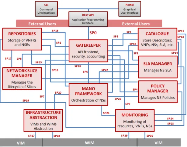
To an external user, meaning provider, developer, tester, 3rd party, etc, we could say that the most relevant component to them is the Gatekeeper. The Gatekeeper, as shown in Figure 1.2, is the component responsible to make public the SP’s APIs to the outside, ensuring that every access to the SP is done by authenticated and authorized users, first filtering invalid requests before they go further processed by the relevant internal component (web micro-services). The Gatekeeper is also responsible for get Descriptors from the Catalogue, enforce licensing models (through the Service Level Agreement (SLA) Manager) and enrich the requests with other data.
The Gatekeeper interacts internally with the remaining components of the SP:
The Catalogue whenever descriptors of packages, services, functions, slices, SLAs and Policies are requested
The MANO Framework whenever a service instantiation, service instance termi-nation or service instance scaling is requested
The Repository whenever records for instantiated services and functions are re-quested
The Slice Manager whenever a slice template is created or requested and a slice template instantiation or termination is requested
The SLA Manager whenever an SLA is created or associated with a service The Policy Manager whenever a policy is created or requested
The Infrastructure Abstraction (IA) whenever there’s the need to configure it with VIMs and WIMs, and also to know which infrastructure is available, and create or delete networks between services of the same slice
the Monitoring Manager whenever a developer wants to extract some monitor-ing data related to the services and functions he has developed and that were instantiated
Figure 1.2: SONATA SP main components and internal interfaces
Another component, which relies on the Gatekeeper but is its user friendly interface, is the Portal, which is an Angular application responsible of showing not only information regarding every component in the SP but also giving the possibility of executing oper-ations such as service and slice instantiation, SLA operoper-ations and attachment of new VIMs and WIMs among others. Release 5 is going to include a dashboard with useful monitoring data.
The usage of DevOps is one of the main features of SONATA, which is deployed easily using a combination of Ansible [13] Cookbooks and a Jenkins [14] automation server. Each different module runs inside a docker container, and all components are connected to the same virtual network bus, although not all components communicate with the rest of them. One of the main advantages from the developer point of view is that each component can use their own preferred language, (e.g. Java, Ruby, Python, An-gular, R...) depending on the development team that has designed and developed the component.
Finally, it is worth mentioning that one of the efforts of this work has been extending IA, in order to allow SONATA SP to manage CTTC´s WIM, thus giving a solution to a multi-PoP through an SDN WAN.
1.1.2.2. OSM
OSM is an ETSI-supported effort to develop an Open Source NFV MANO software stack compliant with ETSI NFV. Novel features in last release (Release 6) include Network Slicing, support for Physical Network Function (PNF), policy and monitoring and support for VNF configuration. There are multiple VIM that can be registered coming from a variety of companies or foundations, such as Openstack or Open-Vim.
There are some design modules and runtime modules. From developer point of view, he can operate using a web Graphical User Interface (GUI) or a Command Line Interface (CLI). The OSM CLI client uses directly it´s NBI API to remotely interact with the platform. It also can be used as a python library, and develop using it. Design time components are those which provide DevOps support and also give some computer aid when creating a VNF or NS package.
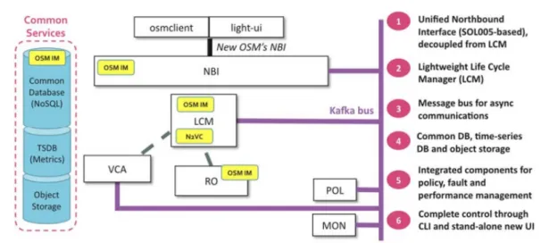
Runtime modules are those which give functionality during lifecycle events or post-configuration tasks to OSM, are shown in Figure 1.3 and listed below:
Unified Northbound Interface (NBI). The NBI component is providing the primary API endpoint into OSM
Lightweight Life Cycle Manager (LCM). It is responsible for all aspects of service orchestration including lifecycle management or NS and network slices, and ser-vice primitive execution. It is effectively the ‘master’ orchestration component in the system. Also, it is responsible for supporting the concepts of multi-tenancy, projects, users, and enforcing role-based access controls
Resource Orchestrator (RO) is responsible for managing and coordinating resource allocations across multiple distributed VIMs and multiple WIMs. Also, each VIM and WIM Plugins are responsible for connecting the Resource Orchestration Engine with the specific interface provided by the VIMs and SDN controllers
VNF Construction and Abstraction (VCA) is responsible for enabling configura-tions, actions and notifications between VNFs and/or Element Managers
Monitoring (MON) collects and also evaluates data retrieved both from VNFs and VIMs, and also can raise some alarms that trigger lifecycle related events
Policy manager (POL) is a module where alarms triggered by monitoring events are defined
A common Information Model (IM), which is common between much of the com-ponents in OSM. OSM, in fact, is based on a model-driven architecture.
Figure 1.3: OSM architecture diagram with different components
1.1.2.3. ONAP
ONAP is a Linux Foundation open source initiative with the support of AT&T and China Mobile among other companies. The ONAP project [15] addresses need for a common automation platform to deliver differentiated network services on demand, profitably and competitively, while leveraging existing investments. Figure 1.4 shows the deployment of a 5G network using ONAP. ONAP support container-based network functions, lighter than usual VNFs so the deployment time and resource usage becomes reduced.
Figure 1.4: ONAP 5G Use Case examples
1.1.3. Virtualised Infrastructure Management
Virtualization is the first technology enabler of Cloud Computing. Server virtualization allows to share physical server resources (CPU, RAM, storage, ...) over different virtual instances. Server hypervisors are software appliances which can run over bare-metal hardware or over operating systems.
However, cloud systems are moving to a layer of software above the hypervisor so-called cloud orchestrator system software. While hypervisors are able to provide resource abstraction in a single server, cloud systems can abstract large pools of compute, storage and network resources over the same software platform, thus realizing the concept of IaaS described before. This resources can be managed through a set of APIs to provide a holistic view of an infrastructure. A cloud provider can manage its entire datacenter (DC) over this cloud orchestration system to offer different cloud services to different tenants. Among the cloud orchestration software available, OpenNebula, CloudStack and OpenStack, are found as the most complete and mature solutions in the open source domain.
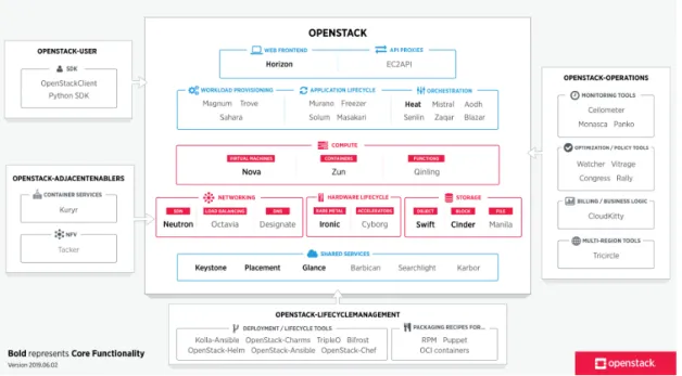
OpenStack [16] is the leading open source cloud orchestration platform used within DCs operated by cloud service providers and large enterprises alike. Development is supported by a broad base of developers and a growing cohort of commercial software and hardware vendors.
OpenStack is an open source project carried out by the OpenStack Foundation whose purpose is to provide a rich software platform which be able to provide the creation of cloud applications with many virtual instances controlling distributed storage among different servers in a clustered environment. The framework has an extensive amount of modules, following a micro-services architecture as we can see in Figure 1.5. Some of them are Nova, Glance, Keystone, Ironic and Neutron; which are responsible of the orchestration of different resources: Computing, Storage, Identity management, Bare-metal support and Network resources, respectively. Other modules, such as Heat, can be used to deploy a series of related VNFs, connected between them, conforming in the end a NS.
1.2.
SDN-based Network Orchestration
Software Defined Networks (SDN) are becoming an esential part on how not only opera-tors can manage their transport networks, but how functional blocks are connected in a DC. It also becames a principal actor when it comes to NFV enabler. A large number of VIM and WIM blocks uses SDN for enabling connections between different PoPs. The standard, beign defined by Open Networking Foundation (ONF), decouples the data plane from control plane, and also supports the programmability of how connections are created. That allows that a NFVO can use it to perform the so-called ‘orchestration’.
1.2.1. Application-Based Network Orchestrator
When deploying services accross different network domains through per-domain SDN or active stateful Path Computation Element (PCE) controllers, it is needed an entity to support such end-to-end connectivity by orchestrating. This component is called Multi-Domain SDN Orchestrator (MSO) and it is depicted in Figure 1.6. The MSO considers the heterogeneous underlying network resources (e.g., multi-domain, multi-layer and multi-control network resources) and it assumes that the underlying SDN controllers can to provide network topology information and flow programming functions. The MSO enables multi-layer and multi-domain network orchestration and it has to implement different plugins for each SDN Controller, which are typically technology and vendor dependent since there is not an standarized one.
Provisioning Manager
Network Orchestrator Controller
TED Topology Server VNTM FlowDB Flow Server PCE ODL … AS-PCE ODL…AS-PCE
Figure 1.6: Multi-domain SDN Orchestrator architecture
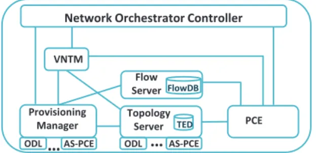
The MSO architecture is composed by the following components: Network Orchestration Controller, Virtual Network Topology Manager (VNTM), Topology Server, Provisioning Manager and PCE. This architecture is based on the Application Based Network Orches-trator (ABNO) framework [17], which has been standardized by Internet Engineering Task Force (IETF). Following, we briefly describe the main role of the components:
The Network Orchestration Controller is in charge of handling all the processes involved and to provision end-to-end connectivity services. It also exposes a NBI to offer its services to external applications
The Topology Server is the component responsible for arrange the network topol-ogy, collecting each sub-topology components from each different domain and building the whole network topology which is stored in the Traffic Engineering Database (TED). The TED includes all the information about network links and
nodes, and is used by a dedicated PCE for calculating routes across the network. Moreover, it requires to have some inventory information for some operations VNTM is responsible for the multi-layer management. In the proposed architec-ture, the VNTM arranges the establishment of an optical connection, which is then offered it as a logical link to the upper layer to satisfy any incoming connectivity demand. Also takes care of Network Abstraction in a multi-hierarchical scheme The Provisioning Manager implements the different provisioning interfaces to com-mand the forwarding rules and the establishment of connectivity segments into the data plane. An internal database stores each connection, and every network con-nectivity service along with the connections constructing it can be accesed using NBI API
The Operations, Administration and management (OAM) takes care of notifica-tions and events, consumed or produced from/to NBI or SBI, such as link failures or node additions, bringing the possibility of self-healing
1.2.2. ONF Transport API
Nowadays, the capacity to orchestrate multiple technologies and domains is key. As it was said before, usually SDN Controllers offer proprietary interfaces or, at best, open yet no standardized interfaces, to applications. These interfaces can be used by higher level controllers or other functional layers such as Network Orchestrators. Such SDN Controllers are arranged following an approach commonly referred to as ‘vendor domains or islands’. This heterogeneity, due to having different controllers interfaces in a multi-domain context, forces the use of ‘plugins’ and it is difficult and costly to implement. As a driving motivation and clear problem statement, there is a need for a standard interface, with common models, to act as a controller NBI.
Figure 1.7: T-API high level functional architecture and interfaces
The Transport API (Transport Application Programming Interface (T-API)) [18] pub-lished by the ONF meets the main requirements to be a protocol and interface used
between an orchestrator and multiple domain controllers. Figure 1.7 shows how a T-API based controller offers multiple services, being the more importants the topology and connectivity services. The services are modelled in the YANG modelling language. The T-API context is the shared information between a T-API client and the T-API server, which controls a SDN network. A Service Interface Points (SIP) is a pair of a network node and a port of that node (an interface) where a service can be relied to a client. The model defines a T-API domain as being able to provide services between different SIP mainly characterized by their universally unique identifier (UUID). Most basic operation for a client is to ‘retrieve’ the context in order to obtain the list of SIPs, so connectivity services are established between two (or more) exported SIPs.
If a given T-API server supports topology model, it augments the T-API shared context with a list of topologyies. Each topology is composed of a list of nodes, which, in turn, have Node Edge Points (NEP). Links connect two NEPs. The model is flexible enough to support recursive topologies and different levels of abstraction. The level of detail exported is configurable by policy. A client is then able to obtain an more simplified graph of the topology and map T-API SIPs to external NEPs.
Finally, the instantiation of a Connectivity Service relies on the instantiation of several connections (e.g. one end-to-end and internal at each T-API node). To this purpose, Connection End Points (CEP)s are instantiated over NEPs (and contain information about the connections) and connections involve two or more CEPs. T-API will be used as a key interface between network controllers associated to different domains, allowing end-to-end transport connectivity services.
DEPLOYMENT OF REAL TIME
COMMUNICATIONS SERVICE: USE
CASES DEFINITION
In this chapter we present how the problem was designed in early phases of 5GTANGO. How use cases drive us to solve different challenges is described in Section 2.1, and Section 2.2 further comments about how QoS enforcement is necesary in the pilot. In the context of 5GTANGO project Work Package (WP) seven, there are 3 different pilots, all of them related with vertical output to industry, in basis of different usecases defined for each technology. Those pilots are:
Smart Manufacturing Pilot is an effort for bringing new 5G technologies to old manufacturing industry processes
Immersive Media Pilot is an approach to Augmented Reality, where a user can experience the watching of a video with a dashboard with social networks or live data
Communications Pilot deploys a video-conference service that can host up to a high number of users using the same NS, with different levels of service depending on the license purchased by each client
This Master Thesis focuses on several aspects of the Communications Pilot. There are four different use case deployments, each one posing a different problem which have been considered for this pilot to cover, all of them further explained in the chapter 2 of deliverable 7.2 [19] of 5GTANGO project. These use cases are a Best Effort (BE) video-conference service, a premium video-conference service, an edge video-conference service and finally a video-conference service that offers the possibility of scaling when required.
2.1.
Communications Pilot Use Cases
2.1.1.
Centralized video-conference services
The first use case is BE video-conference, which does not takes advantage of QoS management, as shown in Figure 2.1. This use case can provide service to users that are connected to an access node, being the NS instantiated in the core, across an SDN fabric. When the service is instantiated, is necesary that the provider configure correctly which are the client border endpoints, for the placement and the WIM wrapper modules in the SP side and the WIM itself perform provisionining operations on the network to have it connected in a proper way. In the experimental deployment, up to four border nodes are available, meaning they are are ready to be used by this service.
Figure 2.1: Use Case 1: deployment of one centralized service
2.1.2. Premium and best-effort QoS video-conference services
The second use case is similar to the previous one, but with the difference of using QoS enforcement if required, and is ilustrated in Figure 2.2. QoS can be parametrized by some conditions required by the client, and collected by a license and a SLA asociated to the service instantiation: a certain bandwidth needed for that service, or by a certain low-latency conditions, both of them can be critical in case of a high quality video streaming or other real time applications. In addition, other relevant QoS parameters are monitored by the SP, such as jitter, users connected, packet loss measured by the application, appart from those which are also monitored by WIM. These parameters can raise alarms at the SP due to SLA violation, and eventually trigger some actions regarding VNF life cycle such as scaling and VNF migration, but are not used in this use case.Besides, this use case uses DF, following ETSI NFV SOL001 [20], to define different configurations within the same NS and have a different performance or behaviour profiles depending on the usage intended or SLA chosen by the provider to deploy it, and allowing variable resource assignation.
2.1.3.
Edge video-conference services
As seen above, in some scenarios it may be required to deploy video-conference services closer to the end users in order to reduce the End-to-End (E2E) delay, since it may exceed the maximum desired threshold and the system may not fulfil customer SLAs. Under this assumption, in the third use case two scenarios (see Figure 2.3) are considered. In the first scenario, we consider that all the video-conference NSs are in an edge NFVI-PoP(e.g. small-DCs in central offices located in the aggregation/metro network).
In a second scenario, we consider that instead of deploying the whole video-conference NSs on an edge NFVI-PoP, we shall deploy only those NSs that are delay-sensitive for a proper operation and those which are not constrained remain in core-DC. In this case, the design of the NS must be defined to somehow tag those VNFs that are constraint to be deployed in the edge NFVI-PoP, and SP must give the posibility of having a multi-site
Figure 2.2: Use Case 2: deployment of two networks services, Gold and Silver connection.
Figure 2.3: Use Case 3: deployment of VNFs closer to the edge
2.1.4.
Video-conference scaling out/in services
Finally, the fourth use case is related with the introduction of dynamic scaling, which is add or remove strategicaly critical VNF replicas, that without this functionality would be the cause of a bottleneck in terms of performance. In the video-conference NS there are two VNFs that can be scaled in/out. These VNFs are the VNF-WAC and VNF-MS. A monitoring service will check registered and connected users (from VNF-WAC), and also concurrent number of conferences being executed and bandwidth usage(from VNF-MS), and when certain conditions are reached, to keep Key Performance Indicators
(KPIs) under control, the scale in/out operation is performed by the SP without the user becoming aware of the process. This use case infrastructure is similar as the previous ones.
2.2.
Communications Pilot and QoS enforcement
The ability to provide differentiated qualities of service is an old objective in network engineering. Different QoS levels are required for different customers (who subscribe different packages with different prices) or to accommodate the requirements for different services. Services like voice, video or more recently Virtual/Augmented Reality services have more strict requirements.
QoS parameters in NFV can be specified in a flexible manner either on the VLs or in connection points of the VNFs attached to them, referenced in NSD and/or VNFD. When the QoS is defined on connection points scope, it applies to the outgoing traffic (unidirectional QoS), while when the QoS is defined over the VLs, it applies to all connection points of that network, also for the outgoing traffic (bidirectional QoS). The QoS parameters in descriptors (NSD and VNFD) can specify VL that later on will be provisioned ‘internally’ in a PoP by a VIM or provisioned ‘externally’ in a WAN, by a WIM. The scope of this project is the ‘external’ extended VLs, where the WIM performs the QoS enforcement.
This master thesis focuses only on use cases one and two, which refers to a BE video-conference service and a service that can provide QoS differentiating between premium and non-premium users.
ARCHITECTURE
In this chapter, we describe a number of tasks developed in order to give support to the pilot. Section 3.1 describes how NFVO platform has been modified adding the needed functionalities in other components not including the new WIM wrapper, while Section 3.2 gives an in-depth description of the new component developed, giving the capacity to perform placement across a SDN WAN. Section 3.3 dives into the video-conference service descriptors and components, and finally Section 3.4 details how are the workflows that take place when instantiating a network service with the new functionalities. In the previous chapter, we presented several use cases stating several problems not yet resolved to which solutions have to be implemented, to achieve the objectives and expectations of 5GTANGO and more specifically the pilot.
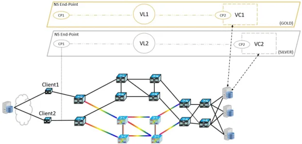
Figure 3.1 shows a general view of key points that have been developed under this thesis effort. On the left side, we have two nodes named hereafter Client1 and Client2, which are outside the elements controlled by the WIM, although they are connected to the WAN so they can be provisioned by using it. The video-conference service (VC) NS is instantiated in the Core-DC PoP (in the right side of the figure), and external VL means an abstracted connection from ingress connection point (CP1) mapped to clients, with egress connection point (CP2) mapped with the NS. VL is created across the WAN, a network connection performed by the WIM functional block. Depending on QoS requirements, VL underlay will be optical-electrical for a more restrictive QoS or on the contrary it will be routed through only-electrical nodes. Thus, all elements are put together to work in order to achieve an operational service. Details of each component are further explained below.
Figure 3.1: NS deployment with two network services, Gold and Silver and two shared clients each
3.1.
Extensions to NFV Orchestrator
Currently there are two main deployment cases where a WIM wrapper can be used, subject of the actual WAN technology and management:
Case 1: Programmatic Network Control (i.e. SDN based) This case is considered as the primary target for a WIM Wrapper, aligned with the view of ETSI NFV. Underlying networking infrastructure is controlled by Network Controllers that sup-port SDN API interfaces, thus the WIM interfaces with those Network Controllers in order to provide multi-tenancy, programmability and isolation summarised as Network as a Service (NaaS).
Case 2: Non-programmatic Network Control, controlled using ‘legacy’ Network Management. This case is considered where actual programmatic interfaces are not available (e.g. NETCONF) and where casual Network Management Systems are used for the resource management and operation of the WAN infrastructures. In this case it is expected that the service requests will be signalled through the OSS/BSS system and not directly through the WIM.
Also, it is convenient to say that usually, in a real scenario, the infrastracture is not purely ‘Case 1’ or ‘Case 2’ but something between them, islands of SDN among a sea of legacy networks or viceversa. It´s important to consider any ‘in-the-middle’ scenario. TANGO´s NFVO, has been extended to support WAN management through a T-API interface. The new component is integrated in the IA module, which already had a Virtual Tenant Network (VTN) wrapper to interact with a WAN controlled by a single OpenDaylight (ODL) controller.
This solution is quite limited, since ODL is a pure SDN controller, thus it cannot operate over other kind of technologies, such as GMPLS/PCE optical networks, or more complex transport WANs. Moreover, this solution is not scalable, since one ODL controller will start to drop on performance (latency, control interface saturation) when controlled nodes start to rise, not mentioning a geographically distributed infrastructure where conditions are even worse.
As a result of previously mentioned problems, and new use cases planned to develop for communications pilot (See Chapter 2), the need of a new wrapper arises, one that can give support to an a distributed NS through a transport WAN. This can be done by NS extension, as it is described in [8, 10].
From a high level point of view, this extension to NFVO is the provision of a NaaS, but limited. WIM topology service is not fully available for SP operator, for this reason, there exists the possibility of using T-API NBI and the wrapper can create VLs between VNFs located in different NFVIs (multi-site NS) or create services on instantiation time to give customers E2E connectivity and reach the service external interface endpoint. How this connectivity services function and are designed is further explained in Subsection 3.2.1. These VLs are referenced both from VNFDs and NSD corresponding to a service, in SONATA SP they can be grouped in three types: E-Line, E-Tree and E-LAN. These three connectivity types are named after MEF Carrier Ethernet specification1, and
sum-marizing:
E-Line is a point-to-point service
E-Tree is a point-to-multipoint ethernet connection
E-LAN is a multipoint-to-multipoint connection, behaviouring equally than an Ethernet HUB
SONATA MANO calculates placement in basis of those three kind of VLs, so it´s im-portant to have a well defined VNF topology, to keep the minimal number of logical connections. That is key to improve performance (reducing overall traffic), and avoid possible security flaws, keeping out of the picture undesirable ‘doors’.
VL terminations are called connections points (connection_points field in the VNFD), a list in the VNFD with each interface that the corresponding VNF has. These connection points can be of three types: internal, external and management. Internal connection points are for connections between VNFs or VDUs within the same NS, external con-nection points are those which are exposed to access from outside, through dataplane andmanagementis the interface where corresponding Function Specific Manager (FSM) accesses to perform configuration modifications. Having at least onemanagement con-nection point is mandatory, while external and internal interfaces are not, but there is not a limit of how many connection points can have a VNF/VDU. After all, each connection point is mapped to a virtual interface inside the VNF image, when it is instantiated. When using DFs, each flavour can vary on the number of VNF used (e.g. a High Availability flavour can have two external interfaces instead of one) and also have different QoS parameters. Supported QoS parameters are Bandwidth limit, Minimum Bandwidth, Maximum Latency and Differentiated Services Code Point (DSCP) Marking.
After every bit of information is mapped from the Yaml model by MANO, while on placement phase, information from VIMs and WIMs attached to the SP. In Communica-tions Pilot, there are two Openstack deployments, thus onlyHeat wrapper takes action, while on the networking part there is an ABNO/T-API WIM. In the VIM part, a Heat Template is created, mapping each element found in the descriptors, to a Heat resource. After the NS is instantiated (this process might be long, depending on how many VDUs are forming it), FSM modules take action, performing configuration tweaks and checking that every VDU is working correctly.
3.1.1.
T-API WIM IA Wrapper (
tng-sp-ia-wtapi
)
This leads to notifiying the WIM block, if it is necessary for it to take action. Further-more, WANs must be SDN and controlled by attached WIM. There are two possible scenarios when this can occur:
When the instantiated NS is distributed among two or more NFVI-PoPs
When the instantiated NS external interfaces are to be connected to external network endpoints (customer nodes)
WIM wrapper is directly attached to the IA SONATA´s SP, and when one or more T-API WIM(s) is (are) registered in the SP, it retrieves useful information about the topology.
A new type of VIM element calledendpoint has been defined, each of those is a SIP (a T-API object) stored and exported by WIM. Theseendpoints are stored in IA database, so it can access then and make them public to the rest of SP modules. This component has been developed using Python 3.6, which is a very spread, easy to maintain and develop language.
Some of the fields within SIP object record are name, geo-location (city and country), type and description. Name is an important field, since it is the field where endpoints corresponding with an specific VIM are correlated, to do subsequent operations. Type is also important, since it indicates if the SIP is a customer endpoint, SP management (see Subsection 3.1.3 or a PoP.
When a service is about to be instantiated from any interface of the SP, the customer can define these endpoints as ingress or egress attachements to the instantiation parameters that comes to MANO. It connects each external interface of the NS to eachendpoint, also taking into account some qos parameters, that are processed and sent to the wrapper. Communication between MANO, IA-NBI (acting as a broker) and WIM wrapper is done using Advanced Message Queuing Protocol (AMQP), with three routing keys configured to trigger the wrapper: infrastructure.tapi.management.wan.list, infrastruc-ture.tapi.wan.configure and infrastructure.tapi.wan.deconfigure.
When a VL is to be created using the wrapper, a message comes through infrastruc-ture.tapi.wan.configure, with a payload as shown in Appendix B, whose fields are ex-plained below:
service_instance_id: UUID corresponding with the one asigned by the SP to the NS instance whom this VL depends
vl_id: String corresponding with the one specified in the NSD to identify this VL wim_uuid: UUID which identifies the WIM where the wrapper is going to provision the connections
ingress: It has two fields, one is the endpoint UUID to which the connection has to be provisioned and the other is an ip segment, which will be allowed to connect to/from egress endpoint
egress: Contains the analogous contrapart of ingress. It is the other endpoint of the virtual link
qos: Contains parameters regarding QoS requirements (if any included in the descriptor), e.g. minimal or maximum bandwitdth, maximum latency, or other bidirectional: A boolean indicating whether the VL is connected as an undirected graph edge or as a directed one
For deconfiguration, a message comes through routing keyinfrastructure.tapi.wan.deconfigure, onlyservice instance id,vl idandwim uuid fields are included in payload, and using them the connectivity services which enable the VL become to an end. This is done as first block in theinstance termination pipeline of the NFVO. Both configure and deconfigure can be found in more detail in Section 3.4.
Both SONATA project and its extension 5GTANGO components are stored in this GitHub project, using a Continuous Integration/Continuous Delivery (CI/CD) approach on how components are developed. First, component is tested in a pre-integration environment, where a pull-request updated image is deployed over the current component container. When the component is well-tested, it follows to integration environment, and it follows more steps until is release-ready. Using this way of function, allows the whole team to check common logs and report bugs easily. Check T-API wrapper´s GitHub repository [21] for further information.
3.1.2. QoS support
QoS parameters coming in VL configuration are parsed and translated to a proper con-nectivity service by wrapper. As it was said before, available QoS parameters are in this case related with bandwidth and each of them are sent to the WIM to be processed. Bandwidth is used in our case to differentiate between silver and gold flavours. When bandwitdth is higher than a known threshold, if resources are available, the path will be routed through the optical domain, otherwise, the path will be electrical only. gold
flavour then uses the higher minimum bandwidth parameter (see 3.3.1).
Latency is also a parameter to be taken into account. Low latency use cases are very common in 5G and one of the promises is the availability to make this latency come to a real case. However, latency is not a deterministic measurement, and after doing some testing, we decided to use only bandwidth for differentiating flavours, and while this maximum latency is still forwarded to the WIM, we lack of the monitoring framework for getting this measurements in real time.
Other QoS measurements, such us jitter or packet loss, have similar problems than latency, but one step further, since without application monitoring data (to have real time mesurements) or probes between customer and VNFs, is not possible to measure this parameters.
3.1.3.
NFVI-PoP interconnection
As stated in 1.1.1.3, interconnecting NFVI-PoPs is a common use case in NFV. Dataplane connectivity is abstracted from descriptors, being possible to have a service of two VDUs and a single VL, instantiated in a single NFVI-PoP or in two different NFVI-PoPs without the customer realising this fact. This use case, as mentioned, can be due to lack of enough resources in single NFVI.
Moreover, if there is a WAN (which could be a single switch node to a complex transport network) connecting both NFVI-PoPs, a WIM intervention must take place in order to allow the correct operation of the running NS. This multi-site NS instantiation is not limited to two PoPs, but instead the number of PoPs that could take part in it is only limited by the number of VNFs that form part of the NS. For allowing SONATA to have this new functionality, more changes in modules were implemented.
Apart from the WIM T-API wrapper, several components where to be updated: portal,
gatekeeper,MANO andIA, to include qos support, and new placement primitives. There was a notable work done by MANO and IA developers, which had also included QoS
support. Descriptor models where also changed, and that included more components outside SP, the group called SDK, changed, to update the design phase. All this new changes are going to be included in a new SONATA framework upcoming release. Fur-thermore, in the specific WIM T-API wrapper, there were two specific problems to be tackled in order to allow this multi-site connectivity.
On one hand, Openstack deployments in SONATA are only compatible with the usage of an virtual internal router (an Openstack resource, dependant on Layer Three (L3) agent ofneutronservice) to give connectivity from/to the external network to/from each VNF is done by the use of a concept called floating Internet Protocol (IP)s, which in the end is a concept very similar to doing a Network Address Translation (NAT). Virtual router runs in a new namespace [22] inside Linux kernel, and new router interfaces can be created and attached to private tenant networks inside the openstack deployment (see Figure 3.2. In this figure, we can see a provider network which is accesible from outside without passing through other elements (blue bus), and other networks that are not directly accesible from outside, however, internal networks (colored in orange, green and red) are connected to the virtual router, and each VL is representd by each one of these internal networks.
Figure 3.2: Openstack provider (blue) vs private (orange, green and red) networks com-parison
As a consequence,floating IPs are assigned to each VNF interface which type is whether management or external. Afloating IP pool is defined, and this pool has to be included by provider´s subnet range. Floating IPs are assigned by the L3 Agent ofNeutronservice. To allow connectivity to this addresses, customer endpoints must have connectivity to
the virtual router, appart from to the VNF. This is the consequence of the router acting as proxy-Address Resolution Protocol (ARP) to the VNFs.
Besides, in our specific deployment, VNF management plane is shared with data plane. Because of this, a management service has to be created, which allows connectivity between every IP contained in thefloating IP pool, also including the external IP assigned to the virtual router. A dedicated interface of the server running the SP is the contrapart of this ‘management connectivity service’. Some SP components (e.g. FSM, Service Specific Manager (SSM), monitoring service, etc) use this connection to reach the target PoP and it hosted VNFs.
3.2.
Network Management with WAN Infrastructure
Manager
WIM model and definitions has been well defined by ETSI NFV work group, as explained in Subsection 1.1.1.1 entry for this functional block. CTTC premises are controlled by his own network orchestration suite [23], which takes care of topology retrieval for multiples topologies, and provisioning for the required connectivity services, using several plugins for each different domain. This plugins allows interfacing with:
Pure SDN domains, where there are several Openflow Software Switches, con-trolled by a SDN controller, i.e. ODL, Open Networking Operating System (ONOS) or Ryu. Each controller has its own API
Optical - Electrical transceiver nodes, which have their own API
Optical colorless domain, controlled by a Active Stateful Path Computation Ele-ment (AS-PCE) and using Path Computation EleEle-ment Protocol (PCEP) to com-municate. Plugin uses an implementation of a Path Computation Client (PCC) Hierarchical control, where other controllers or orchestrators can be stacked in a multi-level architecture and use Control Orchestration Protocol (COP)
Also, there are plugins to allow connectivity between domains, defined in an Extensible Markup Language (XML) and also there is the posibility of having a complex network virtualized. In this work, network is not virtualized, but when an optical lightpath is created, which means that there is an optical circuit, a virtual link is created between the two border nodes involved. New connections can be groomed if the network is yet capable of supporting more bandwidth usage. When the link usage is almost at full capacity, a new optical link can be created, using spatial multiplexing.
In ADRENALINE Testbed there are currently three ODL controllers, one at the edge network close to the access nodes, one emulating a metro network between the edge and the core and one at the core emulating a core network and a DC. Also, in parallel to the metro network using packet switching, there is an optical circuit network using AS-PCE. All of them are considered theTransport Network in the Pilot.
In SDN domains controlled by a ODL controller, there´s a controller´s service that takes care about Topology Discovery. This service makes Switches to send Link Layer
Discovery Protocol (LLDP) packets through every port (as Spanning Tree Protocol (STP) does in legacy networks), but also an Openflow rule is created in each Software Switch (or Physical Openflow Switches), to report that packet to the controller. These packets contain information about sender´s identity, what is called OpenFlow Datapath ID (DPID), and is a unique identifier of each Openflow Switch. Thus, ODL controller can compute DPIDs connected within each other, and make a topology graph.
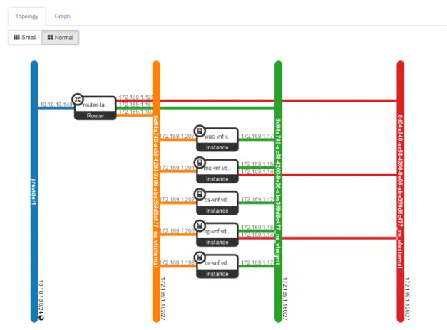
Edge sub-domain (see Figure 3.3) is composed by two software switch nodes, running OpenVswitch 2.6.6 over Ubuntu 14.04.6, which are, from the point of view of the ODL controller that governs over them, isolated, since there is no direct link between them. However, when this topology is imported, and conformed by the ABNO WIM, network graph connects each of this two nodes to an Optical Control-plane Controller (OCC), which translates into this node connected to the optical dataplane. Additionally, the physical connection is performed by the use of optical Myri PCI Cards [24] using 10 gigabit small form factor pluggable transceiver (XFP) modules. Also, each node has a link to two of the nodes which are integrated in metro sub-domain.
Moreover, Edge sub-domain nodes give connectivity to one edge cloud, containing an Openstack cluster composed by two nodes, representing a Central Office (CO), one of each is connected to one of the switch nodes. Also, four Next Unit of Computing (NUC)s act as client aggregators, and also are distributed among the two nodes.
Figure 3.3: Edge sub-domain topology shown in Opendaylight web GUI
Metro sub-domain (see Figure 3.4) is composed by four Software Switch nodes, running OpenVswitch 2.10.0 over Ubuntu 18.04, which in this case are connected in a diamond topology, as shown in the figure. These nodes are fully packet switched, representing a metro network with ethernet connections. Each one of the four switches has an outgoing connection to edge or core subdomains. In this case, no other network or compute elements are connected to the switches. These nodes are also controlled by a ODL controller.
Core sub-domain (see Figure 3.4) is composed by four Software Switch nodes, in this case, two of them are running OpenVswitch 2.10.0 over Ubuntu 18.04 (DC-Switches) and the other two running OpenVswitch 2.6.6 over Ubuntu 14.04.6. These last two
Figure 3.4: Metro sub-domain topology shown in Opendaylight web GUI
mentioned nodes also are connected physically to the optical domain using XFP in the same way as the edge nodes are. modules In this part of the WAN the core-datacenterNFVI is located, which is an openstack cluster of three nodes whose dataplane is connected to both of the DC-switches.
Figure 3.5: Core sub-domain topology shown in Opendaylight web GUI
Finally, an optical sub-domain (see Figure 3.6), which is formed by four optical routing elements (two reconfigurable optical add-drop multiplexer (ROADM)s and two optical cross-connect (OXC)s), whose control plane is attached to four corresponding OCCs, and all of them associated with a AS-PCE node, which takes care of both topology export and optical resources provisioning.
Overall, these four sub-domains are ‘merged’ by the ABNO WIM and a new cross-domain topology (Application Topology) is created, as shown in Figure 3.7. Optical nodes are
Figure 3.6: Optical sub-domain topology shown in PCE web GUI
identified by the IP address of its corresponding OCC, and Openflow Switches by their DPID. This topology is the one that is available at WIM NBI API in JSON format, and also to perform connections, NFVO and furthermore OSS/BSS must use this topology or an abstracted version of it to perform routing algorithms and later placement on SIPs which have a PoP connected.
Service orchestration applies to the logic of the service as requested by the customer, identifying the functions needed to honour the customer request as well as the form in which these functions interrelate to complete the complete service. The service or-chestrator will trigger the instantiation of the NFs in the underlying infrastructure in a dynamic way.
By the right combination of service and resource orchestration, the E2E management and orchestration functionalities will be responsible for a flexible mapping of services to topologies of VNFs, based on a dynamic allocation of resources to VNFs and the reconfiguration of VNFs according to a changing service demand during runtime.
3.2.1.
T-API extension
As it was said in Subsection 1.2.2 T-API specification uses connectivity services to provision connections. These connectivity services can be created, modified or deleted using the NBI RESTful API, using a specific payload. Previously, only a connection between two SIPs can be created, as a result, every packet comming from SIP A to SIP B is forwarded, but that makes impossible a proper SDN path creation.
To give a solution to this problem, T-API was extended, to provide support to what is called amatch. Amatch, in SDN protocols (e.g. OpenFlow [25]) is meeting a condition through extracting a target field, and comparing it to a parametrized value, extensible to a collection of matches. If the condition is met, the action
![Figure 1.1: ETSI NFV architecture [1]](https://thumb-us.123doks.com/thumbv2/123dok_us/522229.2561494/18.892.135.755.442.881/figure-etsi-nfv-architecture.webp)