Scalable Network Architectures Using the
Optical Transpose Interconnection System (OTIS)
1Francis Zane
Department of Fundamental Mathematics Research,Bell Laboratories,Lucent Technologies, 600Mountain Avenue,Murray Hill,New Jersey07974
Philippe Marchand
Department of Electrical and Computer Engineering,University of California,San Diego, La Jolla,California92093
Ramamohan Paturi
Department of Computer Science and Engineering,University of California, San Diego,La Jolla,California92093
and Sadik Esener
Department of Electrical and Computer Engineering,University of California,San Diego, La Jolla,California92093
Received March 14, 1996; accepted November 18, 1999
The Optical Transpose Interconnection System (OTIS) proposed by Marsdenet al. (Opt.Lett.18, 13 (July 1993), 10831085) makes use of free-space optical interconnects to augment an electronic system by adding non-local interconnections. In this paper, we show how these connections can be used to implement a large-scale system with a given network topology using small copies of a similar topology. In particular, we show that, using OTIS, anN2node 4-D mesh can be constructed fromN copies of theN-node 2-D
mesh, anN2node hypercube can be constructed fromNcopies of theN-node
hypercube, and an (N2,:2,c2) expander can be constructed fromN copies
of an (N,:,c) expanders, all with small slowdown. Finally, we show how this expander construction can be used to build multibutterfly networks in a scalable fashion. 2000 Academic Press
Key Words:optoelectronics; OTIS; mesh; hypercube; expander; multi-butterfly.
521 0743-73150035.00 Copyright2000 by Academic Press All rights of reproduction in any form reserved. 1This research is supported by ARPA under Grant F30602-93-C-0173 administered by Rome Laboratory.
1. INTRODUCTION
In selecting an architecture for a parallel system, the choice of network topology inherently contains trade-offs. To make efficient parallel algorithms possible, the network topology should allow many connections between different parts of the network to avoid bottlenecks. As an example, one desired criteria might be that the network should have large bisection width. However, such networks are inherently difficult to implement in electronics because of the the fundamentally two-dimen-sional nature of the technology.
In principle, free-space optical interconnect technologies offer several advantages over electrical systems which can help to improve this trade-off. Optical signals can pass through one another without interference. Connections can be made at higher speeds with less crosstalk and less power consumption than electrical channels. The power required to send a signal is nearly independent of the length of the connec-tion, at least over the lengths of connections involved within a parallel machine. However, while point-to-point connections are more efficient in optics, optical signals are difficult to route. Some routing of optical links is possible using lenses and computer-generated holograms (CGH), but arbitrary connections are harder to implement as space-variant optics than as wires on a VLSI circuit, multi-chip module, or printed circuit board.
In this paper, we focus on a specific set of optical interconnects, the Optical Transpose Interconnection System (OTIS), which can be implemented easily using free-space optoelectronic technologies. By augmenting simpler, all-electronic networks with this set of extra optical connections, we show how rich network topologies can be realized more efficiently and obtain the advantages of both efficient global interconnections from optics and the routability of electronics. The results of this paper focus on fine-grained, massively parallel systems, consisting of many chips with many processing elements (PEs) per chip. The intention is that connections will be made electrically within each chip, and chip-to-chip com-munications will be handled optically. Since electronic connections are efficient over short distances and optical connections for long distances, this approach uses each type of communication appropriately.
We use this single, fixed set of optical interconnections to build large systems with rich topologies. For the topologies of interest, the area required to lay out such networks in VLSI frequently grows faster than linearly as a function of the number of nodes, implying that large systems must suffer substantial overhead in their implementation. To avoid this behavior, our networks will be built of small subsystems, where the overhead is not too large, connected together via optical interconnections.
We begin by presenting the OTIS optical system in Section 2, and some necessary terminology in Section 3. In the remainder of the paper, we consider dif-ferent topologies for the small subsystems, and we examine the improvements possible by adding optical interconnects. In Section 4, we show how a 4-D mesh can be emulated by the OTIS-Mesh, whose components are connected only by simple 2-D meshes. Similarly, in Section 5 we show that the OTIS-Hypercube network, which consists of many small hypercube networks connected optically,
can simulate a large hypercube. Finally, in the last two sections, we consider networks involving expander graphs, graphs with random-like properties useful in many routing and fault-tolerance applications. We first show how these expander graphs can be constructed using smaller expander graphs in Section 6, and then make use of this construction to build scalable multibutterfly networks, butterfly-like networks composed of expanders, in Section 7.
In related work, since the publication of an earlier version of this paper, several of these networks have been analyzed further. In particular, algorithms for many important basic operations have been given for the OTIS-Mesh [19, 25] and OTIS-Hypercube [20] networks.
2. OPTICAL TRANSPOSE INTERCONNECTION SYSTEM
The Optical Transpose Interconnection System (OTIS) is an optoelectronic Multistage Interconnection Network (MIN) developed for parallel processing systems [17]. In an OTIS-based free-space optoelectronic MIN, electronic bypass-and-exchange switches are required to do the local routing. It has been shown that for an optoelectronic MIN withN2
inputs andN2
outputs, the bandwidth and the power consumption of the network are optimized if the electronic switch planes are partitioned into Nswitches [13]. Thus, in an OTIS-based parallel system,N2
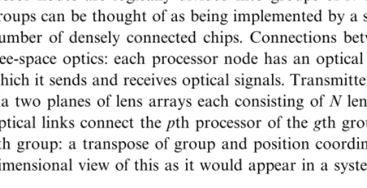
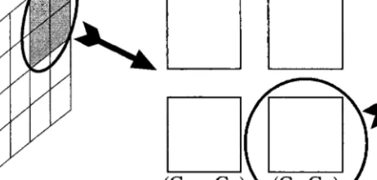
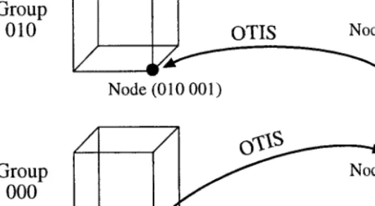
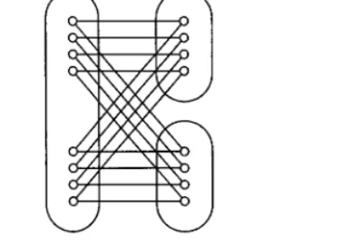
pro-cessor nodes are logically divided into groups of N nodes each. In practice, these groups can be thought of as being implemented by a single chip, or perhaps a small number of densely connected chips. Connections between groups are achieved via free-space optics: each processor node has an optical transmitterreceiver pair with which it sends and receives optical signals. Transmitters and receivers are connected via two planes of lens arrays each consisting of Nlenses, as shown in Fig. 1. These optical links connect the pth processor of thegth group to the gth processor of the
pth group: a transpose of group and position coordinates. Figure 2 presents a one-dimensional view of this as it would appear in a system viewed from the top or the
FIG. 2. OTIS systemSide view.
side. These optical connections can be thought of as higher order generalizations of the shuffle edges in the perfect shuffle.
The OTIS implementation offers several advantages for large scale intercon-nection networks. In general, optical technology offers the advantage that the bandwidth and power requirement of a link are independent of the length of the link. For example, it has been shown in the literature [6, 10, 11] that for line lengths greater than a few millimeters, free-space optical interconnections require less power for a given bandwidth. In addition, free-space optoelectronic systems also facilitate electronic layout due to the fact that the IO is performed over the 2-D area of the chip and is not limited to the 1-D boundary of the chip.
The OTIS optical architecture offers some additional advantages. The two-plane system pictured can be folded back onto itself with a mirror to establish connec-tions from a chip or a plane of chips onto itself. It can be made bidirectional to provide interconnections between two processing planes, or it can be cascaded to accommodate successive processing planes. It can also accommodate any arbitrary optoelectronic layout as long as the layout of all the groups are identical. Finally, the optics in OTIS can be designed to allow bit-serial andor bit-parallel com-munications between node (g, p) and node (p, g) in the system.
OTIS relies on optoelectronic flip-chip bonding technology and free-space optics. The integration of 8000 optical transmitters and detectors on a single 0.8+m silicon chip using flip-chip bonding has now been demonstrated [9]. A simple free-space optical system for which 4096 bidirectional channel connections has also been demonstrated [17]. To validate the concept of OTIS, an experimental chip has been built which combines electronic switches [12] with the AT6T technology for optoelectronic device integration on silicon. New systems based on the OTIS topology have been implemented using Vertical Cavity Surface Emitting Laser
TABLE 1 OTIS System Modelling
Total throughput 1 Tbitss
Total power consumption 55 W Optical power at the plug 10 W Electrical switch power 25 W Receivers electrical power 10 W Transmitters electrical power 10 W
Total silicon area 8.8 cm2
Longest electrical wire 2.2 mm
Powerchannel 13 mW
Areachannel 460_460+m2
Power density 5.6 Wcm2
Technology integrated with Silicon CMOS in a Multi Chip Module Environment. Results for these systems can be found in [26, 27].
Extensive modeling of an OTIS-based switching system using the OTIS-Hyper-cube topology has also been performed [8]. Performance of the system in terms of throughput and cost in terms of system power consumption, area, volume, and maximum power dissipation per unit area have been computed. The modeling includes the VLSI switches, the optoelectronic receivers and transmitters, the opti-cal interconnection system, and the main laser required to power-up the modulators and its associated optics. Note that in this modeling, it is assumed that the VLSI switches contain circuits to detect hot spots and allow the OTIS network to resend data packets that have been dropped due to contention [12]. This model-ing also assumes a smodel-ingle switch plane and the required optics to fold the intercon-nections back onto the chips. Table 1 gives the results of this modeling for a 4096-channel system running at a clock speed of 125 MHz.
The modeling results of the OTIS-based switching system are very encouraging in terms of the feasibility of a large-scale implementation (4096 channels) of the system. It can be seen that although the required silicon area is quite large (8.8 cm2) it can be tiled into smaller chips since the longest wire is only 2.2 mm long which makes multichip module implementation relatively easy. As mentioned previously, OTIS will be able to accommodate such a layout. In addition, a total power requirement of 55 W is low for such a large system and the power density projec-tions (below 10 Wcm2) remain within air cooling limits. If packaging issues related to integrating free-space optics with optoelectronic chips can be resolved at a reasonable cost, this system would prove competitive with electronic alter-natives [5]
3. TERMINOLOGY AND ASSUMPTIONS
In the rest of the paper, we present emulations of various topologies by networks augmented by OTIS. OTIS systems described in the remainder of the paper consist of one plane of chips with optical connections folded back onto itself. In order to
keep the notation simple, N refers to the size of a group in OTIS (i.e., OTIS networks have size N2.) Also, OTIS processors will be referred to by pairs (g, p), wheregrepresents the group the processor belongs to andprepresents the position of the processor within the group. The basic topologies used (mesh, hypercube, expander) refer to the connections within each group. The optical transpose links, which connect nodes (g, p) and (p, g), provide the only connections between nodes in different groups. We also make a few additional assumptions for carrying out the emulations. All links are assumed to be bidirectional. The mesh and hypercube networks are assumed to run in SIMD fashion; that is, each node is allowed to send along only one of its edges at any time, and this choice must be uniform for all pro-cessors. Since such a definition would not make sense for the expander, we assume the stronger property that each node can process a message per edge. If this assumption is made in general, the other two networks can be used in MIMD fashion. If the optical links run at the same speed as the electronic links, this MIMD simulation will be slowed by contention for the optical links. If the optical links can rund times faster for a degreednetwork, no additional slowdown will be incurred. Faster optical than electrical communication speeds are certainly sup-ported by the current and projected technologies; the difference between the two speeds in an integrated system is more difficult to ascertain.
When analyzing the layout area required for various systems, we use the Thompson grid model [21, 22], which assumes that all nodes and edges lie on a grid, at most two edges cross at a point. We measure area by the size of the bound-ing box required to contain the layout. Usbound-ing the techniques developed in these works, a graph with bisection width B requires area at least 0(B2). Finally, any constant-degreeN-node graph can be embedded usingO(N2) area with a crossbar.
4. OTIS-MESH
We begin by considering the case where each group of OTIS has the very simple 2-D mesh topology: each node is connected to the nodes which lie to the north, south, east, and west of it within the same group. Since each node has degree at most four, and every connection is short, 2-D meshes are simple and can be implemented with a single level of electronic wiring. However, for the same reasons, the 2D-mesh topology is quite weak, having a large diameter and (relatively) small bisection width. Here, we examine the architecture which results from adding the OTIS connections to a collection of 2D-meshes.
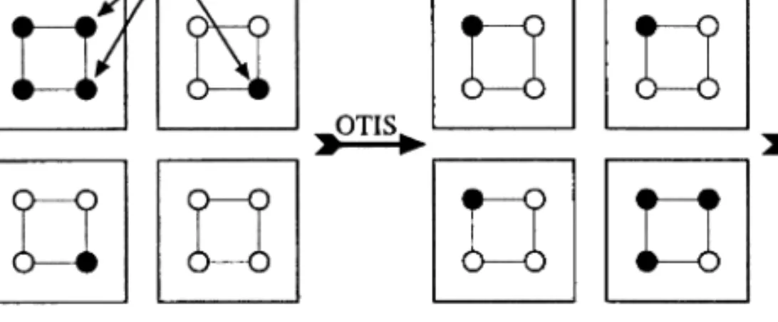
The OTIS-Mesh architecture consists of N groups, each of which is anN-node (i.e., -N_-N) 2D-mesh. For each PE of the OTIS-Mesh, interpret its address (g, p) as (gx, gy,px, py) by dividing the bits representing the group and position
into equal pieces. These values have natural interpretations as xy coordinates as shown in Fig. 3. OTIS then provides communication between groups, connecting nodes (gx, gy, px, py) and (px, py,gx, gy) for all 1px,py, gx, gy-N
We show that the OTIS-Mesh can simulate a 4D-mesh with the same number of nodes with small slowdown. Because of the stronger connectivity properties, the 4D-mesh can perform many operations, such as sorting or routing, significantly faster than the 2D-mesh. However, a VLSI layout of an N2node 4D-mesh requires
FIG. 3. OTIS-mesh.
0(N3
) area, so large-scale implementations suffer a substantial overhead to accom-modate all the wiring necessary. By contrast, the OTIS-Mesh with N2
nodes has layout area 3(N2).
(gx, gy, px, py) will represent the coordinates of the 4D-mesh in our simulation. With this interpretation, the mesh within the group g connects (gx, gy, px, py) to the four PEs (gx, gy, px\1,py) and (gx, gy, px, py\1), except at the boundaries. To simulate the 4D-Mesh, node (gx, gy, px, py) communicates with its four neighbors within the same group using the mesh connections within the group, realizing two dimensions of connectivity. The remaining two dimensions of connec-tions are simulated using OTIS. As an illustration, Fig. 4 shows how nodes which differ by one in gy can be connected in three steps using OTIS. Connections between nodes with different values ofgx are handled similarly.
Theorem 4.1. OTIS-Mesh can simulate a 4-dimensional (-N_-N_-N_
-N)mesh with a slowdown of at most a factor of 3.
Proof. Each of gx, gy, px, andpywill be a coordinate of the 4-D mesh address.
Using the mesh connections within each group as described above, we can simulate the two last dimensions of the 4-D mesh. To simulate communication across the remaining two dimensions, we will need three steps. First, send the data across the optical transpose links of OTIS. The information initially stored in PE (gx, gy, px,py) is now stored in PE (px, py, gx, gy). Then, using the mesh
connec-tions, this data can be moved to PE (px, py, gx\1, gy) or (px, py, gx, gy\1),
depending on the intended destination. Finally, use the optical transpose again, bringing the data to (gx\1,gy, px, py) or (gx, gy\1, px, py), which is precisely the desired connectivity. K
This simulation allows more efficient solutions to problems which have faster algorithms on higher dimensional meshes, like routing and sorting. However, it also can be viewed as a way to minimize wire lengths in large systems. By using a folded OTIS system, any two points on different chips can be connected with only wires across two chips. Using the same ideas as in the proof above, a signal is routed across the first chip to the location of the optical link to the destination chip. Then the signal is sent across the optical link and routed across the destination chip to the desired location. With this technique, a long off-chip line across a PCB or MCM is replaced by an optical link plus on-chip wires to route the signal from source to transmitter and from receiver to destination. Similar on-chip connections would also be required in the all-electrical case to reach the IO pads, however, so the additional overhead is minimal.
5. OTIS-HYPERCUBE
The hypercube or ncube is a versatile network for multiprocessor architectures. The hypercube architecture can simulate many other important topologies, such as meshes, meshes-of-trees, butterflies, and even PRAMs. Also many problems such as sorting and routing have efficient hypercube algorithms [14]. Several commercial machines, such as the CM-2, were based on implementations of the hypercube architecture. However, it is difficult to construct larger dimensional hypercubes using electronic technology. Since the degree of a node is logn, and not constant, the number of wires leaving each chip or group of chips must grow as the size of the network increases.
The OTIS-Hypercube consists of N groups, where each group is an N-node hypercube, connected via OTIS. This interconnection pattern is significantly sparser than that of a hypercube. Each node in an N2-node OTIS-Hypercube has degree (logN)+1: logNconnections to other nodes in its group and 1 optical link. Since anN-node hypercube has layout area3(N2), the OTIS-Hypercube has layout area O(N3). By contrast, an N2-node hypercube would have degree 2logN and require 0(N4) area for VLSI layout.
In a manner similar to the shuffle-exchange graph, OTIS can be used to simulate the connectivity of a full hypercube. The OTIS-Hypercube network is also closely related to the hierarchical cubic network (HCN) proposed by Ghose and Desai
FIG. 5. OTIS-hypercube routing.
[7]. The OTIS-Hypercube lacks the ``diameter'' links of the HCN, but this does not affect its ability to simulate the hypercube.
Let n=logN. Label the OTIS node (g, p) byg1} } }gnp1} } }pn, whereg1} } }gnis the binary representation ofgandp1} } }pnis the binary representation ofp. We will now show how to connect (g, p) to every node which differs from it in exactly one bit position.
If the bit position in question lies in the second half (i.e., the bits corresponding to the position within the group), then there is direct connection since all the processors (g,V) form a hypercube group.
If the bit position lies in the first half (i.e., the bits of the group address), then we first perform an optical transpose. This will interchange the bits of the group and the bits of the position. Now, the bit to be changed lies in the second half, so by the same argument as before, the nodes to be connected lie in the same group, and are thus linked by an electrical wire. Finally, another optical transpose restores the nodes to their original position. Figure 5 gives an example of this for a six-dimension hypercube, connecting two nodes which differ in the second bit.
More formally:
Theorem 5.1. An N2-node OTIS-Hypercube network can simulate an N2-node hypercube with a slowdown factor of at most 3.
Proof. Label the OTIS nodes by 2n-bit strings x1} } }x2n as above. The hyper-cube edges we wish to simulate are of the form:
x1} } }xi} } }x2nÄx1} } }xi} } }x2n
For i>n, these are the connections provided by the electrical hypercubes. For in, we use the routing path:
1. From x1} } }xi} } }x2n
3. to xn+1} } }x2nx1} } }xi} } }xnvia hypercube edges
4. to x1} } }xi} } }x2n via optical transpose. K
This factor of three slowdown in the proof is needed to ensure that the right ``parity'' is preserved; that is, that the group and position coordinates have returned to their original roles. In some problems, this is not necessary, and the simulation can run correspondingly faster. In particular, the optical transpose is necessary only when the communication switches between the low (1, ...,n) and the high (n+1, ..., 2n) dimensional edges of the hypercube. Thus, problems in which this happens seldom, like routing, can be done quite efficiently. For example, butterfly routing (subject to blocking) using an OTIS system with two processing planes experiences some additional latency (compared to routing on a full hypercube), but no additional loss of throughput, by the use of pipelining. The first logN coor-dinates are routed exactly as before. Then the optical transpose takes place (which is much simpler and faster than the routing stage), while a new set of inputs are sent to the first plane. The last logN coordinates are then routed on the second plane and output, while the new inputs are routed by the first plane and transposed. The technique can also be applied to algorithms which make more than one pass over the edges of the hypercube. For example, sorting using Batcher's sorting network [3] requires 1
2log
2Nsteps. However, only 2 logNswitches between high-and low-dimensional edges are required, so the overhead in simulating this algo-rithm on and OTIS-Hypercube is relatively small. Finally, using known network emulations (see [14] for details), such a network can be used to simulate meshes of any even dimension, meshes-of-trees, and butterflies.
6. OTIS-EXPANDER
In this section, we demonstrate how to construct large random-like graphs called expanders in a scalable fashion using OTIS. While it may seem counterintuitive that random or near-random wiring could be helpful, there are several results which demonstrate that randomness or expander graphs are useful in many types of rout-ing or sortrout-ing problems. For example, Valiant and Brebner [24] demonstrated that choosing random intermediate destinations prevent worst-case behavior in butterfly routing. Instead of using randomness on-line, results involving expanders utilize the random-like connections of the network to obtain good worst-case performance from deterministic routing algorithms as well as robustness in the presence of faults. Unlike the mesh and the hypercube, expander graphs are not an explicit set of connections. Rather, they refer to any graph with constant degree at most dwhich has the property that for any set of nodes S with |S| :N, the neighborhood ofS has size at least c|S|, for some constant c>1. We will use the notation (N,:, c)-expander to denote such a graph. The constant-degree restriction is intended to capture some notion of efficiency; without it, the complete graph on graph on N nodes would be an (N,:, 1:)-expander. While there are explicit constructions of graphs of this kind, the graphs with the strongest form of this property (i.e., large values of c) are constructed by choosing graphs at random. (For a simple proof which shows that a randomly chosend-regular graph is likely to have this property,
see Section 5.3 of [18].) For large enough values ofN, one can show that a random choice ofGis likely to havecclose tod, for values of: satisfying c:<1.
However, circuits which provide the connectivity of expander graphs are quite difficult to produce. While explicit constructions of expander graphs are known, they produce small values ofcrelative tod, which limits their usefulness. As men-tioned above, random graphs are likely to have good expansion properties. However, if we attempt to partition a large random graph across many chips, we expect that nearly every edge of the graph will connect nodes on different chips. As the size of the required expander becomes larger, each chip requires more pins. In addition, the definition of expansion implies that an expander graph onN2 nodes must have bisection width 3(N2) and thus require layout area 0(N4).
A natural goal is to address this problem by producing an expander which can be partitioned into smaller pieces with manageable communications between the pieces. Graphs of this type, referred to as hierarchical expanders, were first con-sidered in [4]. There, the authors show how one can build large expander graphs without increasing the number of different wires required. Essentially, each chip or module has a small number of cables, and each cable is made ``thicker'' as the number of nodes is increased. Here, however, the optical transpose provides wires from every group of nodes to every other group of nodes without the explosion in wiring complexity that the construction in [4] sought to avoid. At the same time, that construction relies on many different, independent random choices of wiring. For the systems of boards connected by cables that the authors envisioned, this can be accomplished simply by connecting cables to boards in a random fashion. However, at the finer scale of parallelism we envision, this would require the fabrication of many different chips, each with its own random wiring, greatly increasing the cost of such a system. Here, we construct a hierarchical expander which allows large expanders to be constructed using many copies of the same randomly wired chip. Then, in the next section, we will use this technique to construct other networks, called multibutterflies, for which many applications are known.
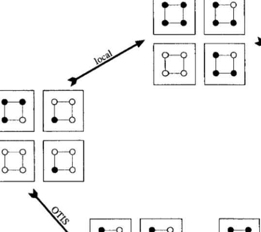
The OTIS-Expander is constructed from N identical copies of a fixed (N,:,c) expander, which are connected to one another using the transpose connections of OTIS. We show that this OTIS-Expander can simulate an expander by showing that for any small set of nodesS,Scan reach a large set of nodes within two steps: either by simply taking local connections, or by taking the OTIS connection and then following local connections. Note that the OTIS-Expander is not itself an expander; ifSis the set of all nodes in the first group, its neighborhood is no larger. However, in this case, following the OTIS connections disperses the nodes across the groups, and then local connections allow the set to expand.
These two paths are depicted in Fig. 6. Our goal will be to show that for any initial setS, the set which results by combining the nodes reachable by either these two paths is large, as shown on the right-hand side of the figure.
Theorem 6.1. Let G be an N2 OTIS-Expander constructed from N copies of an
(N,:,c) expander. Then G can simulate an (N2,:2,c2) expander with a slowdown of a factor of two.
FIG. 6. OTIS-expander routing.
Proof. To show that a graph has expansion, we need to show that any suf-ficiently small set of nodes expands to a much larger set by following the edges of the graph. The intuition behind this theorem is that expansion will occur as long as the sets involved are not too large, and that the sets before and after the optical transpose cannot both be large.
Let S be a set of nodes of size at most :2
N2
. We will divide the nodes into two classes: those which begin in ``large'' groups, (groups with more than:Nelements of S) and those which begin in ``small'' groups (groups with at most :N such elements). Since every node is in exactly one of these categories, one category
FIG. 8. OTIS-expander: Large groups case.
contains at least half the nodes inS. The proof considers these two cases, illustrated in Figs. 7 and 8, individually.
If the small groups have more nodes, ignore all nodes in large groups. By doing so, we only decrease the size of the set of neighbors of S and underestimate the expansion of the graph, because the size of the neighborhood ofS is a monotonic function of the nodes of S. Consider the nodes of S group by group, and let Si
denote the number of nodes ofSin groupi, not counting the nodes in large groups that we ignored. Because we only consider nodes in small groups, for all i, |Si| is
at most:N. Therefore, the neighborhood of eachSihas size at least c|Si|, and the
neighborhood of S has size at least c |Si|. Since at least half of the nodes in S
were in small groups, |Si| |S|2. This implies that the neighborhood of S has
size at leastc|S|2, and thus the graph has expansion at leastc2.
If the large groups have more nodes, ignore all nodes in small groups. There are at most :N large groups, because each group we did not ignore has at least :N
nodes ofS, and Shas size at most :2N2
. From each such node, follow the optical link. The OTIS connections provide only one link between each pair of groups, so each group can only receive at most one node from each other group. However, since before the transpose there were at most:N groups containing nodes, during the transpose each group receives at most one node from each nonempty group, or at most:Nnodes. Then, we can use a similar argument to the one used in the small groups case above: each groups has at most :N nodes, so within each group, the neighborhood is larger by a factor of at leastc. Since the number of nodes we did not ignore is at least |S|2, the size of the neighborhood across all the groups has size at leastc|S|2, and the graph has expansion at least c2. K
7. SCALABLE MULTIBUTTERFLY CONSTRUCTION
While expanders have many useful properties, their unstructured nature makes designing algorithms for them difficult. More practical work on using expanders for routing has centered on the multibutterflynetwork, which uses expanders as com-ponents in a more structured network. In a standard butterfly network, the each bit of the destination address is used to divide the packets into two classes, and so each
FIG. 9. Multibutterfly network.
node has an up wire and a down wire to nodes in the next stage corresponding to these two possibilities. These connections are made in a regular fashion: at theith stage nodex1} } }xnis connected to the same node of the next stage as well as node x1} } }xi} } }xn. In a multibutterfly, the address bits are used to partition packets into two classes, and each node has wires to each class in the next stage. However, each node will have several such connections, and they will not form a regular pattern as in the butterfly. A single stage of a butterfly network and a correspond-ing stage of a multibutterfly network are shown in Fig. 9. At level i, the nodes can be naturally divided into 2i partitions based on the address bits followed to that point. In a multibutterfly, the bipartite graphs formed between each partition and either of the partitions connected to it in the next level are expander graphs. Bipar-tite graphs with this property are called splitters because of their applications to routing. This two-way expansion property guarantees that in order to cause a few nodes at level ito be blocked, many nodes at level i+1 would need to be blocked. By using this reasoning level-by-level, one can show that it is difficult to cause the inputs to become blocked, even in the presence of faults.
For many important routing problems, efficient solutions on the multibutterfly network are known (see [16] for a survey). For example, on anNinput multibut-terfly, deterministic algorithms are known for packet-routing [23] and circuit switching [1] which takeO(logN) steps (previous results required the use of ran-domness or the complicated AKS sorting circuit mentioned in the previous section). In addition, if k switches fail, this routing can still be accomplished between
N&O(k) inputs and outputs [15].
As in the case of the expander, our goal will be to construct a network with ran-dom-like connections efficiently. To do so, we use a construction similar to that of the OTIS-Expander. Here we describe the construction of the first stage, later stages use similar designs on smaller scales. As in the OTIS-Expander, each group is a copy of a single expander graph. However, each group will have Ninputs, N2 up outputs, andN2 down outputs. The connections between the inputs and the out-puts form a splitter; that is, any setSof at most:N inputs is connected to at least
c|S| up outputs andc|S| down outputs. We refer to such a graph as an (N,:,c 2)-splitter. Obviously, this implies thatc:must be smaller than 1
2. The OTIS connec-tions will be used to connect the input nodes of different groups, rather than to
FIG. 10. OTIS-multibutterfly routing.
connect input nodes to output nodes. That is, thepth input of thegth group is con-nected to the gth input of the pth group via OTIS.
In order to show that this network can simulate a multibutterfly, it is necessary to show that any small set Sof input nodes is connected to at least c$ |S| output nodes, for some constantc$>1. The simulation of a stage of the multibutterfly will require three steps. In the first step, each input node communicates with every out-put node to which it is connected and also to the node to which it is connected by the OTIS transpose link. In the second step, every input which received a message from the optical link in step one communicates that message to the outputs to which it is connected. These two steps mirror the method used in the OTIS-Expander simulation. Finally, in the third step, the packets at the output nodes are sent via OTIS connections to the next stage. Figure 10 shows a sketch of this simulation in the context of a multibutterfly stage.
Theorem 7.1. Let G be an OTIS-Expander constructed from N copies of an
(N,:,c)-splitter.Then G can simulate an (N2 ,:2
,c2)-splitter with a slowdown of a factor of three.
Proof. The same argument which showed that the OTIS-Expander has expan-sion will show that both the up and down edges have expanexpan-sion, or equivalently, that the graph is a splitter. Since in either stage, packets with different destinations never contend for the same edge, we consider only the packets traveling upward. We then show that for any setSof inputs nodes which begin with packets traveling upward. As in the OTIS-Expander proof, we examine two cases, depending on the initial distribution of packets or input nodes.
In the first case, the majority of these packets are in groups with less than :N other packets traveling upward. Ignoring the groups with more than :N packets, the number of nodes in each group expands by a factor of cduring the first stage, as the inputs communicate with the outputs via the expander connections. Since at least half of the numbers were in small groups, this demonstrates expansion c2.
TABLE 2
Layout Area Comparison, N2Nodes
Layout Area Slowdown
4D-mesh 3(N3) 1 OTIS-mesh 3(N2) 3 Hypercube 3(N4) 1 OTIS-hypercube 3(N3) 3 Expander 3(N4) 1 OTIS-expander 3(N3) 2
In the second case, the majority of these packets are in groups with at least :N such packets. We ignore the nodes in groups with less than:Npackets. Each group will receive at most one packet from each other group while communicating across the OTIS transpose edges. Thus, at the beginning of stage two, each group will have at most :Npackets that have neither been ignored or been transmitted to the outputs. This ensures that during stage two, each group will expand by a factor of cas it communicates with the outputs. Since we ignored at most half of the packets initially, this implies that graph has expansion at leastc2.
At this point, packets traveling upward have gone through some expander edge and have now been sent to some of the first N2 outputs of some groups. Likewise, packets traveling downward have been sent to the lastN2 outputs of each group. Now, we use the OTIS connections once more, this time to connect the outputs of the different groups together rather than the inputs. Passing the data though these OTIS connections on the output nodes, packets traveling upward reach the nodes in groups 1 through N2, while packets traveling downward finish in groups N2+1 through N. K
At the end of the first stage, the nodes traveling up are sent to one set of groups, and the nodes traveling down are sent to a different set of groups. To construct a complete multibutterfly, the same construction would then be applied separately to each of these sets of groups, continuing in a recursive fashion until each set contains only one group. At this point, no communication between different chips is necessary, and a single-chip multibutterfly can be used to perform the routing in the final stages.
8. CONCLUSION
The Optical Transpose Interconnection System provides an efficient means of providing a particular set global interconnections using optical communications. The use of free-space optics allows efficient, high-density, high-speed long distance communication. Using these interconnections, small groups with only local connec-tions can simulate networks with powerful global connectivity. The OTIS-Mesh connects groups with 2-D mesh topology into a 4-D mesh. This technique can also be used to reduce wire lengths in large systems. By connecting groups with hyper-cube topologies with OTIS, one produces the OTIS-Hyperhyper-cube, which is capable of
simulating a hypercube connecting all nodes in all groups with fewer wires. Using this result, many popular networks like meshes, meshes of trees, and butterflies can be simulated. Finally, this technique allows large expander graphs to be constructed in a scalable fashion by connecting many copies of a small expander into the OTIS-Expander network. The same techniques used to construct these scalable expanders can be used to construct large splitter graphs, for use in multibutterfly routing networks. In each case, the addition of the optical connections allows for a significantly more area-efficient layout, as summarized in Table 2.
REFERENCES
1. S. Arora, F. T. Leighton, and B. Maggs, On-line algorithms for path selection in a non-blocking network,in``Proceedings of the 22nd Annual ACM Symposium on the Theory of Computing,'' May 1990, pp. 149158.
2. M. Ajtai, J. Komlos, and E. Szemeredi, Sorting in clognparallel steps, Combinatorica 3(1983), 119.
3. K. Batcher, Sorting networks and their applications, in``Proceedings of the AFIPS Spring Joint Conference,'' Vol. 32, 1968, pp. 307314.
4. E. Brewer, F. T. Chong, and F. T. Leighton, Scalable expanders: exploiting hierarchical random wir-ing, in ``Proceedings of the 26th Annual ACM Symposium on the Theory of Computing,'' Montreal, Quebec, May 1994, pp. 144152.
5. S. Esener, P. Marchand, F. Kiamilev, V. Ozguz, and Y. Liu, Optical interconnects of stacked silicon chips, in ``INTERpack'99, The PACIFIC RIMASME International, Intersociety Electronic and Photonic Packaging Conference,'' Lahaina, HI, June 1319, 1999.
6. M. Feldman, S. Esener, C. Guest, and S. Lee, Comparison between electrical and free-space optical interconnects based on power and speed considerations,Appl.Opt.27, 9 (May 1988), 17421751. 7. K. Ghose and K. R. Desai, Hierarchical cubic networks, IEEE Trans.Parallel Distrib.Syst.6, 4
(Apr. 1995), 427435.
8. W. Hendrick, O. Kibar, P. Marchand, C. Fan, D. Van Blerkom, F. McCormick, I. Cokgor, M. Hansen, and S. Esener, ``Modeling and Optimization of the Optical Transpose Interconnection System,'' Optoelectronic Technology Center, Program Review, Cornell University, Sept. 1995. 9. S. Hinterlong, ``High Performance SEED-Based Optical Computing Systems,'' 1995 ARPA MTO
Program Review, Big Sky, Montana, July 1995.
10. H. Hinton, ``An Introduction to Photonic Switching Fabrics,'' Plenum, New York, 1993.
11. F. Kiamilev, P. Marchand, A. Krishnamoorthy, S. Esener, and S. Lee, Performance comparison between optoelectronic and VLSI multistage interconnection networks,J.Lightwave Technol.9, 12 (Dec. 1991), 16741692.
12. O. Kibar, P. Marchand, and S. Esener, High-speed CMOS switch designs for free-space optoelectronic MINs,IEEE Trans.VLSI Syst.6(Sept. 1998), 372386.
13. A. Krishnamoorthy, P. Marchand, F. Kiamilev, and S. Esener, Grain-size considerations for optoelectronic multistage interconnection networks,Appl.Opt.31, 26 (Sept. 1992), 54805507. 14. F. T. Leighton, ``Introduction to Parallel Algorithms and Architectures,'' Morgan Kaufmann, San
Mateo, 1992.
15. F. T. Leighton, and B. Maggs, Expanders might be practical: Fast algorithms for routing around faults on multibutterflies and randomly-wired splitter networks, IEEE Trans.Comput.41, 5 (May 1992), 110.
16. F. T. Leighton, and B. Maggs, The role of randomness in the design of interconnection networks, in``Algorithms, Software, Architecture'' (J. van Leeuwen, Ed.), ``Information Processing 92,'' Vol. I, pp. 291305, Elsevier, Amsterdam, 1992.
17. G. Marsden, P. Marchand, P. Harvey, and S. Esener, Optical transpose interconnection system architectures,Opt.Lett.18, 13 (July 1993), 10831085.
18. R. Motwani and P. Raghavan, ``Randomized Algorithms,'' Cambridge Univ. Press, Cambridge, UK, 1995.
19. S. Rajasekaran and S. Sahni, Randomized routing, selection, and sorting on the OTIS-Mesh, IEEE Trans.Parallel Distrib.Syst.9, 3 (Sept. 1998), 833840.
20. S. Sahni and C.-F. Wang, BPC permutations on the OTIS-Hypercube optoelectronic computer, Informatica22, 3 (Oct 1998), 263269.
21. C. A. Thompson, Area-time complexity for VLSI,in ``Proceedings of the Eleventh Annual ACM Symposium on Theory of Computing,'' May 1979, pp. 8188.
22. C. A. Thompson, ``Complexity Theory of VLSI,'' Ph.D. thesis, Department of Computer Science, Carnegie-Mellon University, Pittsburgh, PA, 1980.
23. E. Upfal, AnO(logN) deterministic packet routing scheme, in ``Proceedings of the 21st Annual ACM Symposium on Theory of Computing,'' Seattle, WA, May 1989, pp. 241250.
24. L. Valiant and G. Brebner, Universal schemes for parallel communication, in ``Proceedings of the 13th Annual ACM Symposium on Theory of Computation,'' Milwaukee, WI, May 1981, pp. 263277.
25. C.-F. Wang and S. Sahni, Basic operations on the OTIS-Mesh optoelectronic computer, IEEE Trans.Parallel Distrib.Syst.9, 12 (Dec. 1998), 122636.
26. X. Zheng, P. Marchand, D. Huang, N. Ozkan, O. Kibar, and S. Esener, Design and packaging of a scalable vertical free-space optoelectronic interconnection system,Appl.Opt., to appear. 27. X. Zheng, P. Marchand, D. Huang, and S. Esener, High speed parallel multi-chip interconnection