Embedded Component Infrastructures
Markus Voelter1, Christian Salzmann2, and Michael Kircher3 1
Voelter - Ingenieurb¨uro f¨ur Softwaretechnologie Heidenheim, Germany [email protected]
2
BMW Car IT, M¨unchen, Germany [email protected] 3 Siemens AG Corporate Technology, M¨unchen, Germany
Abstract. In this chapter we motivate the need for an infrastructure platform
for embedded software, supporting the development of reusable systems. Our solution is based on a component infrastructure that is implemented using model-driven software development (MDSD) techniques. This approach allows us to achieve the goal of re-usability while still providing an efficient system, tailored for the specific embedded hardware and operating system.
This chapter explains the principles of our approach and introduces model-driven software development. It illustrates the concepts by presenting an example of how to model and specify the embedded application (a simple weather station), and how to generate supporting component middleware infrastructure from these models.
1
Introduction
Development of embedded software is one of the most challenging fields in software en-gineering today. Since innovations in many industries traditionally grounded in mechan-ical engineering (such as automotive or aerospace) shift more and more from mechani-cal solutions to electronic and computerized functions, embedded software emerges as one of the most promising application domains for software engineering. In the auto-motive industry for example, over the last years 90 percent of all innovations in new models were driven by electronics. As a consequence of increasing the amount of elec-tronic functions, software emerges as a central aspect in a car. In current premium cars we face a total amount of up to 270 functions the user interacts with, deployed over 67 independent embedded devices (ECU - Electronic Control Unit). All in all, this sums up to about 65 megabytes of binary code.
Classical embedded software applications used to be isolated: small programs that typically run on a single embedded device. Usually, the amount of code used to be in the area of some kilobytes per device. Abstractions were minimal and the focus was on efficient resource consumption and optimized performance, getting the most of the available hardware. As a consequence, typical platforms were minimal with respect to the provided services, and applications were programmed directly in machine code or in rather low-level languages such as C.
However, the amount, nature and complexity of embedded software changes rapidly. Today, we are faced with networks of embedded devices where devices interact with other embedded devices via various networks and bus systems. Considering cars again, it is expected that we will reach the amount of one gigabyte of binary code within the next six years, distributed via a network of several buses and about 70 devices. The complexity of such a system is comparable to a state of the art desktop workstation of today. It seems obvious that a system of that size cannot be developed with the meth-ods and abstractions of classical embedded software. But a workstation and its software faces completely different needs compared to software in embedded devices, such as in cars: the product lifetime of embedded software is substantially longer than the aver-age 3 years of an office product (with its several hot fixes), the strong time-to market-pressure of an office feature vs. the demands for reliability of embedded software etc. We therefore need similar levels of abstraction as we learned from the desktop and en-terprise world, however, these must cope with the additional challenges of reliability, flexibility and performance faced in the embedded domain.
The challenge. Why is it so much harder (roughly a factor of 20) to develop the same
piece of functionality in an embedded ECU in the automotive domain compared to the same functionality developed for the traditional IT world or for a device with similar characteristics, say a Pocket PC PDA? One reason for this is that embedded software is more or less developed from scratch for each application. There is only very little reuse, compared to desktop software. We can identify a set of key requirements for the reuse to be practical:
– Resource optimization: due to unit based cost structure, modularity must not be
overly expensive with respect to resources consumption such as memory or CPU allocation.
– Adaptable to different domains: although software modules may be developed in
different ways due to the heterogeneity of the various domains in a vehicle (e.g. brake system vs. infotainment) it must be possible to assemble them to one system.
– Customizable to specific hardware but also transferable from one hardware
plat-form to another: due to the life-cycle gap and the hardware/software correlation the software must be transferable from old hardware platforms to newer ones, but still optimized with regards the hardware.
– Extensible: as another consequence of the life-cycle gap, it must be possible to
extend a software system during its lifetime and upgrade it with new features. The overall goal in today’s embedded software development is to reduce complexity of the system, to save development effort (and thus, cost) and to achieve a shorter time to market, while taking account the above requirements.
In the course of our research of how to address the above mentioned requirements, we analyzed existing development methodologies and technologies that have success-fully been used in the development of business and enterprise applications in the past. Here we focused on the separations of concerns on programming level and on modeling level (through middleware).
Re-usability through separation of concerns. Separation of concerns [16] and
asso-ciated modularization of functionality has successfully helped large applications to be developed quickly and efficiently. Here is a brief overview.
– Object-orientation (OO) separates different functionalities into modules called
classes. But OO left the separation of non-functional, operational [7] requirements untouched.
– Frameworks also encapsulate concerns architecturally and are therefore fairly
static.
– Component/Container infrastructures [22] such as EJB [18], COM+ [5], CCM [13]
or (to some extent) OSGi [15] go one step further. Their goal was to isolate applica-tion funcapplica-tionality from technical, operaapplica-tional funcapplica-tionalities, by encapsulating the application functionality into components, the operational functionalities into con-tainers - decoupling them via well defined interfaces. The separation of concerns is done architecturally.
– Aspect-oriented Software Development (AOSD) focuses on weaving encapsulated
aspects into the existing application code. Specialized languages have been devel-oped to connect aspect code with the locations where the aspects are to be applied. Today, AOSD tools showcase interesting ideas, but do not provide industry-proven solutions [17], yet.
Middleware. Having done a proper separation of concerns and having achieved a
cer-tain level of modularization, it becomes important to provide a run-time environment for the individual application components. For this glue code, the term middleware is typically used. The glue code addresses those concerns that have been factored out of the application components. If the application components have to run in a distributed environment, connected through networks and buses, it becomes important that the mid-dleware also covers remote communication transparently. For the purpose of this chap-ter we focus on communication middleware as one of the most prominent examples of middleware.
CORBA is one of the most widely used middleware standards, but its implementa-tions are often to large (wrt. memory footprint) for embedded applicaimplementa-tions. Therefore, the Minimum CORBA [11] standard was defined, which defines a subset of the highly configurable CORBA features. But Minimum CORBA is still too large for many sce-narios and causes too much run-time overhead for embedded systems.
Where quality of service (QoS) properties, latency and delay of remote invoca-tions play an important role, Real-time CORBA [12] becomes interesting. Real-time-CORBA aims at addressing the management of QoS properties between clients and servers end-to-end.
To make the footprint sufficiently small and the execution overhead sufficiently low, actual implementations of Minimum and Real-time CORBA have defined their own “customized” set of features for the embedded domain (independent of any OMG spec-ification). Some implementations are quite small; their footprint is sometimes 100 kB, or even less. Nevertheless, with their restricted functionality, they are limited, but suffi-cient for many use cases.
Middleware implementations, such as CORBA, use code generation for their adap-tation layers. The generated code connects applications clients and remote object im-plementations with the underlying communication middleware.
From a structural view, communication middleware typically consists of a frame-work [19] and adaptation layers. While the frameframe-work provides the core functionality, the adaptation layers mediate between clients, the core, and the remote objects. The adaptation layer is typically code generated, as it is specific to the remote objects inter-face.
For some stringent embedded environments, even the optimized frameworks and the generated code are too rigid in size and QoS. One of the reasons is that the remote objects, their dependencies, and their deployment is typically only considered from the viewpoint of individual remote objects, not from a system view. This, however, is necessary to further minimize resource consumption.
2
Description of Our Approach
Our proposed approach to building embedded component infrastructures is based on the combination of Component/Container infrastructures (including the underlying com-munication middleware) with model-driven software development techniques.
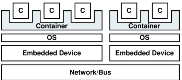
Component/Container infrastructures unify various middleware approaches, specif-ically, separation of technical and functional concerns as well as remote communication and QoS management (see [22]). While of course we use code generation, in contrast to many other code generation approaches used in embedded systems, we do not gener-ate any application logic. Rather, we focus on the generation of the infrastructure code required to make the application logic work in the context of the embedded system’s hardware infrastructure. Using the terminology of the components/container approach, we generate the container, not the components. As explained in the previous section, this is essential to come up with a minimum-overhead implementation of the infras-tructure. The next illustration shows the basic architecture.
Embedded Device Embedded Device
Network/Bus C C C Container C C Container OS OS
Fig. 1. Layered architecture of an embedded container infrastructure
The functionality of an embedded application is encapsulated in components (the C’s in Fig. 1). The functionality is accessed using interfaces; the component accesses its
environment using interfaces, too. The application logic is supplied using implementa-tion files (e.g. C files) that have to stick to certain convenimplementa-tions, as explained below. The component implementation is developed manually. Here, ”developed manually” means that the creation process is outside the scope of the generative process introduced in the next section. It is of course possible to use tools such as Ascet, Statemate, etc. to generate the implementation.
As mentioned before, the containers, which constitute the middleware part of the system, are code generated. In order to be able to generate this code, we need vari-ous specifications (or models) that drive code generation. These models capture aspects such as component types, interfaces, connectors among components, hardware topol-ogy, network types, QoS constraints etc. The specifics of the models depend on the domain for which we want to generate containers.
From these models, the generator tool generates all the infrastructure code required to make the application logic work in the embedded environment. This might include interrupt handling, scheduling, network/bus access and timing constraint verification. Before the generator actually generates code, it will verify the model’s compliance to the rules specified by the component/container meta-model, as well as the the con-straints implied by the specific embedded environment, in which the system is intended to run.
The approach just outlined is known as model-driven software development, or MDSD. The next section explains some details of the model-driven software devel-opment paradigm in general, including modeling and meta-modeling, definition of domain-specific languages, generator tools and platform design.
2.1 Model-Driven Software Development
Model-driven software development (see [20]) is about making models first class de-velopment artifact as opposed to ”just pictures”. Various aspects of a system are not programmed manually; rather they are specified using a suitable modeling language. These models are significantly more abstract than the implementation code that would have to be developed manually otherwise - they are specific to the domain for which the models are relevant. The modeling languages used to describe such models are called domain-specific languages (DSL).
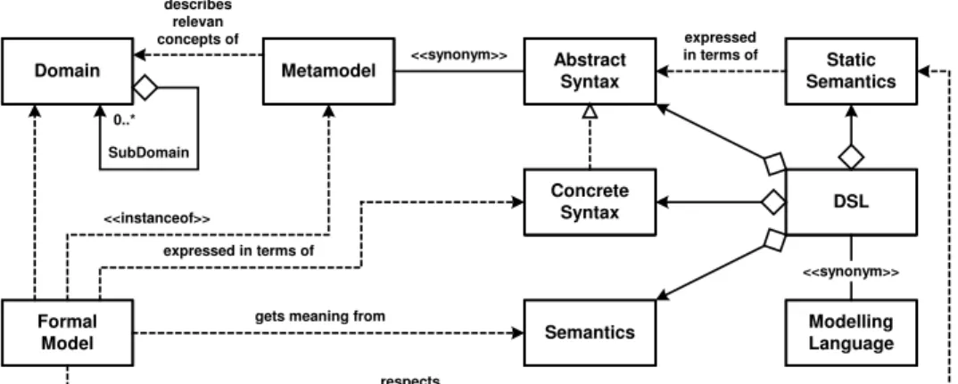
Domain specific languages. Like any other (formal) language, a DSL has three
con-stituent parts:
– A meta-model (also called abstract syntax) defines the building blocks of the
lan-guage, and the rules how they might be combined to form legal models (sentences in the DSL)
– A concrete syntax defines the actual notation used to specify models (or sentences).
A particular meta-model might have several concrete syntaxes; concrete syntax can be textual (in which case sentences are often called specifications) or graphical (where sentences are often termed models). We use both terms interchangeably.
– Finally, a DSLs needs to have semantics; the meaning of models has to be
Models themselves are not useful in the final application. Rather, models have to be translated into executable code for a specific platform. Such a translation is imple-mented using model transformations. A model is transformed into another, typically more specific (less abstract) model; a series of such transformations results in exe-cutable code, since the last transformation is a model-to-code transformation. Because of today’s somewhat limited tool support, many MDSD infrastructures use just one generation step, directly from the models to code. Model transformation tools using the latter approach are often referred to simply as model-driven code generators. Figure 2 shows the most important concepts as a UML model.
Domain Metamodel <<synonym>> AbstractSyntax SemanticsStatic describes relevan concepts of Formal Model 0..* SubDomain <<instanceof>> Concrete Syntax expressed in terms of Semantics gets meaning from
expressed in terms of DSL respects Modelling Language <<synonym>>
Fig. 2. Core concepts of DSLs
Semantics. In addition to producing less abstract models (or implementation code),
model transformations also serve the purpose of defining the semantics of the model they transform. By describing the rules of how a model is projected onto an implemen-tation language, the meaning of the model is defined. Although this is a rather pragmatic approach of defining semantics, it works well in practice. This definition of semantics has the disadvantage that we cannot formally ensure that, if we have several sets of transformations which transform the models to different target languages (with well-known semantics), the defined semantics are the same. In practice we can use testing to make sure they are the same, but there is no formal way to ensure it.
Complex systems typically consist of a variety of concerns, such as components and their interfaces, the description of the deployment infrastructure (hardware) or timing and concurrency concerns. It is often not practical to use a single modeling language for all of these aspects; specifically, different concrete syntaxes are often useful. For example, the components and interfaces can be described using (stereotyped) UML, the hardware and the deployment using XML, and dynamic and concurrency aspects
using a specific textual language. The generator must be able to understand all of these, and integrate the different partial models into a coherent whole. Note that some aspects of an application - typically the application logic - might be sensibly described using a 3GL programming language. It is perfectly ok to use a 3GL, nobody should feel forced to ”invent” a DSL if the general purpose programming language is efficient for the particular task at hand.
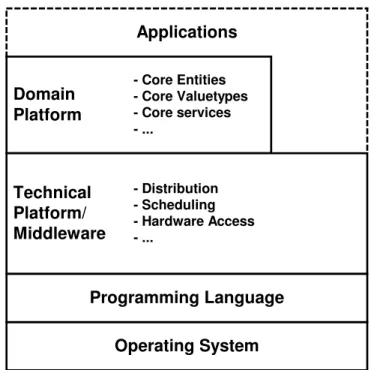
Platforms. While code generation is a powerful tool, it usually does not make sense
to generate the complete code - the complete middleware infrastructure in our context. Just as today, where nobody would re-implement printf, programmers will almost al-ways rely on a set of libraries, frameworks and pre-built components for application development. In the embedded world, performance considerations might limit the ap-plicability of this approach, but this depends on specific constraints. Together with the operating system and the base libraries provided by the programming language, all this is referred to a the platform. Figure 3 shows the layering structure of a typical applica-tion architecture.
Domain
Platform
Technical
Platform/
Middleware
Operating System
Programming Language
- Distribution - Scheduling - Hardware Access - ... - Core Entities - Core Valuetypes - Core services - ...Applications
Fig. 3. Layered structure of a domain-specific platform
Restating the role of model transformations, they map the (platform-independent) application model to code that runs on and utilizes the target platform. By providing a set of transformations, it is possible to generate implementations for several platforms.
It is theoretically possible to generate any of the layers in Fig. 3. However, in the context of component/container infrastructures in embedded systems, the following approach has proven to be most useful in practice:
– Obviously, the programming language and its base libraries are not generated. – The operating system is not generated either, although it is usually configured
(tai-lored) based on the model. Configuration files are generated.
– The primary candidate for generation in our context is the technical
plat-form/middleware layer.
– The domain platform is usually supplied in the form of reusable, pre-built software
components.
– Finally, components are implemented manually. Applications are implemented as
a set of collaborating components.
To restate; The goal of our approach is to generate the technical platform, or middle-ware, on which applications can run. Using code generation we can combine the ad-vantages of modularization, separation of concerns, and reuse with efficient implemen-tation. We will show in the example below, how this is achieved.
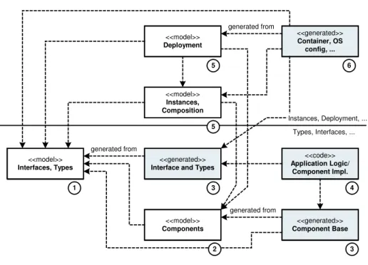
Design Flow. This subsection briefly describes the design flow that is typically used
in embedded component projects. The UML-like diagram in Fig. 4 shows the issues; below we explain the steps.
<<model>>
Interfaces, Types Interface and Types<<generated>>
generated from
<<model>>
Components Component Base<<generated>>
generated from <<code>> Application Logic/ Component Impl. 1 3 2 3 4 <<model>> Instances, Composition <<model>> Deployment 5 <<generated>> Container, OS config, ... generated from 6 5 Types, Interfaces, ... Instances, Deployment, ...
In the first step, we define interfaces and complex types. Since an interface can be used by various components, it is crucial to define them first, independent of compo-nents. In a second step, we define components and their communication ports. Here, we also define some of the communication parameters; for example, whether the communi-cation in a port should happen synchronously or asynchronously. Since this affects the API against which the implementation code is developed, these definitions have to be made before the application logic is implemented (manually) in step four. Before doing this, we generate these interface APIs as well as component base code (for example, base classes in OO, wrappers in C), see step 3. This concludes the component definition phase.
In step five we define which component instances we will use, how their ports will be connected; and on which hardware devices these instances will be deployed, as well as other system constraints. All these models together will then be used by the second generation step that creates all the infrastructure code: the container, the communication implementations, OS configuration files, build scripts, etc. In a final step (not shown) all the generated code we be compiled and linked using the generated build script, resulting in the final system.
Software system families. Using a model-driven software development approach
usu-ally pays off only in the context of software system families. The various members (or products) of such a family have a number of features in common, allowing sys-tematic reuse. Specifically, the DSLs used to describe the members of the family are usually the same. In order to come up with a suitable DSL, transformer/generator and platform (together called the domain architecture) the developers need to have a good understanding of the domain for which they develop the infrastructure. Domain anal-ysis techniques can help to deepen this understanding. In practice, developing useful domain architecture happens incrementally and iteratively over a relatively long time -based on experience.
Architecture. Software architecture plays an important role in the context of
model-driven software development. Transformations rely on the availability of a well-defined meta model for the source as well as the target. They are literally rules describing how to map the concepts from the source meta model to the concepts provided by the target meta model. In order for transformations to not be overly complex, the concepts defined by the meta models must be concise, precise and limited in number. With regards to the final transformation step (the one that produces implementation code) this means, that the architecture of the target platform, as well as the mapping of application concepts to this platform needs to be clearly defined.
3
Example: A Simple Weather Station
Overview. This section aims at illustrating our approach with a more concrete example.
We use a small distributed weather station for the purposes of the example. The weather station consists of several nodes (micro controller) connected by a bus, on each of these nodes software components will be deployed.
Main Node Outside Node Inside Node Bus Bus Inside Building Outside of Building Readouts Temp .
Sensor Hum.Sensor Temp .
Sensor Hum.Sensor
Fig. 5. Weather station example scenario
The example consists of three nodes, one outside node, the main node and an inside node, connected by a Bus (for example CAN). In the course of this example, we will take a look at the following artifacts:
– The models necessary to describe a weather station,
– The tool chain necessary to validate the models and generate the code, and – How code generation works in detail.
Models. We use three different models to describe the distributed embedded system of
the weather station:
– A type model describes interfaces, components and their ports,
– A composition model describes component instances and how they are connected,
and
– A deployment model describes the physical infrastructure and how component
in-stances and connectors are map onto it.
Interfaces are specified with a textual DSL, similar to CORBA IDL. The following example defines the Sensor interface to have three operations start, stop and measure. The controller interface has a single operation reportProblem which sensors will use to report problems with the measurement.
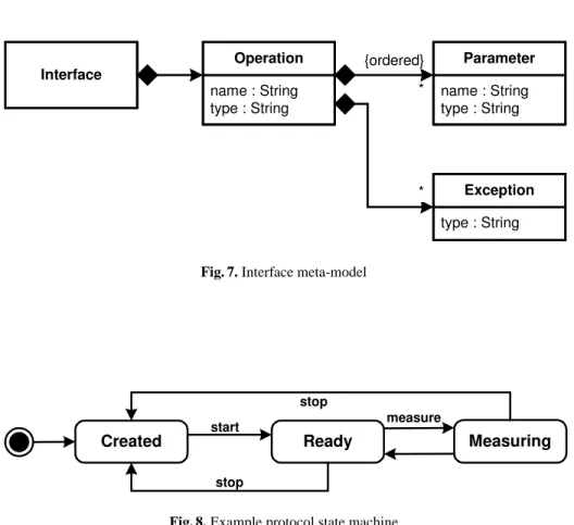
Instead of a textual model as shown above, we could also use a graphical model, as long as the same information is conveyed. The information included in an inter-face definition is described using a meta-model. As explained above, the meta-model describes the constructs a DSL provides for building models. The meta-model for inter-face definitions is given below. As one would expect, the meta-model defines interinter-faces as artifacts that own a number of operations which each have a name, a return type as well as a number of parameters (each with a name and a type) as well as exceptions.
The next step in describing a component-based system is the component model. We use a graphical notation for this aspect of the overall model, which uses UML syntax
interface Sensor { operation start():void; operation stop():void; operation measure():float; } interface Controller { operation reportProblem(Sensor s, String errorDesc ):void;
}
Fig. 6. Example for an interface description
* {ordered} Interface name : String type : String Operation name : String type : String Parameter type : String Exception **
Fig. 7. Interface meta-model
Created Ready Measuring
measure start
stop
stop
to be able to build these models in a UML (1.x) tool. We first define two kinds of sen-sors, TemperatureSensor and HumiditySensor. Both of these have a provided port called measurementPort which offers the operations defined in the Sensor interface (which we defined textually above). In addition, both of these two types of sensors have a required port called controllerPort, through which the sensors expect to communicate with their controller. In addition to the two kinds of sensors we define a Control component which provides a Controller port and requires a number of Sensors.
unit: String <<component>> Temperatur Sensor <<interfaceref>> Controller controllerPort <<requiredport>> <<interfaceref>> Sensor measurementPort <<providedport>> <<component>> Control <<component>> Humidity Sensor <<requiredport>> sensorsPort <<providedport>> controllerPort measurementPort <<providedport>> controllerPort <<requiredport>>
Fig. 9. Model of components and ports
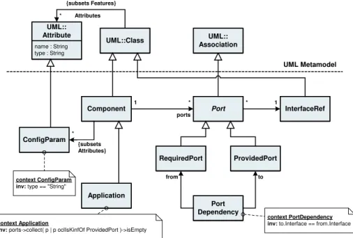
Again, we show the meta-model for this aspect of the model. Since we use a UML-based concrete syntax (as exemplified in the interface meta-model) we extend the UML meta-model.
The Component type extends UML:Class (this is why we model the components as UML classes with a ¡¡component¿¿ stereotype in the concrete example model in figure 7). A Component has a number of Ports. A Port is modeled as a subtype of UML::Association. A Port references an InterfaceRef (it cannot technically directly reference Interfaces because they are defined in another meta-model. The InterfaceRef plays the role of a Proxy [6] for the Interface). Ports are abstract; concrete subtypes are defined in the form of RequiredPort and ProvidedPort. Also note the concepts of Applications, which are components that do not offer any services themselves; this is expressed by the OCL constraint that requires the ports association to only contain RequiredPort objects.
Finally, a concrete system must be specified by defining component instances, con-tainers and (hardware) nodes, as well as connections on physical and logical level. We use an XML based concrete syntax for this aspect. The following shows a part of the deployment definition of the example weather station. With the background of the pre-vious explanations (and the meta-model for the deployment which follows directly after
Component 1 * Port RequiredPort ProvidedPort InterfaceRef * 1 Application ports context Application
inv: ports->collect( p | p oclIsKinfOf ProvidedPort )->isEmpty
Port Dependency
to from
context PortDependency inv: to.Interface == from.Interface
ConfigParam * UML::Class name : String type : String UML:: Attribute {subsets Features} * Attributes {subsets Attributes} context ConfigParam inv: type == "String"
UML Metamodel UML::
Association
Fig. 10. Meta-model for components and ports
this example) the meaning of this model should be understandable without further ex-planation.
This part of the system has a meta-model, too. It is shown in the next illustra-tion. The central concept is the System. A System consists of a number of Nodes, each Node itself consists of Containers. Containers contain a number of ComponentIn-stances which reference a Component as their type. On the other hand, Systems also contain a number of Connectors. They connect a provided and a required port of two ComponentInstances in order to allow these two instances to communicate through the respective ports. Finally, a Connector has a type, which implements one of several com-munication strategies, such as comcom-munication through CAN bus, through a local direct call, or through shared memory.
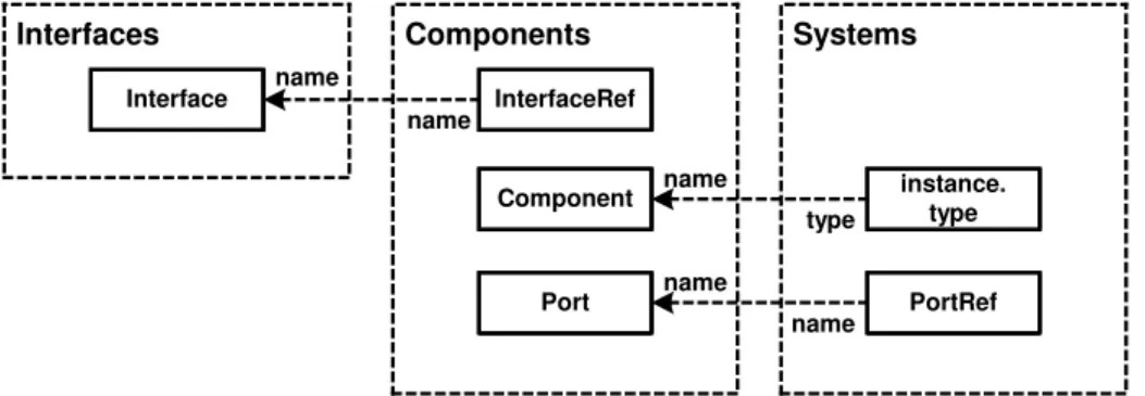
From these three different models, an overall model can be composed (this is done in code generator’s first phase, on AST level). This overall, merged model will subse-quently be used as the input to the code generation phase of the generator. The overall model thus consists of several partial models describing different aspects of the overall system. However, in order to generate a useful system, the code generator (described in more detail below) must consider all the aspects at the same time. This requires a way to join the models; technically, this is done by using different parser front-ends on the generator (see below). However, we also need to make sure that the models can be joined logically. For example, in the component model, we must reference an interface defined in a text file. As a consequence, we use proxies [6] in the meta-model (called ref-erences). The following illustration shows how the various models are joined logically.
<system name="weatherStation"> <node name="main"> <container name="main"> <instance name="controller" type="Control"/> </container> </node> <node name="inside"> <container name="sensorInside"> <instance name="tempInside" type="TemperatureSensor"> <param name="unit" value="centigrade"/> </instance>
</container> </node>
<node name="outside"></node>
<!-- temperature sensor outside --> <connector name="toSensorTempOutside"> <providedPort instance="tempOutside" port="measurementPort"> <requiredPort instance="controller" port="sensorsPort"> </connector> <connector name="fromSensorTempOutside"> <providedPort instance="controller" port="controllerPort"> <requiredPort instance="tempOutside" port="controllerPort> </connector>
<!-- humidity sensor outside -->
<connector name="toSensorHumOutside">...</connector> <connector name="fromSensorHumOutside">...</connector> <!-- temperature sensor inside -->
<connector name="toSensorTempInside">...</connector> <connector name="fromSensorTempInside">...</connector> </system>
* ComponentRef name : String Component Instance 1 System * Node * Connector Type 1 type DirectCall
Connector SharedMemoryConnector ConnectorCAN
{open}
Provided
PortRef RequiredPortRef
id : String
Connector
1 source 1 target
*
context Connector
inv: source.interface == target.interface
Container
*
Fig. 12. Deployment meta-model
It means that a component model uses InterfaceRefs to reference interfaces defined in the interface model; the system model uses the type attribute of ComponentInstances to refer to Components defined in the component model as well as PortRefs to reference the Ports defined as part of Components.
Tooling. In addition to a UML tool and a text editor (to create the various models shown
above) the tooling mainly consists of a model-driven code generator, the openArchitec-tureWare [oAW] toolset in our case. The generator has three primary responsibilities:
– Parse the various models and join them together; inconsistencies must be detected
and reported
– Verify the model against the meta-model of the domain. If the model does not
conform to the domain meta-model, report errors.
– In case the model is fine, generate the target code for the various platforms
In the tradition of programming language compilers, the generator works in several phases, as illustrated in Fig. 14.
In the first phase, one or several model parser front-ends read the model. This results in the representation of the model as an object graph inside the code generator. The classes used to represent the object graph directly represent the domain meta-model. This is where meta-model constraints are checked (they are implemented as part of the meta-classes). In the second phase, code generation templates are used to actually
name InterfaceRef type name Interface instance. type name Component Interfaces name name Components PortRef Systems Port
Fig. 13. Relationships among the meta-models
specification (model)
instance of
model parser metamodelinstance templateengine
metamodel
templates written in
terms of
output code
generate output code. For illustrative purposes, we show a skeleton implementation of the Interface meta-class.
public class ECInterface
extends generatorframework.meta.uml.Class { }
Fig. 15. Initial definition of the ECInterface meta-class
The defined class in Fig. 15 is an ordinary Java class. We inherit from the UML::Class meta-class, because
– It makes the ECInterface a model element, i.e. a valid generator meta-class, – It inherits the properties of UML::Classes, specifically the fact that it can have
operations, that it is in a package, etc.
– It allows use to use stereotypes on UML::Classes to represent instances of
inter-faces.
public class ECInterface
extends generatorframework.meta.uml.Class { public String CheckConstraints() {
Checks.assertEmpty( this, Attribute(), "must not have attributes." ); }
// more ... }
Fig. 16. ECInterface meta-class with constraints
This same approach can be applied in many other circumstances, for example, to ensure that the port names of components are unique:
Generating code. Code generation is based on templates. A template is basically a
piece of code with escapes in it that can access the model (represented as an object graph in the generator). The following piece of code is a simple example that generates a C header file for a component implementation. Templates consist of two kinds of text:
– The commands within the ”guillemots” are used to iterate over the model and thus
to control code generation.
– Text outside the ”guillemots”is code to be generated. It is literally copied into the
generated code file.
– Within the to-be-generated code the ”guillemots”-escape can be used to reference
public class Component extends generatorframework.meta.Class { public String CheckConstraints() {
Checks.assertEmpty( this, Operation(), "must not have attributes." );
Checks.assertEmpty( this, Generalization(),
"must not have superclasses or subclasses." ); Checks.assertEmpty( this, Realization(),
"must not implement any interface." ); Checks.assertUniqueNames( this, Port(),
"a component’s ports must have unique names." ); }
// more ... }
Fig. 17. Constraints Checks for the Component meta-class
<<DEFINE PortHeader(connector) FOR Port>> <<FILE "include/"Component.Name"_"Name".h">> /**** Port Header File ****
* * Type: <<TypeInfo>> * Name: <<Name>> * Component: <<Component.Name>> * Interface: <<Interface.Name>> */ <<LET Component.AllUpperCaseName>>_<<AllUpperCaseName AS portPrefixUpperCase>> #ifndef <<portPrefixUpperCase>>_H #define <<portPrefixUpperCase>>_H #include <<middleware_types.h>> <<EXPAND Body(connector)>> #endif <<ENDLET>> <<ENDFILE>> <<ENDDEFINE>>
<<DEFINE Body(connector) FOR ProvidedPort>> <<IF isCSPort>>
<<EXPAND Util::ExternDecl(Component.Name>>_<<Name) FOREACH Interface.Operation>>
<<ENDIF>> <<ENDDEFINE>>
Parsing input models. Parsing of the input models is done using generator front-ends,
as shown above. Since we need to parse several models for a certain generator run, we use the composite design pattern [6] to build a front-end that itself contains front-ends for the various models we need.
package util;
public class EmbeddedComponentsInstantiator extends CompositeInstantiator {
private String systemConfFile =
System.getProperty("EC.SYSTEM"); private String interfaceFile =
System.getProperty("EC.INTERFACE"); private String componentsFile =
System.getProperty("EC.COMPONENTS"); public EmbeddedComponentsInstantiator () {
// a front-end that reads the UML model add( new XMIInstantiator( componentsFile ) ); // a front-end that reads the XML system spec // use ecMetamodel as package prefix when // attempting to load meta-model classes
add( new XMLInstantiator( systemFile, "ecMetamodel" ) ); // a front-end that reads the textual spec
// for the interfaces
add( new JCCInstantiator( interfaceFile ) ); }
}
Fig. 19. Instantiator that reads the various models
How the various front-ends work internally is beyond the scope of the book. Basi-cally, they read the models and create an object graph from them.
Overall setup. Since we use several aspect models with different concrete syntaxes,
the actual setup is somewhat more complicated, as shown in the next illustration. The interfaces are represented with a textual DSL. Components are represented using pro-filed UML models; the deployment (or systems) are described using XML. All these different partial models refer to their respective parts of the meta-model. The complete meta-model is implemented as Java classes as illustrated above, independent of their
concrete syntax. So, while a model is represented in different files using different con-crete syntax, all the model parts are represented as Java objects once they have been parsed by the respective instantiator (parser, front-end). This is also the place where the references among the model parts are dereferenced (the proxy is supplied with a reference to its delegate object). At this stage, the generator back-end uses the code generation templates to generate the output.
Application Domain Architecture Generator
Metamodel DSL
(Interfaces)
Inter-faces onentsComp- Sys-tem
Model <<instanceof>> ASCII concrete syntax meta model DSL (components) metamodel UML Profile concrete syntax DSL (Systems) metamodel XML concrete syntax
Inter-faces Comp-onents Sys-tem
Generator Backend se m an tic s XML Instantiator Textual Instantiator XMI
Instantiator InstantiatedMetamodel
<<instanceof>> Transformations Meta-Metamodel (Java) << in sta nc eo f> > Manually Coded Application Logic Platform Generated Code
Fig. 20. Overall tool chain and artifacts
3.1 Resource Optimization
Due to the generative approach we were able to conduct experiments concerning op-timized code generation for efficient resource allocation. Since this is one of the key requirements for the embedded world we invested considerable efforts into this topic.
In our experiments we reached an additional memory allocation for middleware based embedded software of 1KB of ROM and 300 Bytes of RAM for an typical event based communication pattern in the automotive domain. The performance of the mid-dleware based software was not significantly slowed down either, which fortifies the practicability of our approach.
4
Conclusions
Advantages of this approach. A model-driven approach to software development yields
a number of advantages, some of them especially important in the context of embedded systems. The following list briefly explains some of these - the order is not significant.
– First of all, developer productivity is improved, since repetitive, aspects need not
be coded manually over and over again. Many target platforms (such as real-time operating systems) require a lot of ”bookkeeping” code and configurations that fall in this category.
– The models capture knowledge about the application structure and functionality
much more explicitly, free from “implementation clutter”.
– Different concerns are separated explicitly. Each of them (or subsets) are model
led using their own model, making them explicit and thus more tractable, easier to change and potentially reusable.
– Communication with the various stakeholders is simplified, since each stakeholder
need only take a look at the models of the aspect they are interested in.
– It is easier to react on changes, since the change often affects one piece of code
only. Code (and other artifacts) that needs to change as a consequence is simply regenerated.
– The transformations capture design knowledge for the target platform. They thus
serve as a form of “codified best practices”.
– Reuse (of the platform, DSLs, etc.) is made possible.
– Typically, the software architecture improves since the definition of a stringent
soft-ware and system architecture is necessary. Otherwise code cannot be generated ef-ficiently.
– Code quality is improved, since most of it is generated from templates. It is easier
to ensure templates generate high-quality code than to assure this for each piece of code manually.
– Portability is simplified. If a different platform should be used, only a new set of
templates needs to be created (which, of course, can be non-trivial, too).
– MDSD increases flexibility without inducing runtime overhead. The generated
code can be strongly typed, maybe even relying on static memory allocation only, while flexibility is still there. The flexibility is realized at generation time and compile-time, not during runtime.
– Since the mapping from models to implementation code is determined by templates
(i.e. is the same each time), the quality of service characteristics of the implemen-tation (timing behavior, memory consumption, performance) are known to some extent. This can be a big advantage in embedded system development.
– Since error messages are not just reported by the compiler when compiling the
im-plementation code, but also by the transformer/generator when reading the models, the error messages can be much more expressive. A model contains much more domain semantics that can be reported as an error messages compared to imple-mentation code.
Prejudices. Since we keep hearing the same prejudices against MDSD over and over
again, here are some simple statements that developers should consider.
– MDSD does not require UML, use any DSL that is suitable for your domain. – Generated code can be very readable, can include comments, etc. Generated code
is often even easier to understand than manually written code, since it is more structured (it is based on the “rules” in the transformations)
– MDSD does not require a waterfall process. MDSD works well using
incremen-tal, iterative processes. This is true for application development as well as for the development of the domain architecture.
– MDSD is quite agile, since - once a domain architecture is in place - it allows to
come up with running applications very quickly.
Challenges. There is no “free lunch”. So, even while model-driven software
develop-ment has a great number of benefits, there are also some drawbacks/challenges that need to be addressed. For reasons of space we cannot go into details, and we recom-mend reading [21].
– The development process has to take into account the two development paths:
do-main architecture development and application development. An approach that has worked in practice is to have two kinds of teams (domain architecture and appli-cation development). The appliappli-cation development teams play the role of the cus-tomers for the domain architecture development. An iterative process with regular “deliverables” will minimize the problems.
– There are no universal standards yet. Using MDSD will always tie the development
to a number of tools. With the OMG’s MDA standard, this should be less of a problem in the future. Today the impact of the problem can be minimized by relying on open source tools.
– The concepts and tools need to be understood. Specifically for “traditional”
embed-ded developers this can be quite a ’cultural shock’. Terms like meta-model, DSL, etc. are often not very well-known, and not readily accepted. The best approach to attack this problem is to run an example-driven education effort that first con-vinces people of the benefits of the approach, and then goes into some details of the concepts behind it.
Practical experience and related work. Model-Driven Software Development has a
long success history, although it did not always appear under that name. MDA [14], Generative Programming [3], Domain-Specific Modeling [2] and Domain-Driven De-velopment are all either different names for MDSD or special “flavors” of the general MDSD approach. Specifically, MDA is gaining more and more importance in the en-terprise software development area.
In the embedded world, generating code from models is also a well-known ap-proach, although use of such code in production systems is only slowly being adapted. Tools like ASCET [4], Matlab/Simulink [9] or Statemate [8] are well-known to embed-ded developers.
Using MDSD to implement (component/container-based) middleware is a rather novel approach, though. The authors, as well as other people known to the authors have
been using the approach with overwhelming success in the domains such as automotive, mobile phones or scientific computing. The productivity boosts promised by MDSD have largely been realized. Acceptance with developers was good after they had seen that they could understand the generated code, and that it also was efficient.
In the automotive domain, the AUTOSAR consortium [1] is currently in the process of standardizing an architecture and process conceptually similar to the one explained in this chapter.
References
1. The AUTOSAR Consortium. AUTOSAR homepage. http://www.autosar.org/ 2. Domain Specific Modelling Fourm. http://www.dsmforum.org/
3. U. Eisenecker, K. Czarnecki. Generative Programming. Addison-Wesley 2000
4. ETAS Group, ASCET Homepage. http://en.etasgroup.com/products/ascet sd/index.shtml 5. T. Ewald. Transactional COM+: Building Scalable Applications. Addison-Wesley, 2001 6. Gamma, Helm, Johnson, Vlissides. Design Patterns. Addison-Wesley 1995
7. K. Henney. Inside Requirements. Programmer’s Workshop column in Application Development Advisor, May/June 2003 (http://www.two-sdg.demon.co.uk/curbralan/papers/InsideRequirements.pdf)
8. I-Logix, Statemate homepage. http://www.ilogix.com/statemate/statemate.cfm 9. The Mathworks, Matlab Homepage. http://www.mathworks.com/
10. The openArchitectureWare generator framework. http://sourceforge.net/projects/architecturware/ 11. Object Management Group, Minimum CORBA. http://www.omg.org/technology, 2004 12. Object Management Group, Real-Time CORBA. http://www.omg.org/technology, 2004 13. Object Management Group, CORBA Component Model Specification (CCM).
http://www.omg.org/technology, 2004
14. OMG, Model-Driven Architecture (MDA). http://www.omg.org/mda 15. OSGi Alliance, http://www.osgi.org, 2004
16. D.L. Parnas. On the Criteria To Be Used in Decomposing Systems into Modules. Communi-cations of the ACM, Vol. 15, No. 12, December 1972
17. C. Schwanninger, E.Wuchner, and M. Kircher. Encapsulating Cross-Cutting Concerns in System Software, Workshop on Aspects, Components, and Patterns for Infrastructure Soft-ware, AOSD 2004 conference, Lancaster, UK, March 22-26, 2004
18. Sun Microsystems, Java2 Enterprise Edition (J2EE). http://java.sun.com/j2ee/, 2004 19. M. Voelter, M. Kircher, U. Zdun. Remoting Patterns: Foundations of Enterprise. Internet and
Realtime Distributed Object Middleware, John Wiley & Sons, 2004
20. M. Voelter. MDSD Tutorial, http://www.voelter.de/services/mdsd-tutorial.html
21. M. Voelter, T. Stahl, J. Bettin. Modellgetriebene Softwareentwicklung. dPunkt, to be pub-lished in 2004; an English version is in preparation.
22. M. Voelter, A. Schmid, E. Wolff. Server Component Patterns - Component Infrastructures Illustrated with EJB, John Wiley & Sons, 2002