Dr. K RAMA SUDHA, Professor
Department of Electrical Engineering, Andhra University, Visakhapatnam, Andhra Pradesh, India
K PADMAVATHI,
Research Scholar, JNTU,Kakinada, Andhra Pradesh [email protected]
Abstract
A Power Quality problem is an occurrence as a nonstandard voltage, current or frequency that results in a failure or mal operation of end user equipment. Power Quality (PQ) measures a wide range of power supply characteristics that can influence the performance of equipment and processes. The concept of custom power is to use power electronics in the voltage distribution system aiming to supply reliable and high quality power to sensitive users. Out of different custom power devices, the dynamic voltage restorer (DVR) is used to mitigate the voltage sag at the terminal of sensitive load. Several control methods are proposed for the DVR. This paper presents the modeling and analysis of DVR by comparing conventional DVR, DVR with PI controller and also DVR using Adaptive Neuro Fuzzy Inference System (ANFIS).
Keywords: Dynamic Voltage Restorer (DVR); Proportional Integral(PI) controller; Adaptive Neuro Fuzzy Inference System (ANFIS); Voltage Sag
1. Introduction
The quality of output power delivered from the utilities has become a major concern. The most concerning disturbance affecting power quality is voltage sag. Voltage sag is a sudden drop in the Root Mean Square (RMS) voltage and is usually characterized by the retained voltage [1]. The major source of voltage sag is short-circuits on the utility lines. Faults from the disturbed process will generate a momentary voltage sag in the electrical environment to the end user [2]. The Dynamic Voltage Restorer (DVR) is an effective Custom Power device which is used to mitigate the impacts of voltage sags on sensitive loads in distribution systems [4]. DVR is used for balancing the load voltage due to harmonics and unbalancing at the source end, in order to eliminate switching transients. DVR has to inject voltages with large magnitude, which is completely undesirable. By varying load voltage angle, if the required nominal voltage is injected at the system frequency, the control operation will be efficient. To realize this, a method for estimating the frequency from the sampled injected voltage signal has been presented.
effects can be very expensive for the customer, to avoid equipment damage [8]. There are many different methods to mitigate voltage sags and swells, but the use of a DVR is considered to be the most cost efficient method. DVR with PI controller has a simple structure and offers a satisfactory performance over a wide range of operating conditions. The main problem of Conventional Controllers is the correct tuning of the controller gains. When there are variations in the system parameters and operating conditions, the controller may not provide the required control performance with fixed gains. To cover wide range of operating conditions Fuzzy Logic approach may be employed, but the problem arises with the parameters associated with the membership functions and the rules which depend broadly on the intuition of the experts. If it is required to change the parameters, it is to be done by trial and error only. To overcome the above problem and improve the adaptability of the controller, Adaptive Neuro-Fuzzy Inference System (ANFIS) is used [5]. In ANFIS, Fuzzy Inference System is generated based on the chosen set of input/output data.
In this paper, DVR with ANFIS controller is proposed and tested on the system considered for study with the application of three-phase to ground fault for 100ms. The efficacy of the proposed controller is compared with Conventional Proportional and Integral Controller and also with individual performance of Dynamic Voltage Restorer.
2. Dynamic Voltage Restorer
Power Quality problem is the main concern in electricity industry. Power Quality includes a wide range of disturbances such as voltage sags/swells, flicker, harmonics distortion, impulse transient, and interruptions. And the majority of power quality problems are due to different fault conditions. These conditions cause voltage sag. Voltage sag can occur at any instant of time, with amplitude ranging from 10-90% and a duration lasting for half a cycle to one minute. It is generally caused by faults in the power system and characterized by its magnitude and duration. The duration of voltage sag depends on clearance of fault by using protective devices. Power Electronics based devices installed at medium voltage level for mitigation of power quality phenomenon, known as “Custom Power Devices”, able to deliver customized solution to power quality problems. Voltage sag and interruption mitigating devices are normally connected between the supply and the load.
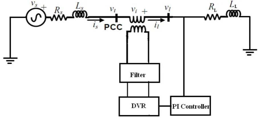
Dynamic voltage restorer is a series connected device designed to maintain a constant RMS voltage across a sensitive load. The structure of DVR is shown in Fig.I. The DVR consists of:
2.1 Voltage Source Inverter (VSI):
Voltage Source Inverters converts the dc voltage from the energy storage unit to a controllable three phase ac voltage. The inverter switches are normally fired using a sinusoidal Pulse Width Modulation scheme.
Injection Transformers: 2.2 Injection Transformer:
Injection transformers used in the DVR plays a crucial role in ensuring the maximum reliability and effectiveness of the restoration scheme. It i s connected in series with the distribution feeder.
2.3 Passive Filters:
Passive Filters are placed at the high voltage side of the DVR to filter the harmonics. These filters are placed at the high voltage side as placing the filters at the inverter side introduces phase angle shift which can disrupt the control algorithm.
2.4 Energy storage device:
Fig.1 Structure of Dynamic Voltage Restorer
3. COMPENSATION OF VOLTAGE SAG USING DVR
The single line diagram of test system is shown in Fig.2. The voltage source is connected to a feeder with an impedance of
R
s
jX
s. The load is balanced and the impedance of the load is given byR
L
jX
L. Fig 3.Shows the test system with 3phase fault. s
v
is the source voltage in volts tv
is voltage at point of common coupling in voltss s
R
jX
is impedance of the feeder in ohmsl
v
is the load voltage in voltage L LR
jX
is the load impedance in ohmss
i
is the source current andi
l is the load current in ampsFig.2 Single line diagram of test system
DVR is connected between a terminal bus and load bus. The control technique to be adopted depends on the type of load as some loads are sensitive to only magnitude change whereas some other loads are sensitive to both magnitude and phase angle shift. Control techniques that utilize real and reactive power compensation are generally classified as pre-sag compensation, in-phase compensation and energy optimization technique. The single line diagram of DVR connected in the distribution system
Fig.4 single line diagram of dynamic voltage restorer connected to distribution system
When the source voltage drops or increases, the dynamic voltage restorer injects a series voltage through the injection transformer so that the desired load voltage magnitude can be maintained. The series injected voltage of the DVR,
v
kcan be written as:k t l
v
v
v
--- (1)
v
k is the series injected voltage in the distribution system such that it mitigates the voltage sag and regulates the load bus voltage,v
l to a reference valuev
l*. It is pre specified value.The reference voltage ofthe DVR can be written as:
k t l
v
v
v
(2)
4. Compensation Of Voltage Sag Using DVR With PI Controller
A proportional-integral (PI) controller drives the plant to be controlled with a weighted sum of the error (difference between the actual sensed output and desired set-point) and the integral of that value. An advantage of a proportional plus integral controller is that its integral term causes the steady-state error to be zero for a step input. PI controller input is an actuating signal which is the difference between
v
l* andv
l . Fig.5 shows theFig.5 Schematic of a PI Controller
The output of error detector is
l
v
* -v
l (3)l
v
* equal to 1 p.u. voltagel
v
voltage in p.u. at the load terminalsThe controller output when compared at Pulse Width Modulation (PWM) signal generator results in the desired firing sequence. The modulated angle is applied to the PWM generators.
The sinusoidal signal
v
control is phase-modulated by means of the angle δ and the modulated three-phasevoltages are given by
sin(
)
a
v
wt
(4)sin(
)
b
v
wt
(5)sin(
)
c
v
wt
(6)The equivalent circuit model of DVR with PI controller is shown in Fig.6. The system parameters are listed in Table I.
Voltage sag is created at load terminals via a three phase fault. The load voltage is sensed and passed through a sequence analyzer. The magnitude of change in load voltage is compared with reference voltage,
v
l*5. DESIGN OF DVR WITH ANFIS CONTROLLER
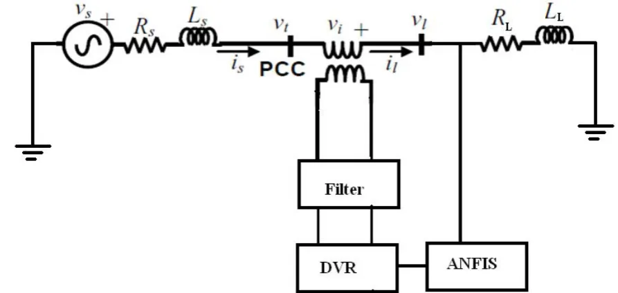
Adaptive –Neuro based Fuzzy Inference System (ANFIS) is a Fuzzy Inference System (FIS) which may be implemented in the framework of adaptive networks. ANFIS serves as a basis for constructing a set of fuzzy rule base with appropriate membership functions to generate the stipulated input and output pairs. The generated FIS maps input characteristics to input membership functions, and then input membership functions to the rule base. The generated rules are mapped to a set of output characteristics and the output characteristics to the output membership function to a single valued output.
5.1 Creating Fuzzy Inference System
The proposed ANFIS controller is trained using the generated FIS by mapping the calculated input output data. Hybrid learning algorithm is used to train the proposed ANFIS controller during 20 epochs. Fig.7 shows the structure of generated FIS with two inputs and single output each of having three trapezoidal membership functions. Fig.8 shows the equivalent circuit of DVR with ANFIS.
Fig.8 Equivalent Circuit Of Dynamic Voltage Restorer With ANFIS
6 SIMULATION RESULTS AND DISCUSSIONS
The performance of the proposed controllers on the test system shown in Fig.1 with respect to voltage sag compensation is tested during a three phase to ground fault of 100ms. The parameters of the test system are given in Table 1. It is assumed that the magnitude of the load voltage is maintained at 1 per unit (pu) and the DVR is modeled to inject the voltage to the test system during occurrence of voltage sag.
6.1 System Parameters
Table 1 system parameters
Sl.No System Quantities Values
1 Source Voltage 11KV
2 System Frequency 50Hz
3 Line Impedance Rs=0.605Ω
Ls=15.4mH
4 DC Bus Voltage 1.5KV
5 Filter Inductance Lf=61.62µH
6 Filter Capacitance Cf=2348.8µF
7 Load resistance 72.6Ω
8 Load inductance 173.288mH
9 Series transformer 10MVA,1.5KV/11KV
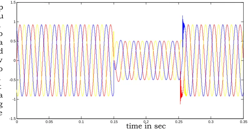
Fig. 9 per unit magnitude of load voltage during three phase fault without DVR
Fig.10 per unit magnitude of RMS load voltage during three phase fault
The effect of the DVR is tested on the test system by incorporated the DVR in the line such that it injects the voltage during the occurrence of the sag in the magnitude of the voltage. Fig.11 and Fig.12 shows the magnitude of three-phase per unit load and the magnitude of per unit RMS load voltage with DVR respectively. From the figures it is well understood that the mitigation of the voltage sag improved from 50% to 80% and the effect of the transients after the fault in the test system is reduced completely.
0 0.05 0.1 0.15 0.2 0.25 0.3 0.35
0 0.1 0.2 0.3 0.4 0.5 0.6 0.7 0.8 0.9
time in sec
P
u
r
m
s
v
o
l
t
s
sdsd0 0.05 0.1 0.15 0.2 0.25 0.3 0.35
-1.5 -1 -0.5 0 0.5 1 1.5
Fig.11 per unit magnitude of load voltage during three phase fault with DVR
Fig.12 per unit magnitude of RMS load voltage during three phase fault with DVR
For the system considered for study with DVR, in order to compensate the sag occurred during the three phase fault an ANFIS controller is designed. To generate the fuzzy inference system and for training of the ANFIS controller, initially the conventional Proportional Integral (PI) controller which can effectively mitigate the occurrence of sag in voltage than the DVR system is designed. The PI parameters are selected as KP=0.5 and KI=50.The effect of the ANFIS with DVR and conventional PI is tested on the test system by incorporating each controller individually. Fig.13 and Fig.14 shows the magnitude of three-phase per unit load voltage with DVR& PI controller and with DVR & ANFIS respectively. Fig.15 shows the Comparision of pu RMS load voltage of a test system with DVR & ANFIS and with DVR & PI. From the figures it is evident that the DVR with ANFIS
0 0.05 0.1 0.15 0.2 0.25 0.3 0.35
0 0.1 0.2 0.3 0.4 0.5 0.6 0.7 0.8 0.9 1
time in sec
P
u
r
m
s
v
o
l
t
s
0 0.05 0.1 0.15 0.2 0.25 0.3 0.35
-1.5 -1 -0.5 0
time in sec
controller showed better performance than the PI controller during three-phase to ground fault for duration of 100ms. When the above figures of pu RMS load voltages are observed, it is clearly understood that the % mitigation of sag has improved in the system incorporated with DVR and ANFIS. Fig.15 clearly shows that the effect of transients is completely reduced and the settling time is improved to 0.25s.
Fig.13 per unit magnitude of load voltage during three phase fault with DVR and PI Controller
Fig.14 per unit magnitude of load voltage during three phase fault with DVR and ANFIS Controller
0 0.05 0.1 0.15 0.2 0.25 0.3 0.35
-1.5 -1 -0.5 0
p
u
l
o
a
d
v
o
l
t
a
g
e
1 1.5
time in sec
0 0.05 0.1 0.15 0.2 0.25 0.3 0.35
-1.5 -1 -0.5 0 0.5 1 1.5
time in sec
p
Fig.15 per unit RMS load voltage using DVR with ANFIS & DVR with PI
Table.2 shows the comparative analysis in mitigation of sag in load voltage with respect to time in seconds by incorporating various controllers individually. From the table it is shown that the performance of the test system has improved with DVR and ANFIS in mitigating sag in the pu magnitude of load voltage and pu magnitude of RMS load voltage.
Table.2 Time to mitigation of sag
Comparative Analysis in Mitigation of Sag in Load Voltage
Sl No
Type of Controller
Time to mitigation of sag
1 DVR 1.4ms
2 DVR with PI 0.9ms
3 DVR with ANFIS 0.7ms
7. CONCLUSION
Dynamic Voltage Restorer is an effective device to compensate the voltage sag in distribution system. In this paper the control strategies of the compensation of voltage sag by using DVR are presented. The proposed controller is generated by ANFIS training according to a given input and output data. The performance of the proposed DVR with ANFIS controller is efficient than conventional PI controller to compensate the voltage sag on test system considered for study with the application of three-phase to ground fault for 100ms.
8. REFERENCES
[1] Bollen M. H. J,(2000) :Understanding Power Quality Problems; Voltage Sags and interruptions, ser. IEEE Press Series on Power Engineering, Piscataway, NJ.
[2] Choi, S.S.; Li, B.H.; Vilathgamuwa, D.M.(2000) : A Comparative Study Of Inverter- And Line-Side Filtering Scheme In Dynamics Voltage Restorer, Power Engineering Society Winter Meeting,. IEEE. Vol. 4, pp. 2967-2972.
0 0.05 0.1 0.15 0.2 0.25 0.3 0.35
0 0.5
time
PU
R
M
S L
O
A
D
VO
[3] Ghosh A ; Ledwich G.( 2001) : Structures and control of a dynamic voltage regulator (DVR), in Proc. IEEE Power Eng. Soc. Winter Meeting, Columbus, OH.
[4] Ghosh A ; Ledwich G.( 2002) : Power Quality Enhancement Using Custom Power Devices, Norwell, MA: Kluwer.
[5] Jyh-Shing Roger Jang ,(May/June 1993) : Adaptive-Network-Based Fuzzy Inference System, IEEE Transaction on Systems, Man, and Cybernetics, VOL.23, No.3.
[6] Ghosh A;Jindal A K; Joshi A, (Oct. 2003). “Inverter control using output feedback for power compensating devices,” IEEE TENCON 2003 Conf. on Convergent Technologies for Asia-Pacific Region, Vol. 1, pp. 48- 52, 14-17 .
[7] Chris Fitzer; Mike Barnes; Peter Green(2004): Voltage Sag Detection Technique for a Dynamic Voltage Restorer , IEEE Transactions on Power Delivery, Vol. 40, No. 1, pp. 203-212, January/February. 2004.
[8] Paisan Boonchiam ;Nadarajah Mithulananthan,(2006): Understanding of Dynamic Voltage Restorers Through MATLAB Simulation, ThammasatI nt. J. Sc.T ech.,V ol. i 1, No. 3, July-September..
[9] Amit Kumar Jindal; Arindam Ghosh ; Avinash Joshi,(2007): Critical load bus voltage control using DVR under system frequency variation, Electric Power System Research,EPSR-2508.