Copyright © 2015 IJTEEE.
Comparative Analysis Of Different Dispersion
Compensation Techniques On 40 Gbps Dwdm
System
Meenakshi, Jyotsana, Jyoteesh Malhotra
Department of Electronics and Communication Engineering GNDU RC, Jalandhar, Punjab
Email: [email protected]
ABSTRACT: Dense wavelength division multiplexing (DWDM) is a fibre optic technology that can transmit multiple information streams simultaneously over a single fibre. This paper focusing on to implementation of comparative analysis of dispersion compensated configuration for 40 Gbps dense wavelength division multiplexing (DWDM) system with modulation format (NRZ) and compensation schemes (Pre, Post and symmetrical compensation) at same bit rate 40 Gbps with standard and dispersion compensated fibre on the basis of Q-factor, eye –diagram and bit error rate for fixed gain EDFA and length both type of fibre. On the basic comparison of that Symmetrical compensation is superior to pre and post compensation schemes and gives better results even at high bit rate 40Gbps its transmission distance is 480 km with BER 10-28 and Q factor 10.92 with NRZ format.
Keywords: DWDM; DCF; PRE; POST; SYMMETRICAL.
1. INTRODUCTION
In order to achieve dense wavelength division multiplexing (DWDM) systems with high spectral efficiency, it is attractive to operate at bit rate 40 Gb/s per channel(1-4). For DWDM systems in which the data rate is >10 Gb/s channel, the deleterious effects of dispersion and nonlinearity must be managed to achieve transmission over any appreciable distance. Dispersion management, utilizing alternating fibre segments of opposite dispersion values, is a key technique that keeps the total accumulated dispersion low while suppressing most nonlinear effects. In dispersion-managed systems utilize single-mode fibre (SMF) and dispersion-compensated fibre (DCF), the positive dispersion of SMF can be by the large negative dispersion of DCF. In high-capacity wavelength-division-multiplexed (WDM) transmission systems, the increase of the channel bit rate from 10 to 40 Gbps and above changes the nature of the dominant nonlinear impairments [7]. As transmission distance and number of channels increases, signals become more vulnerable to a number of debilitating fibre nonlinear effect. The transmission of optical signals in an optical communication system may be limited by optical effects such as chromatic dispersion. Several methods have been proposed to overcome the impairments caused by chromatic dispersion including fibre Bragg grating [8], optical phase conjugation [9, 10], dispersion compensating devices. The use of power and dispersion compensated fibre (DCF) is an important method to upgrade the already installed links of single mode fibre [11]. The high value of negative dispersion is used to compensate for positive dispersion over large lengths of ordinary fibre. Investigated the pre-, post- and symmetrical dispersion compensation methods for 10 Gbps non-return to zero (NRZ) links using standard and dispersion compensated fibres. The EDFA is used as a power compensator. The reported results of three compensation methods are compared and it is found that the symmetrical compensation method is superior to pre- and post-compensation methods
2. System Description
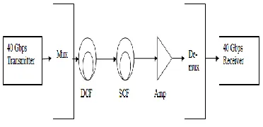
To investigate the performance of the three different power and dispersion compensation techniques, the structure is shown in Fig 1. Three fibre links are provided with the pre-, post- and hybrid-compensations are modelled as shown in Fig 2. In the pre-compensation, the optical communication system is pre-amplified and dispersion compensated by the PDCF of negative dispersion against the pumped SMF (PSMF), as shown in Fig. In the post-compensation, the optical communication system is post amplified and dispersion compensated by the PDCF of negative dispersion against the PSMF, as shown in Fig 3.
Fig 1 Block diagram of DWDM system
Copyright © 2015 IJTEEE. simulation and designing. It is an innovative, powerful and
rapidly evolving software design tool. It enables Users to test plan and simulate almost all type of optical link. The frequency range from 193.1 to 193.25 THz, data modulator and the optical multiplexer. Data modulators are connected to each output port of CW laser array then signals from data modulator is fed to 16 input ports optical multiplexer having bandwidth 40GHz. EDFA (Erbium doped fibre amplifier) is placed after every fibre to compensate the losses of the fibre with constant noise figure. In Receiver side of the system consists of demultiplexer, PIN detector and low pass Bessel filter. Signals are demultiplexed by the optical demultiplexer has 4 output ports and detected by the PIN detector. Pin diode has a responsivity [A/W] is 1 and dark current is 0.1 Na.
Fig 2 Schematic of Pre-Dispersion configuration
Fig 3 Schematic of Post-Dispersion configuration
Fig 4 Schematic Symmetrical Dispersion Configuration
Table 1 Simulation Parameter
Parameters Specifications
CW Laser Wavelength 1552.52nm
Data Rate 40 Gbps
Power 5 dB
Capacity 4x10 Gbps
Table 2 Fibre Parameters
Parameters SMF DCF
Length(Km) 50 10
Attenuation(dB/km) 0.2 0.5
Effective Area(µm2) 80 80
Dispersion(ps/nm-km) 16.75 -80
Dispersion
slope(ps/km/nm2) 0.075 0.075
Differential group
delay(ps/km) 0.2 0.2
3. Results & Discussions
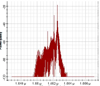
With the help of simulation setup, eye diagram of channels are analyzed and BER and Q –factor is measured. At 300 km using Post compensation Figure 2(a) and 2(c) shows eye diagram of channel 1 and channel 4 at 0.4nm channel spacing figure 2(b) and 2 (d) shows the spectrum of pre compensation technique. The BER achieved is 10-35, 10-37, 10-31, 10-42of channel 1, 2, 3 and 4.The Q-factor measured is 12.30, 12.65, 11.57 and 13.59.
Fig 2(a) Eye diagram for Channel 1
Copyright © 2015 IJTEEE. Fig 2(c) Eye diagram for Channel 4
Fig 2(d) Spectrum Analyzer for Channel 4
At 300 km using Post compensation
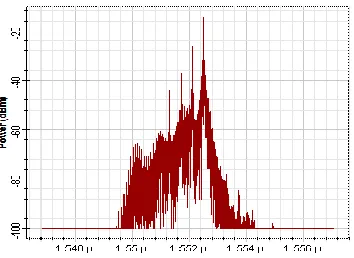
With the help of simulation setup, eye diagram of channels are analyzed and BER and Q –factor is measured. Figure 2(a) and 2(c) shows eye diagram of channel 1 and channel 4 at .4nm channel spacing figure 2(b) and 2(d) shows the spectrum of pre compensation technique. The BER achieved is 10-37, 10-40, 10-34 and 10-46 of channel 1, 2, 3 and 4.The Q-factor measured is 12.69, 13.18, 12.08 and 14.16 respectively.
Fig 3(a) Eye diagram for Channel 1
Fig 3(b) Spectrum Analyzer for Channel 1
Fig 3(c) Eye diagram for Channel 4
Fig 3(d) Spectrum Analyzer for Channel 4
At 480 km Using Symmetrical Compensation
Copyright © 2015 IJTEEE. Fig 4(a) Eye diagram for Channel 1
Fig 4(b) Spectrum Analyzer for Channel 1
Fig 4(c) Eye diagram for Channel 4
Fig 4(d) Spectrum Analyzer for Channel 4
Table 3 Comparison of Different Dispersion Compensated Configuration
S.No. Parameter Pre- Post- Symmetrical-
1 Transmission
Distance 300 300
480
2 BER 1031 10-34 10-28
3 Q-factor 11.57 12.08 10.92
4. CONCLUSION
It is concluded that the symmetrical configuration configuration is best as it covers transmission distance of 480 km with BER 10-28 and Q-factor of 10.92.
REFERENCES
[1] Choudhary, L.S.Garia, R.S.Shahi,”Comparative
analysis of DWDM system using different modulation and dispersion compensation techniques at different bit rates “International Journal of Advanced Research in
Computer and Communication Engineering Vol. 3, Issue 5, May 2014.
[2] S. Singh, R.S. Kaler,” Comparison of pre-, post- and symmetrical compensation for 96 channel DWDM system using PDCF and PSMF” Optik 124 (2013)
1808– 1813”
[3] Y. Malhotra, R.S. Kaler, “Compensating spectral loss
variations in EDFA amplifiers for different modulation formats”, Optik 122 (2011) 435–439.
[4] S. Singh, R.S. Kaler, “Transmission performance of 20×10 Gb/s WDM signals using cascaded optimized SOAs with OOK and DPSK modulation formats”, J.Opt. Commun. 266 (2006) 100–110.
[5] S.P.N. Cain, L. de Cal azans Calmon, M.J. Pontes, M.R.N. Ribeiro, M.E.V. Segatto,A.V.T. Cartaxo,”An analytical approximated solution for the gain of broadband Raman amplifiers with multiple Counter-pumps” IEEE J. Lightw. Technol. 27 (7),(2009) 944–
951.
[6] C.-H. Yeh, K.-H.Lai, Y.-J.Huang, C.-C. Lee, S. Chi, “Hybrid L-band optical fiber amplifier module with erbium-doped fiber amplifiers and semiconductor optical amplifier” Jpn. J. Appl. Phys. 43 (8A) (2004) 5357–5358.
[7] G.P. Agrawal, Applications of Nonlinear Fiber Optics, Academic Press, New York, 2001.
Copyright © 2015 IJTEEE. [9] T. Hoshida, O. Vassilieva, K. Yamada, S.
Choudhary,R.Pecqueur,H. Kuwahara,”Optimal 40 Gb/s modulation formats for spectrally efficient long-haul DWDM systems” IEEE J. Light wave Technol. 20 (12) (2002) 1989.