Hyderabad Metro Rail Viaducts Precast
Segmented Balanced Cantilever Method of
Launching of Segments by using LG & OH
Gantry at ROB’s
K. Shanmuga Sundaram Resident Engineer
Parsons Ltd. Riyadh Metro Rail Projects, Saudi Arabia
Abstract
This article presents the pre-cast segmented Balanced Cantilever Method of launching of segments by using LG and OH Gantry at ROB’s for Hyderabad metro rail rapid transit system in red, green and blue lines viaducts on particular locations where constraints obliged to have longer span lengths. Balanced cantilever erection precast segments have been used, combining the advantage of precast segment bridge (speed of construction) with balanced cantilever method advantages (longer spans).Total project length is an elevated viaduct spanning around 72 km of metro line and with 66 stations. Chosen bridge construction technique had to meet several requirements due to numerous constraints, among which speed of construction, geometry adjustability, environment disturbance. These project constraints led to use precast segmented by span ‘Balance Cantilever erection’ method. This construction method is the optimal one in terms of construction speed, quantity optimization, and construction quality and risk management.
Keywords: Metro Rail Bridge, Balance Cantilever Erection Method, Box Shape Precast Segment, Self- Launching Erection Gantry, Post-Tensioning
________________________________________________________________________________________________________ I. INTRODUCTION
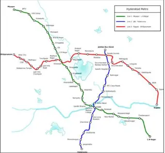
Hyderabad Metro Rail Limited (HMRL) was tasked with the responsibility of developing the Hyderabad Metro Rail (MRTS) Project consisting of 3 elevated lines with interchanges and having a total length of 71.16 kilometers crossing the heart of Hyderabad City.
The Government of Telangana (GOTS) awarded the development of the MRTS Project on a Design, Build, Finance, Operate, and Transfer (DBFOT) mode in Public-Private Partnership (PPP) to Concessionaire, M/s Larsen & Toubro Hyderabad Metro Rail Private Limited on 4 September 2010.
To monitor the project implementation and ensure quality standards of the project, HMRL engaged the services of an Independent Engineer viz M/s Louis Berger Consulting Pvt. Ltd., Gurgaon, Haryana on 8 February 2011 up to the end of the Project on 04-07-17.
The Metro Rail system under construction is a completely elevated system, generally run in the central median of the road. The viaduct structure for the elevated system is a box girder carrying two tracks on a single pier located on the median of the road.
Project Features
Table – 1 Project Features
Type of Construction Segmental Viaduct with some cast in situ spans in few cases including 8 Rail over bridges over the Railway Tracks of the Mainline Railway.
Stations
Total = 66 Elevated station(with 3 Interchange stations & 4 special stations) Corrior -1 - Miyapur to L B Nagar - 29.87 kilometres & 27 Stations (All elevated)
Corridor -2 - JBS to Falaknuma - 14.78 kilometres &16 Stations (All elevated) Corridor -3 - Nagole to Shilparamam - 26.51 km & 23 Stations (All elevated) Special Stations – 6 nos with three levels (Begumpet , Punjagutta , Jubilee Hills, Hi-Tech City,
Ameerpet and MG Bus Stand ,)
Railway Crossings 8 No’s out of which 2 are Steel bridges with longest span of 84m.
Rolling stock
Total Train set – 57, with 3 Cars per train set ( extendable to 6 cars train set) Car Body - Light Weight Stainless Steel/Aluminium
Air conditioner - 2 Roof mounted VAC for Saloon and One for Driver Cab Battery Back-up - Battery Backup upto one hour for emergency loads. Capacity/Train – Approx. 1000 passenger (8 Passenger/Square metre in standing area)
Track work
1435 mm (Standard Gauge), Ballastless (Main Line), UIC -60, HH Rails. Max. Axle load – 17 tonne.
Curved switches – 1 in 9 switches of radius 300m & 190m (main line), 1 in 7 switches of radius 190m (Depot)
Power Supply, Traction and SCADA System
25 kV, 50Hz AC (Over Head Catenary) and 33KV supply to each station from the Receiving Sub Stations (RSS) for Rail Systems.
(RSS) are located at Uppal, Miyapur, Yosufguda & MGBS for feeding the rail network all the time including during shut down of one RSS.
Signalling System Communication Based Train Control (CBTC) System- for headway of 90secs - first time in Indian Metros from Operation Control Center ( OCC)
Communication Radio System, DTS, Telephone, CCTV, Pass Announcement System, Pass Info Display Systems, Access Control, Voice Recording Systems.
E & M facilities Fire protection Systems, Electrical supply, UPS, Public Health Systems, Lifts & Escalators, Building Management Systems from OCC.
Fare Collection Automatic Fare Collection with centralised accounting and control. Contactless Smart Card (CSC) and Contactless Smart Token (CST) Depot Three (3) no’s Maintenance Depot @ Miyapur, Uppal (Main) and Falakanuma
Operating Speed Design Speed – 90Kmph on all 3 corridors Operating speed – 80Kmph on all corridors The system is designed to cater 50000 PHPDT for Corridors I & III and 35000 PHPDT for Corridor II.
The construction of the entire 71.16 km has been split into 6 stages with the first stage scheduled to be completed by March 2015 with the entire project scheduled to be completed by July, 2017.
In November 2013, L&T Hyderabad Metro started laying of rails on the metro viaduct between Nagole and Mettuguda, a stretch of 8 km. Hyderabad Metro Rail will provide disabled-friendly system.
The first train of the Hyderabad Metro Rail (HMR) came from Korea during the third week of May 2014. Stringent trial runs will commenced from June 2014 till February 2015, before the service on the first stage of the Nagole-Mettuguda sector is thrown open to the public on 21 March 2015.
The trail runs have started on the Miyapur to Kukatapally stretch in June 2015.
Three interchanges are planned at Mahatma Gandhi Bus Terminus, Parade Grounds and Ameerpet.
II. ELEVATED STRUCTURE OVERVIEW
L&T Infra has been responsible for elevated viaduct erection using segmental bridge technology, including pre-casting of all segments and their erection based on 3 construction methods:
Erection by means of launching gantry Erection on false work
Cantilever erection
Elevated Viaducts Deck Types
Elevated viaducts deck has been design as box girder beams. Their span length varied from 20m to 48m, with an average of 30m. For few longer spans different design has been chosen:
Box girders with three continuous spans has been installed, with an average span length of 45m. Cantilever method has been used for span length up to 45-85m.
More than 90% of elevated viaducts have been installed using span by span erection method. All segments installed using these methods are box girder shaped.
Fig. 2: Shape of Segments used for Shorter & Longer Span
Deck Classification
Spans erected using span-by-span method has been classified upon 3 parameters: Length varying from 20 to 44m
Designation (single track or double track) Alignment type (straight, curve, clothoid) Radius in plane
R < 300m=> none
300 < R< 2000m=> curved alignment, all segments are curved
Fig. 3: Curved Segments Alignment
Fig. 4: straight Segment Alignment for Radius >2000m
Pre-casting Yard
Due to the required number of segment, a pre-casting yard dedicated only to this Project has been able to be installed not far from erection site, out of city down town, in QUTUBULLAPUR & UPPAL casting yard. The casting yard laid over a around total area of 100 acres.
Fig. 5: General View of Segment Casting Yard
Match casting technique has been used on this Project to ensure a severe geometry control.
First, segment reinforcement is preassembled on rebar jig. After a first control, reinforcement cage, including post tensioning ducts, is installed in the casting form by means of tower crane. After mould closing and its geometry setting up, a second geometry control is preceded taking into previous casted segment geometry. Prior to concreting, post-tensioning ducts are filled with a rigid pipe in order to prevent any damage during concreting. After curing, casted segment is shifted nearby the form in order match the next segment to be concreted. Here below Fig. 6 presents the typical casting sequence for segment prefabrication using match casting.
Fig. 7:
After casting of the N+1 segment, N segment is transported to the storage area by means of gantry cranes, waiting for transportation the erection site dedicated trailer.
Box girders segments have been prefabricated on the pre-casting yard for both span by span erection & cantilever erection spans. The depth and thickness of the web & flange are governed by span by depth rations.
Advantage of Segmental bridge Construction
Very economical for long spans
Prefabricated segments provide more quality control
The structure can be fully loaded immediately after being pre-stressed The pre-stressed cables can be inspected and replaced at all times Low weight due to thin bridge sections
Industrialization of the construction process Innovations in construction equipment Low maintenance costs
Speed of construction, time taken less
Disadvantage of Segmental bridge Construction
High construction loading or high technology is used Need high safety precautions during construction Extra cost (due to more pre-stressing required)
III. PRECAST SEGMENTED BALANCED CANTILEVER METHOD OF LAUNCHING OF SEGMENTS BY USING LG AND OH GANTRY AT ROB’S
Balanced Cantilever Method
The principle of the method is to erect or cast the pier segment first, then to place typical segments one by one from each side of the pier, or in pairs simultaneously from both sides.
Each newly placed precast segment is fixed to the previous one with temporary PT bars, until the cantilever tendons are installed and stressed.
The closure joint between cantilever tips is poured in place and continuity tendons installed and stressed. In order to carry out this erection scheme, segments must be lifted and installed at the proper location.
The gantries can be categorized by their cross section: single truss, with portal-type legs, and two launching trusses with a gantry across. The twin box girders of the bridge in Bharath nagar ROB at Hyderabad Metro Rail Project was built with two parallel, but independent trusses (see Fig 7), with a typical obligatory span of 65.0m, segment weights of 60 tons.
Fig. 8: The Twin Box Girders of the bridge in Bharath Nagar ROB at Hyderabad Metro Rail Project
Normally, the balanced cantilever method is used for spans from 60 to 110 m, with a launching girder. One full, typical cycle of erection is placing segments, installing and stressing post-tensioning tendons, and launching the truss to its next position. It takes about 7 to 10 days, but may vary greatly according to the specifics of a project and the sophistication of the launching girder. With proper equipment and planning, erection of 16 segments per day has been achieved.
Case Study
Description Bharat
Nagar Chilkalguda Allugaddabavi Malakpet
Lakdi-ka-pul Begumpet Oliphanta Boiguda Corridor
(Stage) I (Stage 2) III (Stage 3) III (Stage 3)
I (Stage 5)
I (Stage 5)
III (Stage
3) III (Stage 3)
II (Stage 6)
Superstructure Steel Truss
Proposed Span Configuration
39m+ 65m +39m
39m+ 65m
+39m 40m+46m+27m
30m + 50m + 40m 36m+52m +31.5 m 39.5m+65m
+32.5m 83m 67m
Horizontal
alignment Straight
300m
(Transition) Straight
128m
(Curve) Straight
600m (Curve) 128m (Transition) 128m (Curve) Proposed Construction Methodology Launching Girder with Gantry Launching Girder with Gantry Launching Girder with Gantry Bridge Builder Bridge Builder Bridge Builder Push Launching Push Launching Author has discussed the launching sequences of 3- span bridges with 65 m long main span (39m + 65m + 39m = 143m) at BHARATH NAGAR –ROB by ‘Balanced Cantilever Method’ of launching of segments by using LG and OH Gantry for the case study.
IV. MANDATORY REQUIREMENTS
Clearances as Per SOD
Horizontal Track Clearances
a) Minimum horizontal from center of track to any structure except a platform – 2360mm However minimum of 2800 mm is adopted as per railway requirement.
Electrical Clearances: (Electric Traction, 25KV A.C. 50 cycles )
Minimum vertical distance between any live bare conductor and any earthed structure or other bodies (rolling stock, over bridges, signal gantries) – 250 mm
However minimum of 500 mm is adopted
Vertical Clearances between rail track top to bottom of Superstructure
Minimum vertical clearance between rail track top to bottom of superstructure – 8650mm as per drawings in principle approved by railway.
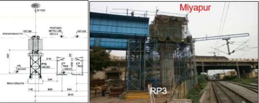
Bharath Nagar ROB Details – Obligatory Span
Location: Bharath Nagar Chainage (Rly Km): 174/22-24 Corridor No: I
Corridor Length: 28.87 Km
Connecting Places: Miyapur to L.B Nagar Obligatory Span Length: 65m
Sub Structure Type: Open Foundations
Size of Substructure: Foundation 12.5m x 7.1m Pier 2.2m x 2.2m
Super Structure Type: Precast Pre-stressed
Fig. 11: Bharath Nagar ROB Details – Obligatory Span
Size of Segment: 8.80m Top Width 4.25m Bottom Width
4.30m Deep
Segment Width: 3.00m No. of Segments (Main Span): 21
Max. Wt. of Segment: 58 MT
Bearing Type& Capacity: POT – PTFE
Preliminary Works
Stage 1
Fig. 12: Preliminary Works
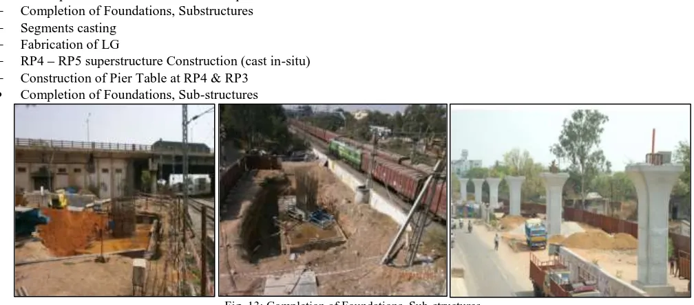
Works completed before construction of Super Structure over RAILWAY SPANS: Completion of Foundations, Substructures
Segments casting Fabrication of LG
RP4 – RP5 superstructure Construction (cast in-situ) Construction of Pier Table at RP4 & RP3
Completion of Foundations, Sub-structures
Fig. 13: Completion of Foundations, Sub-structures
Fig. 14: Super Structure Casting , curing & stacking at pre-cast yard
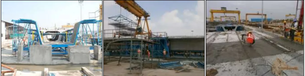
Fabrication of LG with required length and capacity
Fig. 15: Fabrication of LG with required length and capacity
Launching Girder (LG) Details
Dimensions
Length of LG: 117m No. of Modules: 13 Weight of LG: 265 MT Width of LG: 2m each Depth of LG: 3.0m
Live Load: 125 MT (Inclusive of Two segment wt.) No. of Over Head Gantry's: 2 no's
Capacity of each OH Gantry: 75 MT Self-Weight of Gantry: 60 MT
Construction of Pier Table at RP3 & RP4
RP4 – RP5 Superstructure Construction (Cast in-Situ)
Fig. 17: RP4 – RP5 Superstructure Construction (Cast in-Situ)
Erection of Launching Girder over Rly Span
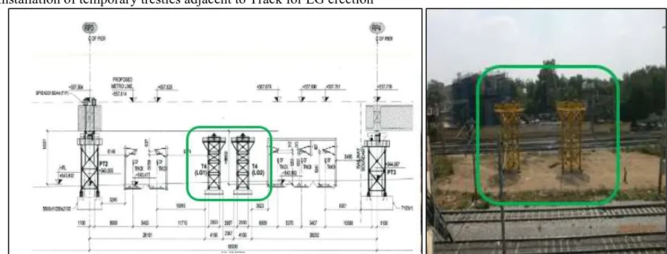
Installation of temporary trestles adjacent to Track for LG erection
Fig. 18: Installation of temporary trestles adjacent to Track for LG erection
Moving and placing of LG over Rly Span
Fig. 20: Plan Showing Both LG in Final Position
Fig. 21:
Fig. 23: Typical Section Showing Hilman Roller
Erection of Overhead Gantry over LG
Fig. 24: Erection of Overhead Gantry over LG
Fig. 25: Joining/Matching of erected Segments
Fig. 26: Stressing of Erected Precast Segments
Fig. 28: Satellite Image Showing the Completed Span Segments over Railway Span at BHARATH NAGAR ROB at Hyderabad Metro Rail Project
Note
With the real-time monitoring of the bridge, the project team was able to correct the support reactions, keep the applied patch-loads within the accepted limits, and properly adjust the vertical support positions during launching, allowing the successful completion of the complex erection process.
Table – 2
Total duration to complete 3-span continuous structure for this location was 2 years & 3 months. There was a considerable delay for about one year from the ‘South Central Railway’ for approval of design & giving traffic block during launching and de-launching. Now the stretch is ready for a trial run with almost accomplishment of civil, track OHE & signaling work.
V. CONCLUSION