Telemetry, Tracking And Commanding (TTC)
Operations Of Nano Satellite
Dinesha H. A, H. N Bhagavan, Dr. V. K Agrawal
Information Science and Engineering Crucible of Research and Innovation Information Science and Engineering PESIT, Bangalore, India-560085 PESIT, Bangalore, India-560085 PESIT, Bangalore, India-560085
[email protected], [email protected], [email protected]
ABSTRACT: PES Institute of Technology along with five other institutions is developing a nano-satellite for capturing images of the earth. The project is intended for students to understand and work with advanced space technologies. The satellite is built around subsystems such as, Attitude Control Sys-tem, Electrical Power System and Mechanical Systems. The data distribution is handled by an On Board Computer (OBC) system which is interfaced to all the subsystems. On Board Computer is a microprocessor board where satellite software is executed. The OBC, after internal processing of satellite telemetry parameters sends the telemetry information using S-band transponder to the ground station. The telemetry information is received by a com-puter system through the ground station setup for receiving the satellite data. This paper, discusses the development of software which is used in the satellite control centre for carrying out TTC operations of satellite. The data is presented to the spacecraft operational personnel using graphics tools for further analysis of the spacecraft health. The design of ground station software is presented in this paper. We use the approach of component-based software methodology.
Keywords : Component-based, Ground Station, On Board Computer, Telemetry Tracking Commanding, Nano Satellite.
1
I
NTRODUCTIONTHE prime endeavour for the construction of the nano satellite is to introduce the learning opportunity to the students through space technology. Thus the students are exposed to the skills of developing the satellite through different phases of analysis, design, fabrication, testing and operations. The major scope of this satellite is to capture the pictures of earth and send to the ground station. It is prepared to launch the satellite in a polar sun synchronous orbit at an altitude of around 650 km and inclined at an angle of about 99º. The orbital period is around 90 minutes; eccentricity is about 0.001 and semi major axis of about 7000km. The launch vehicle used for this purpose is a Polar Satellite Launch Vehicle (PSLV). The hardware compo-nents used are magnetic actuators, magnetometer, power sensors, sun sensors, thermistors, receiver, transmitter, cam-era and solar panels. The processor used here is UT32UC3A0512, which is of 32 bits, 512Kb memory and speed of 1.49 DMIPS (Dhrystone MIPS)/MHz which is neces-sary to achieve our mission. We are concerned with the devel-opment of software which is used in the satellite control centre for carrying out Telemetry tracking and Telecommand opera-tions of satellite. The data is presented to the spacecraft op-erational personnel using graphics tools for further analysis of the spacecraft health. The design of ground station software is presented in the later section of this paper. We used the ap-proach of component- based software methodology to adopt the plug and play feature to the software. In this paper we have elaborated on the ground station configuration of the sat-ellite which is described in section II. The system design of the same is structured in section III. Section IV describes imple-mentation of ground station software. Finally, the paper is con-cluded in section V.
2
G
ROUNDS
TATIONC
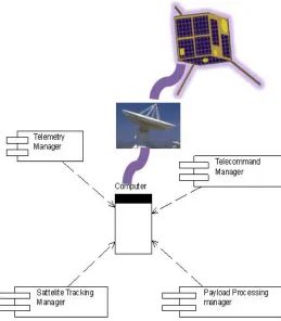
ONFIGURATIONFig. 1 Schematic Diagram of Spacecraft Ground Station
3
S
YSTEMD
ESIGNThis section describes the design methodology of the ground station. This includes each subsystem component wise re-quirement specification, High level design and detailed design document. The role of the major software systems to be de-ployed to handle the entire activity of SCC and earth station is described here. This system is classified according to the spective functions namely, i) Telemetry data reception, re-cording, processing, status (subsystem health) monitoring, alarm reporting and data retrieval feature for offline applica-tion.(Telemetry Processing) ii) Spacecraft commanding (Tele-command) manual or auto commanding, CMD history mainte-nance and CMD status monitoring & alarm reporting. (Tele-command Control) iii) Spacecraft tracking in Auto/Drive mode and range data reception and storing in file and retrieval sup-port at later use (Satellite Tracking). iv) Payload data acquisi-tion and storing and image display in offline (Payload Process-ing). These are pictorially described using the use case dia-gram in figure 2.
i) Software Components and its elements
The software system is classified as: i) Telemetry Data Man-ager ii) Telecommand ManMan-ager iii) Tracking Data ManMan-ager iv) Payload Data Manager. Each of these managers performs most common activities, like Data Acquisition, Archival, Pre-processing, Distribution and Display (presentation). Along with these the TC Manager would take up an additional responsibil-ity of commanding the satellite. The Tracking manager has an antenna driving capabilities for pointing to the satellite. How-ever, payload data Manager would perform a minimum data processing to display the raw images.
Fig. 2 Use case diagram of ground station software
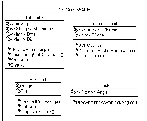
Fig.3 Component diagram of ground station software
3.1 Telemetry Data Manager
The telemetry data manager is responsible for obtaining the Onboard Telemetry data at the ground station. The demodula-tion and frame synchronizademodula-tion of the data is performed by the ground station equipment-Telemetry Interface Unit (TIU). This data is time stamped with the Ground Receive Time (GRT)
Fig 2 . Usecase Diagram of Ground Station Software Telemetry Processing
Telecommand Control
Satellite Tracking
Small Sattelite
play module of the system. The “TM data Archival” s/w does some validation creates pass-wise TM data file and maintains a brief pass history file. Further, the “Real Time TM data proc-essing” software does the EU conversion and updates the Pa-rameter values in the shared memory. This data is distributed to the entire connected client machines by the processed “TM data server” software. The “Page Display” software displays the data on the terminal in formatted pages and the “Real Time Graphics” (RTG) software plots the data .The following section will describe about the task wise breakage of this software system. TM Data Manager consists of the software elements used for : i) TM Data Acquisition, ii) TM Data Archival, iii) TM Data Processing, iv) Real Time Page display, v) Real Time Graphics, vi) TM Data Server, vii) Parameter Table Manager, viii) Page Table Manager, ix) TM Data Retrieval Library, x) Event Recorder and xi) Event Data Offline Display.
3.2 Telecommand Manager
Through the uplink, the command is operated at the spacecraft level and its confirmation status is transmitted through the te-lemetry. This operation is managed by the telecommand man-ager. Besides controlling & operating the spacecraft for obtain-ing the status of the onboard subsystems some commands are uplinked from the earth station. The following section will describe about the task wise breakage of this manager. Tele-Command (TC) Manager Software Elements is used for: i) Tele-command Execution, ii) TC Data Acquisition, iii) TC Data Archival, iv) TC History Display, v) Software SOE. It also per-forms the activity of a tele-command directory manager and TC data retrieval library.
3.3 Tracking Data Manager
Tracking is the prime activity at the SCC to locate the space-craft and control the position of the ground station, antenna to acquire TM data from spacecraft. It is also used to uplink the tele command to the spacecraft and downloads the payload data without any intervention during the pass. The following section will describe about the task wise breakage of this soft-ware system. The function of the tracking manager is to inter-face with the antenna to provide the look angles for tracking the satellite. Tracking Data Manager consists of the software elements used for i) Tracking Data Acquisition ii) Antenna Pro-gram Drive iii) Antenna Auto Drive iv) Tracking Data Archival, v) Tracking data History Display and vii) Tracking Data Re-trieval Library.
Megapixel CMOS Digital Image Sensor with resolution 2,048 x 1,536 pixels. The special feature of the camera is Digital Clar-ity™, Image sensor technology with high frame rate, window-ing capability, auto focus, snap short mode, Skip and Bin Modes and Smaller Format Resolution (QXGA to UXGA, SXGA, XGA, SVGA, VGA, CIF, QVGA, QCIF, etc). During the pass the image data is captured and recorded in the onboard memory and downloaded at a convenient time at a subse-quent pass. The onboard system has the capability to store 2 to 3 scenes of data in the onboard memory. In the onboard, data is compressed in JPEG format and recorded. During the down loading of image, data is received at the earth station and transmitted via RS232 link to the spacecraft control cen-tre. At the control centre the data is acquired and stored in the file system in a systematic way for further use. Also proper backup and restoring operation and housekeeping operations are carried out using software which is completely managed by the Payload Data Manager. Payload Data Manager con-sists of the software elements used to: i) Payload Data Acqui-sition and ii) Quick Look Display The figure 4 shows the class diagram of the ground station TTC software
The software is designed to provide a Graphical user interface in an interactive mode. The menu driven GUI system can fa-cilitate the user to select the sub system page through the click of button. Following figure provides the conceptualization of the layout of the Health Monitoring system which consists of the identified pages. Fig 5 shows the GUI layout which has all the software components for users whereas Fig6 shows the GUI layout only for the commanding component.
Fig-6 Description of the command code display
Fig-6 Description of the command code display
4
I
MPLEMENTATIONThis section describes the implementation algorithms for te-lemetry processing and telecommand control software. It also presents the typical output screenshots of the software mod-ule. Wherever components were not ready, stub modules were used for integration and testing. Requirement traceability met-rics is being maintained for design, implementation and test-ing. Simulated data with all possible expected error conditions incorporated in test data have been used for testing the soft-ware. System load computation and system performance analysis is carried out.
4.1 Algorithms
1. Telemetry Processing
Step 1: [Read the incoming frame from the receiver] Receiver->Decoding->Digital Signal->Data Conversion->RS232->PC
Step 2: [Archival: Store the frame in file] Step 3: [Extract the data from frame] Specific_Bits(Frame)
Specific_Bytes(Frame)
Step 4: [Engineering unit conversion as per database] Step 5: [Send to display Screen]
2. Telecommand Control
Step 1: [Select the command] Step 2: [Validate the command] Step 3: [BCH Coding]
BCH Coding:
BCH coding can be explained in the following steps:
For any integer m ≤ 3 andt< 2m-1 there exists a primi-tive bch code with following parameters :
o n=2m -1
o n-k ≤mt
o dmin≥2t+1
This code can correct ‘t’ or few random errors over a span of 2m-_1 bit positions.
o The code is a t-error correcting BCH code.
For example, consider m=6, t=3
o n = 26-1 = 63
o n-k=6x3=18
o Dmin=2x3+1=7
Hence the code would be (63,45).
o Which explains that the codeword length is 63
o Generated parity bit length = 63-45 = 18 bits
o We assumed t=3, hence this code can detect and correct 3 error bits.
Step 4: [Prepare Command Bit pattern]
Step 5 : [Send command to the ground transmission system
CMD CODE File Name
ONBOARD CMDREG Transmitted
for sending to satellite]
4.2 Typical output (Software Screenshots)
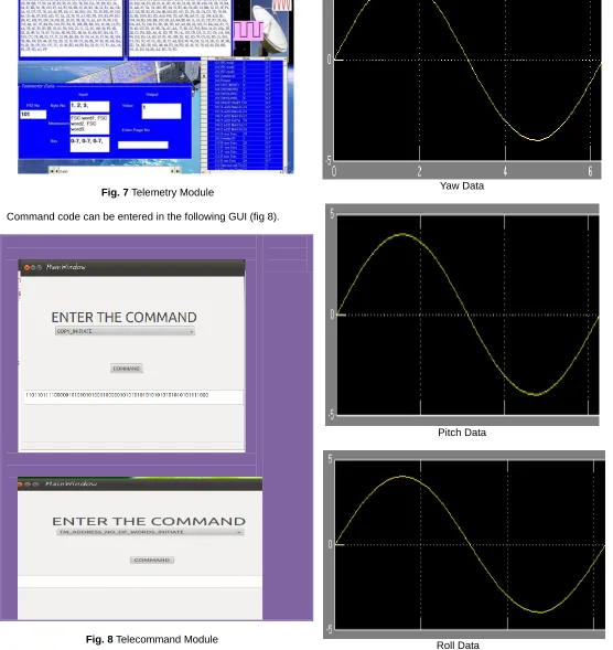
The fig 7 captures the incoming raw telemetry data and latest valid frame of data is shown.
Fig. 7 Telemetry Module
Command code can be entered in the following GUI (fig 8).
Fig. 8 Telecommand Module
The real time plot is illustrated below. The parameters to be plotted as well as the time scale are selectable ( fig. 9)
Yaw Data
Pitch Data
Roll Data
ing corresponding database. Costeffective, userfriendly and optimized software with userfriendly interface has been im-plemented and it serves as a guideline for future nano-satellite missions. The feedback from the operation teams is used for further improvement in the existing software.
A
CKNOWLEDGMENTOur sincere thanks to Prof. K N B Murthy, Principal and Prof. Shylaja S S, HOD, Department of Information Science and Engineering, PESIT, Bangalore, for their encouragement