Vol. 05, Issue 03 (March. 2015), ||V1|| PP 11-15
International organization of Scientific Research 11 | P a g e
Analysis of A 2-Phase Stator Winding By Winding Function
Methodology
*
I.K.Onwuka,
**U.U.Uma,
*G. C. Diyoke
*
Michael Okpara University of Agriculture, Umudike, Nigeria. [email protected]
**
AkanuIbiam Federal Polytechnic, Unwana, Nigeria.
Abstract:A two-phase stator winding is presented here and analyzed. By two-phase, it is implied that the two stator windings are identical and displaced in phase by 90 degrees, and can supply single-phase loads from either terminal. First, a stator winding was presented for a specified stator, and the winding distribution analyzed with the aim of obtaining the mmf characteristics from its functional relationship with the winding function.The particular stator winding presented in this work was found to be with low mmf harmonic level, and would perform acceptably when it forms part of an ac machine, typically, a generator of induction or reluctance type in the low power range.
Key words:Two-phase, Winding function.
I. INTRODUCTION
With the world’s growing interest on reducing greenhouse effect and boosting power supply to urban and remote areas, intensive research is in the area of determining practical electromechanical conversion devices in both the low and high power ranges for easy and efficient conversion of energy from unconventional energy sources to electricity. At the low power range, such devices are required to be rugged, near maintenance free, affordable, and uncomplicated, and providing good quality of power.Along this line, extensive work has been done on single phase and three phase generators of induction and reluctance types. Self-excitation of these generators is achieved by the action of capacitors connected to the terminals of the machine. For example, [1] discussed the performance prediction and analysis of a single phase self-excited induction generator excellently. Also, [2] presented a mathematical model by which the dynamic behavior of self-excited single-phase reluctance generator can be successfully predicted under different operating conditions, while [3] was minded of the steady state analysis of the same. Plenty research results are also available in three-phase autonomous reluctance generators in both the dynamic and steady-state concerns[4, 5, 6]. Generators in the low power range are usually single-phase machines and are usually two-winding machines having a main winding and an auxiliary winding. However, less is considered of two-phase machines.
By 2-phase stator winding, it is implied here that the machine is able to supply single phase loads from the two stator terminals, with a phase difference of 90o. The analysis employed is akin to asynchronous stator winding which has a main and an auxiliary winding, of which the former has more number of turns of conductor than the latter and occupies about two thirds of the stator slots [7]. The current in both windings are displaced by an angle of 90o. The basic difference is that the windings in this work are of equal number of turns, and occupies equal number of stator slots. Such stator winding arrangement readily find application in autonomous production of electricity through renewable and non-conventional energy sources.A good design will aim to realize a sinusoidal stator mmf wave form with minimum harmonic content. Minimizing the stator mmf harmonic contents is of great importance for many reasons, including minimizing voltage and current harmonics [8]. Stator losses are also reduced. The focus of the present work is to suggest a stator winding arrangement with clear analysis, showing a sinusoidal stator mmf with reduced harmonics, of a two-phase machine. The interest is restricted to terminal rather than internal characteristics of the machine.
Specification
It is intended to obtain a stator winding design for a 1hp, 220V, 2-pole, 2-phase machine.
II. MACHINE DIMENSIONS
With the methods suggested by [7] and [9], the dimensions of the stator can be determined to meet the above specifications, with a few assumptions with respect to specific magnetic and electric loading of the machine. These are considered the main dimensions of the machine. It will be observed however, that this is a different research focus from the present endeavor.
International organization of Scientific Research 12 | P a g e
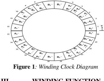
A double-layer, integral-slot winding with chorded coils will be used. Taking 12 slots per pole, the stator number of slots is 24. Each slot holds 18 conductors, which could be of either or both phases. Windings were distributed as near sinusoidal as possible. References here include [7, 8, 9]. Furthermore, the windings of both phases are identical but displaced from each other by an angle of 90o.The winding clock diagram appears in figure 1.The following can easily be observed from the winding clock diagram:
Number of slots = 24; Slot angular pitch = 15o; Phase belt = 10 slot pitch; Phase spread = 150o; phase shift = 90o; Number of poles =2; Pole-pitch = 12 slots per pole.
Assumption
Each winding section is aligned axially within the air gap. This is to say that the wire is neither slanted in the circumferential direction nor tilted in the radial direction as it passes through the air gap.
A1+
A2+
A3 +
A4+
A5+
A5 –
A4 –
A3 –
A2 –
B2 – B2 +
B3 +
B4 +
B5 +
B3 –
B4 –
B5 –
1 2 3 4 5 6 7 8 9 10 11 12
A1 –
B1 – B1 –
φ
A1+
A2+
A3 +
A4+
A5+
A5 –
A4 –
A3 –
A2 –
B2 – B2 +
B3 +
B4 +
B5 +
B3 –
B4 –
B5 –
24 23 22 21 20 19 18 17 16 15 14 13 A1 –
B1 – B1 –
Figure 1: Winding Clock Diagram
III. WINDING FUNCTION
[10] observed that the knowledge of the winding functions for all windings together with the winding current essentially describe the spatial field distribution in the gap of the machine. Moreover, it is well known that the winding function is the basis of calculating machine inductances. Obviously, the harmonic
Table 1: The A and B-phase stator turns and winding functions
S/No
s a
n
Coil spann
avaN
as
sn
b
sCoil span
avb
n
N
bs
s1 6
12
23
6
5.250 0.750 1212
11
6
4.500 7.52 9
6
11
4
7.125 1.875 912
10
4
2.625 6.3753 9
4
7
3
6.375 2.625 94
3
3
1.875 7.1254 12
6
10
12
5
7.500 4.500 63
2
12
5
0.750 5.2505 18
12
19
2
9.750 8.250 012
7
2
0 06 18
2
3
12
7
8.250 9.750 02
7
12
19
0 07 12
12
17
3
2
4.500 7.500 612
41
3
5
5.250 0.7508 9
3
4
4
3
2.625 6.375 93
10
4
International organization of Scientific Research 13 | P a g e
9 9
4
5
6
5
1.875 7.125 94
13
6
11
6.375 2.62510 6
6
7
12
11
0.750 5.250 126
19
12
23
7.500 4.50011 0
12
13
0 0 1812
37
2
9.750 8.250
12 0
2
12
0 0 18
12
8.250 9.750
108
n
a
s
n
ava
54
N
as
s
54
n
b
s
108
n
avb
54
N
bs
s
54
content of both stator voltage and current depend on the shape of the air gap mmf due to the stator windings. Hence, stator winding analysis based on winding function is presented here. Equation (1) represents the relationship between the air gap mmf, the winding function, and the stator current. Subscript “s” represents stator quantity, and Ns the winding function.
𝑚𝑚𝑓𝑠= 𝑁𝑠
2 𝑖𝑠𝑐𝑜𝑠𝜙𝑠 (1)
Where φs is an angular displacement along the stator inner circumference. The winding function (WF)
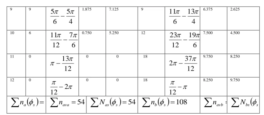
methodology developed in [11] was employed in this analysis. Table 1 shows the turns and winding functions for both windings, where n(φs) and nave are the turns function and the average turns function respectivley, given
by:
𝑛 𝜙𝑠 = 𝑁𝑜. 𝑜𝑓𝑡𝑢𝑟𝑛𝑠𝑖𝑛𝑖𝑛𝑡𝑒𝑔𝑟𝑎𝑡𝑖𝑜𝑛𝑝𝑎𝑡 (2)
𝑛𝑎𝑣𝑒 = 1
2𝜋 𝑛 𝜙𝑠 2𝜋
0 𝑑𝜙𝑠 (3) The winding function is then given by:
𝑁𝑠 𝜙𝑠 = 𝑛 𝜙𝑠 − 𝑛𝑎𝑣𝑒 (4)
Together with the information under the Winding Description, these equations were adjusted to develop Table 1, integrating over the span specified.
Also, figure 2 and 3 shows the actual winding function, in stair-case form. These can also be deduced from Table 1.
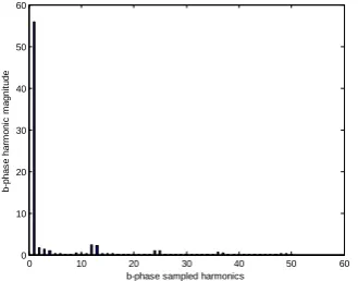
Harmonics Analysis
The method of Fourier series [12] was applied to obtain the various harmonics present in the winding functions expressed in Figures 2 and 3. The Fourier series of the winding function was performed and various plots obtained using the MATLAB tool [13]. The fundamental components of the winding functions for the two stator windings are:
𝑁
𝑎𝑠= 𝑁
𝑠𝑐𝑜𝑠
𝜙
𝑠− 𝛿
(5)
𝑁
𝑏𝑠= 𝑁
𝑠𝑠𝑖𝑛
𝜙
𝑠
− 𝛿
(6)
Where, δ is the phase shift, and subscript s refers to stator variables.
Figures 4 and 5 give a picture of the harmonic contents in the winding function, up to the 50
thInternational organization of Scientific Research 14 | P a g e
Figure 2: Actual Winding function of the a-phase winding
Figure 3:Actual Winding Function of the b-phase winding
Figure 4:Harmonics of the a-phase winding function
Figure 5:Harmonics of the b-phase winding function
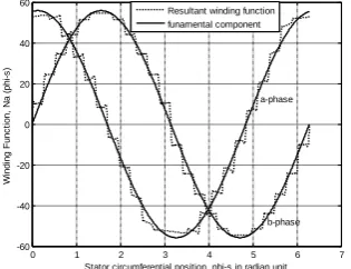
A comparison between the resultant winding function (sum of all the harmonics including the fundamental component) and the fundamental component of the winding function, shown in figure 6, reveals that the approximation of the fundamental component to the resultant winding function is quite close.
Hence, this can be used for inductance calculation of the machine. This plot is found identical for the two phases, except that they are displaced in phase by 90o. It is observed that the fundamental component is same for both windings, with the following phasor value:
0 1 2 3 4 5 6 7
-60 -40 -20 0 20 40 60
Stator circumferential position, phi-s in radian unit
W
in
d
in
g
F
u
n
c
ti
o
n
,
N
a
(
p
h
i-s
)
0 1 2 3 4 5 6 7
-60 -40 -20 0 20 40 60
Stator circumferential position, phi-s in radian unit
W
in
d
in
g
F
u
n
c
ti
o
n
,
N
b
(
p
h
i-s
)
0 10 20 30 40 50 60
0 10 20 30 40 50 60
a-phasesampled harmonics
a
-p
h
a
s
e
h
a
rm
o
n
ic
m
a
g
n
it
u
d
e
0 10 20 30 40 50 60
0 10 20 30 40 50 60
b-phase sampled harmonics
b
-p
h
a
s
e
h
a
rm
o
n
ic
m
a
g
n
it
u
d
International organization of Scientific Research 15 | P a g e 𝑁𝑎𝑠= 55.8254∠ − 0.1309𝑟𝑎𝑑 (7)
𝑁𝑏𝑠= 55.8254∠1.4399𝑟𝑎𝑑 (8)
If the close approximation of the fundamental harmonic to the resultant winding function is accepted as the eventual winding function, then the effective number of stator turns will be taken as Ns = 55.8254. It is clear
that the influence of winding design features which have not been considered in the analysis are accounted for in Ns.
Figure 6:Comparison between the resultant winding function and the fundamental component of the function.
IV. CONCLUSION
It must be observed here that saliency has no influence on the form of the winding function [10], so that the stator winding here realized can be adapted to a round-rotor or a salient-pole machine. The particular design of the stator winding presented in this work suggests minimal current and voltage harmonics. Also, the analysis here presented shows that with little loss of accuracy, the fundamental component of the winding function can be adopted for inductance calculation of the machine. Again, it is clear that the two-phase stator presented in this work will perform acceptably when it forms part of an electric machine, typically, a small generator. As earlier mentioned, this generator could be of induction or reluctance type. It is therefore presented here that a two-phase ac generator of various power ratings can be designed and used for domestic and certain farm processing activities in the low power range. The authors think this will lead to a better utilization of the stator slots.
REFERENCES
[1]. Bhim Singh et al, “Improved Steady State and Transient performance with optimum excitation of Single-phase self-excited Induction Generator”, Electric Machines and Power Systems, 28:591-604, 2000.
[2]. S.M. Allam, M. A. El-Khazendar, and A.M. Osheiba. Dynamic analysis of a self-excited single-phase reluctance generator, ElectricPower Components and Systems, 34:725-738, 2006.
[3]. J. Chen and P. Famouri. Single-phase self-excited reluctance generator, part I: Steady-state analysis, Electr. Power ComponentSystems, vol. 31, pp. 129-147, 2003.
[4]. Ben-Hail, N., and Rabinovici, R., “Three-phase autonomous reluctance generator”, IEEE Proc. Elect. Power Appl., Vol. 148, No. 5, pp. 438-442, September 2001.
A. K. Tandon, S. S. Murthy, and G. J.Berg. Steady-state analysis of capacitor self-excited induction generators, IEEE Transactions on Power Apparatus and Systems,vol. PAS-103, no. 3, pp. 612-618, March1984.
[5]. T. F. Chan. Steady-state analysis of a three-phase self-excited reluctance generators, IEEE Transactions on Energy Conversion, vol. 7, no. 1, pp. 223-230, March 1992.
[6]. Mittle, V. N., and Mittal A., “Design of Electrical Machines”, Standard Publishers Distriibutors, Delhi, 2006. [7]. Paul C. Krause, Oleg Wasynczuk, Scott D.Sudho_. Analysis of Electric Machinery,IEEE Press, New York, 1995. [8]. JuhaPyrhonen, TapaniJokinen, Valeria Hrabovcova, “Design of Rotating Electric Machines”, John Wiley and Sons
Ltd, 2008.
[9]. P. S. Bimbhra, “Electrical Machinery”, Khana Publishers, Delhi, Seventh Edition, 2008.
[10]. Obe, E. S. Nnadi, D. B and Eke, J. Inductances and Airgap Flux density of aSynchronous Reluctance Machine using theActual Machine Geometry, NSE TechnicalTrans. Vol. 44. No. 4, pp.49-63, 2009.
[11]. Erwin Kreyszig. Advanced EngineeringMathematics, John Wiley and Sons, Inc,New York, 1979. [12]. MATLAB. Mathworks2007 :Natic, Pennsylvania, USA.
0 1 2 3 4 5 6 7
-60 -40 -20 0 20 40 60
Stator circumferential position, phi-s in radian unit
W
in
d
in
g
F
u
n
c
ti
o
n
,
N
a
(
p
h
i-s
)
a-phase