© 2017 IJSRST | Volume 3 | Issue 4 | Print ISSN: 2395-6011 | Online ISSN: 2395-602X Themed Section: Science and Technology
Performance Analysis of MIMO FSO Link Employing Different Modulation
Techniques
Harjeevan Singh, Gurdeep Singh
Department of ECE, CU, Gharuan, Punjab, India
ABSTRACT
The susceptibility of Free Space Optics (FSO) towards atmospheric attenuation has introduced the need of MIMO systems in FSO system as the finest solution. This technology can be an alternative backup to already established broadband technology, so a proper understanding has become very important in order to establish a MIMO FSO link effectively. This paper gives the prelude results of the FSO link performance with multiple transmitters and receivers operated under different modulation schemes such as PAM, QAM, DSPK. The response of MIMO FSO using these modulation techniques was then compared in terms of maximum achievable BER .
Keywords : FSO, MIMO, DPSK, PAM, QAM, Atmospheric Turbulence, Eye Diagram, Transmitted Power.
I.
INTRODUCTION
The free space optics (FSO) communication system is a line of sight based technology that transmits a visible or infrared light modulated beam through the atmosphere for broadband communications. Basically the concept is that a narrow beam of light carrying a optical signal generated at transmitter station is transmitted through the atmosphere which is received at the receiver station. This technique needs a clear line of sight between transmitter and reciever. This technology is referred as “optical wireless” or “fiberless optics” transmission since it gives the speed of fiber with the flexibility of wireless.
The advantages of FSO system over the conventional system are that it requires no licensing for frequency spectrum and the immunity to radio frequency saturation has added security features in this technology. It is very difficult to tap or jam the FSO link due to its narrow beam angle for several maradians. Environment wise, FSO does not pollute it with electromagnetic radiation. The commonlt used wavelength range for FSO is between 850 nm and 1550 nm and its best feature is the cost reduction of system. With the usage of laser and easy deployment of wireless link it is faster and cheaper as compared to the optical cables.
In spite of all the compensation, FSO link performance is degraded by the atmospheric phenomena. As the
medium of propagation for optical signals is troposphere, so it is greatly affected by atmospheric phenomena. Since the FSO is LOS based, these phenomena greatly affect the link performance. The performance gets worst with increment in the transmitter-receiver distance. Moreover, the climatology and the physical characteristics of the installation location also affects the performance of the FSO. Commonly the FSO system using single transmitter and receiver is used to transmit the optical signal but it is possible to incorporate more than one transmitter and receiver to improve the performance of FSO link. This work proposes the idea of multiple Transmitter/Receiver for the terrestrial FSO link.
II.
SYSTEM OVERVIEW
As shown in the Fig 1. we use multiple transmitters at the transmitting end and multiple receivers at the receiving end. Each terminal consists of a link head which further consists of multiple lenses of transmitters and receivers. They will collect and produce the multiple laser beam. These multiple beams are independent beams when they leave the transmitter unit but over the distance they began to overlap with each other, at the time they reach the receiver they become a single beam. The length of channel can be decided according to the requirements of the system.
In this system the redundant signals are generated by the data splitter. They splits the data signal into four independent signals, each carries the same data input. Then these signals are transmitted by spatially diversed transmitters labelled as TX1, TX2, TX3, TX4. Hence each transmitter will send an independent signal to receiver labelled as RX1, RX2, RX3, RX4.
Figure 1. MIMO System[1]
The maximum number of Transmitter/Receiver taken in this work are four, because of taking cost factor and system complexity into consideration. The cost of our system will get increased if the number of transmitters and receivers are increased.
I. SYSTEM MODELING
MIMO system is modelled for a FSO link using Optisystem 7.0 by Optiwave. Fig. 2 shows the layout of the four Transmitter/Receiver Combinations. A typical system consist of a transmitter, a channel and a receiver.The frequency of the transmitter is set to be 193.1 THz and the attenuation is 12dBm . The other parameters are such as Given in Table 1.
TABLE 1
SYSTEM AND LINK PARAMETERS Transmitter Power (mW) 5dbm -7dbm
Frequency (Thz) 193.1
Transmitter Aperture 2.5
(cm)
Beam Divergence (mrad) 2
Reciever Aperture (cm) 8
Atmospheric Attenuation (db/km)
12
Maximum Link Range (metres)
1000
Receiver Sensitivity (dBm)
-45
Receiver Aperture (cm) 8
Transmitter Losses (dB) 1.8
Receiver Losses (dB) 1.8
Photo Detector Used PIN
The transmitter is connected with the element fork to duplicate the number of output ports, so that each signal coming out is having same value with the ouptut signal from
the previous component. The first fork connected to the TX will produce the multiple laser beams. Then the beams are combined with the power combiner before sending to the FSO channel.
The output signals coming out of the power combiner travel through the atmoshere and reach receiver unit. The aperture of the Transmitter and Receiver are set to be 2.5 cm and 8 cm respectively. The beam divergence is 2 mrad and the link range distance is 1 km. The theoretical model used for the FSO channel equation is asin the Eq. (1) which is suitable for the single Transmitter/Receiver system. Hence, the work will involve the modification to multiple system from single system.The received power is defined as :
PR=PT×
×10
αR (1)
Where PR is recieved power(dB) at the reciver, Pt is the
for any laser power is in a form of exponential equation of which has been described as follows:
Latm=e -𝜎l
(2)
Where l (km) is the transmittance range of the laser and Q is the typical attenuation coefficient (0.1 for clear air). Since the work is considered in the turbulent weather condition, the attenuation is set to be 12 dB/km. All the signal coming out of FSO channel are fed to the power combiner before received by the Receiver. The sensitivity of the reciver is set to be -45 dBm. The BER analyser and the optical power meter are used to analyse the results. From the BER analyser, we can see the BER performance of MIMO FSO in terms of eye diagram. The bit rate used in the system is the 1Gbps.
Figure 2. Schematic of MIMO FSO using Mach Zehnder Modulator
The system discussed above is simulated using the simulation parameters for different modulation techniques. As shown in Fig. 2,the MIMO FSO system using mach zehnder modulator has been used. MIMO system consisting of four transmitters/receivers has been used. The system is simulated under different modulation techniques. The modulation techniques considered in this work are DPSK,PAM,QAM,PAM (MZ).
For different modulation schemes all the factors discussed are taken as same, and the BER is calculated with respect to the transmitted power. By increasing the transmitted power the respective BER is analysed with BER analyser. The output of BER analyser is in the form of eye diagrams, that will give the idea about the system performance. Along with the BER, the received power and the Q factor is also calculated. So the BER
analysis of all the modulation techniques has been done by varying input power and channel attenuation.
III.
RESULTS AND DISCUSSIONS
The system deccribed above has been simulated using given parameters.The BER performance analysis of various modulation techniques has been done by varying input power and FSO channel attenuation. The results have been discussed as :
A. Analysis of BER performance by varying input power
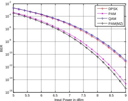
The BER analysis of various modulation techniques has been done by varying input power from 5dBm to 9 dBm.
Figure 3. BER analysis by varying input power
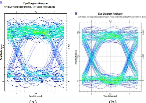
As shown in fig. 3 it is clear that by varying input power, the BER performance is improving. The improvement in BER performance of PAM using Mach Zehnder Modulator is more as compared to other modulation techniques. Hence we can say that MIMO FSO employing PAM (using Mach Zehnder Modulator) gives better BER performance as compared to other modulation techniques.The eye diagram for DPSK and PAM (MZ) has been shown in fig. 4.As we can see the eye opening in case of PAM (MZ) is more as compared to DPSK.
5 5.5 6 6.5 7 7.5 8 8.5 9
10-16 10-14 10-12 10-10 10-8 10-6 10-4 10-2
Input Power in dBm
BER
(a) (b)
Figure 4. Eye diagrams: (a) DPSK (b) PAM (MZ)
B. Analysis of BER performance by varying channel attenuation
The BER performance of MIMO FSO has been analyzed by varying channel attenuation from 12 dB/Km to 17 dB/Km. This analyis has been done for various modulation techniques like PAM(using MZ), DPSK, PAM, QAM. As it is clear form fig. 5 that as the channel attenuation is increasing, the BER performance is degrading. It has been observed that if the channel attenuation is increased,the BER performance of PAM using Mach Zehnder modulator is better as compared to other modulation techniques. The eye diagram for QAM and PAM (MZ) has been shown in fig. 6
Figure 5. BER Performance Analysis by varying channel attenuation
(a) (b)
Figure 6. Eye Diagram: (a) QAM (b) PAM (MZ)
The eye opening for PAM (MZ) is more as compared to QAM. So PAM (MZ) performs better even if the FSO channel suffers more channel attenuation.
IV.
CONCLUSION
The aim of this work is to setup and investigate a multiple Transmitter/Receiver FSO link and its performance analysis under different modulation techniques. Analysis of system performance is based on the BER performance. The simulation results show that in case when transmitting power is increased, PAM modulated MZ modulator gives better performance in terms of BER in comparison with the other modulation techniques like QAM, DPSK, PAM. Similarly for the analysis of BER performance by varying the channel attenuation, PAM using MZ modulator gives better BER performance as compared to other modulation techniques and QAM gives worst BER performance.
V.
REFERENCES
[1]. S. M. Metev and V. P. Veiko, Laser Assisted Microtechnology, 2nd ed., R. M. Osgood, Jr., Ed. Berlin, Germany: Springer-Verlag, 1998.
[2]. J. Breckling, Ed., The Analysis of Directional Time Series: Applications to Wind Speed and Direction, ser. Lecture Notes in Statistics. Berlin, Germany: Springer, 1989, vol. 61.
[3]. S. Zhang, C. Zhu, J. K. O. Sin, and P. K. T. Mok, “A novel ultrathin elevated channel low-temperature poly-Si TFT,” IEEE Electron Device Lett., vol. 20, pp. 569– 571, Nov. 1999.
[4]. M. Wegmuller, J. P. von der Weid, P. Oberson, and N. Gisin, “High resolution fiber distributed measurements
12 12.5 13 13.5 14 14.5 15 15.5 16 16.5 17
10-16 10-14 10-12 10-10 10-8 10-6 10-4 10-2 100
Atmospheric Attenuation in dB/km
BER
with coherent OFDR,” in Proc. ECOC’00, 2000, paper 11.3.4, p. 109.
[5]. R. E. Sorace, V. S. Reinhardt, and S. A. Vaughn, “High-speed digital-to-RF converter,” U.S. Patent 5 668 842, Sept. 16, 1997. (2002) The IEEE website. [Online]. Available: http://www.ieee.org/
[6]. M. Shell. (2002) IEEEtran homepage on CTAN. [Online]. Available: http://www.ctan.org/tex-archive/macros/latex/contrib/supported/IEEEtran/ [7]. FLEXChip Signal Processor (MC68175/D), Motorola,
1996.
[8]. “PDCA12-70 data sheet,” Opto Speed SA, Mezzovico, Switzerland.
[9]. A. Karnik, “Performance of TCP congestion control with rate feedback: TCP/ABR and rate adaptive TCP/IP,” M. Eng. thesis, Indian Institute of Science, Bangalore, India, Jan. 1999.
[10]. J. Padhye, V. Firoiu, and D. Towsley, “A stochastic model of TCP Reno congestion avoidance and control,” Univ. of Massachusetts, Amherst, MA, CMPSCI Tech. Rep. 99-02, 1999.
![Figure 1. MIMO System[1] The maximum number of Transmitter/Receiver taken in](https://thumb-us.123doks.com/thumbv2/123dok_us/9100319.1444557/2.595.296.552.50.276/figure-mimo-maximum-number-transmitter-receiver-taken.webp)