National Conference on Advances in Engineering and Applied Science (NCAEAS) 29th January 2018
Organized by : Anjuman College of Engineering and Technology (ACET) Nagpur, Maharashtra, India, In association with
International Journal of Scientific Research in Science and Technology
A Comparative Analysis of the Voltage Profile Stability for the
Wind Farm Using Capacitor Bank and STATCOM
Chandan S. Kamble1, Dipesh Suryawanshi2, Rajni Rewatkar1
1
Assistant Professor, Priyadarshini College of Engineering, Nagpur, Maharashtra, India 2
Assistant Professor, Prestige College of Engineering, Nagpur, Maharashtra, India
ABSTRACT
The performance of the STATCOM reactive power control system is powerful and robust can open the opportunities in the field of renewable energy system to make them more reliable and efficient. Wind generation is currently the major form of new renewable, generation in the world. The active power mainly depends upon the potential of the wind power produced and wind turbine generator design whereas the reactive power demand on the other hand depends upon conversion devices and recovered power quality fed to the grid. The wind farms which accesses to power grid cause fluctuations and reactive power redistribution and sometimes lead to voltage collapse. Similarly, the dynamic voltage stability is a major challenge faced by distribution network operators. The proposed scheme contains modeling of wind turbine DFIG and STATCOM for development of sophisticated control system. Because of uncertainty of wind and environmental condition, monitoring of the voltage profile is done easily.Modeling of wind turbine (DFIG) generation with the control circuitry as to get synchronised with the STATCOM and Capacitor Bank demonstrated using MATLAB/Simulink environment.
Keywords: STATCOM, DFIG, Capacitor ,wind energy
I.
INTRODUCTION
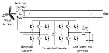
Figure 1.1 presents a topology that consists of a DFIG with AC/DC and DC/AC converters, as a four-quadrant AC/AC converter using isolated gate bipolar transistors (IGBTs) connected to the rotor windings. In the DFIG topology, the induction generator is not a squirrel cage machine and the rotor windings are not short circuited. Instead, the rotor windings are used as the secondary terminals of the generator to provide the capability of controlling the machine power, torque, speed, and
Figure 1. DFIG (Doubly Fed Induction Generator) Topology
from both the rotor and stator sides. The speed and the torque of the wound rotor induction machine can be controlled by regulating voltages from both the rotor and the stator sides of the machine.
II.
MATHEMATICAL MODELLING
In order to achieve the usual modelling of induction machine some of the following assumption has been made.
Effect of slots on machine performance is ignored.
The rotor has symmetrical structure. This enables the identical d-q circuits.
Rotor speed is not fixed and can be varied according to load and the requirement. This may affect the selection d-q reference frame.
There is no excitation source applied in the
rotor winding. Slip is main variable to determine the dynamic of the rotor circuit.
Rotor is modelled as equivalent three phase
winding as it provides the same rotating mmf with respect to the stator only.
Also, core loss is neglected; assumption is made only for available copper loss.
To minimize the complexity stator variable and
parameter are given by Kabc and rotor parameter
and variables are defined using KABC.
Figure 2. Position of rotor flux vector
r instationary reference frame α - β, and synchronously rotating reference frame d-q.
sin
2 sin
3
2 sin
3
a m s
b m s
c m s
v V t
v V t
v V t
(2.1)
sin
2 sin
3
2 sin
3
a m s
b m s
c m s
i I t
i I t
i I t
(2.2)
Rotor axis is shifted by angle θ i.e. rotor axis leads the axis of phase a stator winding.
1
rr s
t
s
(2.3)
As defined earlier that the
r is rotor angularvelocity in rad/s and
sis angular velocity ofstator field in rad/s.
Dynamic equations of induction machine are given as;
a a a a
b b b b
c c c c
v
r i
p
v
r i
p
v
r i
p
(2.4)
In the equation 3.7 the stator dynamics and rotor dynamic equation are given.
d q
* s
* s
v r
c r
r
A A A A
B B B B
C C C C
v
r i
p
v
r i
p
v
r i
p
(2.5)
In equation 2.4 and 2.5 both ; ψ represents the flux linkage in the respective winding, rABC is
the rotor resistance in respective phases. Where, the rabc is the stator resistance of respective
phases.
Here the mutual inductance between the stator and rotor are function of rotor position given in the system. Flux linkage for every stator phase is given, in these the self-inductance (Lss) is
given with the mutual (Lsr) inductance
III.
STATIC SYNCHRONOUS COMPENSATOR
(STATCOM)
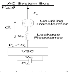
Figure 3.1 shows the basic model of a STATCOM which is connected to the ac system bus through a coupling transformer. In a STATCOM, the maximum compensating current is independent of system voltage, so it operates at full capacity even at low voltages. A STATCOM’s advantages include flexible voltage control for power quality improvement, fast response, and applicability for use with high fluctuating loads. The shunt inverter, transformer and connection filter are the major components of a STATCOM. The control system employed in this system maintains the magnitude of the bus voltage constant by controlling the magnitude and/or phase shift of the voltage source converter’s output voltage. By properly controlling iq, reactive power exchange is achieved. The DC capacitor voltage is maintained at a constant value and this voltage error is used to determine the reference for the active power to be exchanged by
the inverter. The STATCOM is a static VAr
generator whose output can be varied so as to
maintain or control certain specific parameters of the electric power system.
Figure 3. STATCOM Model
The STATCOM is a power electronic component that can be applied to the dynamic control of the reactive power and the grid voltage. The reactive output power of the compensator is varied to control the voltage at given transmission network terminals, thus maintaining the desired power flows during possible system disturbances and
contingencies.
IV.
IMULATION AND RESULTS
Simulation Model:-
Given in figure 4.1 where the wind farm is depicted in the separate unit as shown in figure 4.2. The STATCOM based system has the different advantages as mentioned earlier. As no trip system has been incorporated in the unit to show the error free and no fault condition. However, one can create fault at any of the wind turbine to monitor the effect of the undervoltage, overspeeding, overvoltage and overcurrent.
The system has been modelled and simulated using the SIMULINK/MATLAB 2013a and has been verified for different level of condition.
phase bolted fault for momentary condition. Another case where the system behaves in healthy condition.
Figure 4. Simulation of Wind Turbine Setup with STATCOM
Simulation result:-
Figure 5. Reactive Power Injected at B25 During Healthy Condition
Figure 6. Wind Speed Obtained at Different Wind Turbine
Figure above shows the wind speeds at the different location of the farm as encountered by the different wind turbine.
Figure 7. Wind Speed in [pu] as Encountered by the Respective WT.
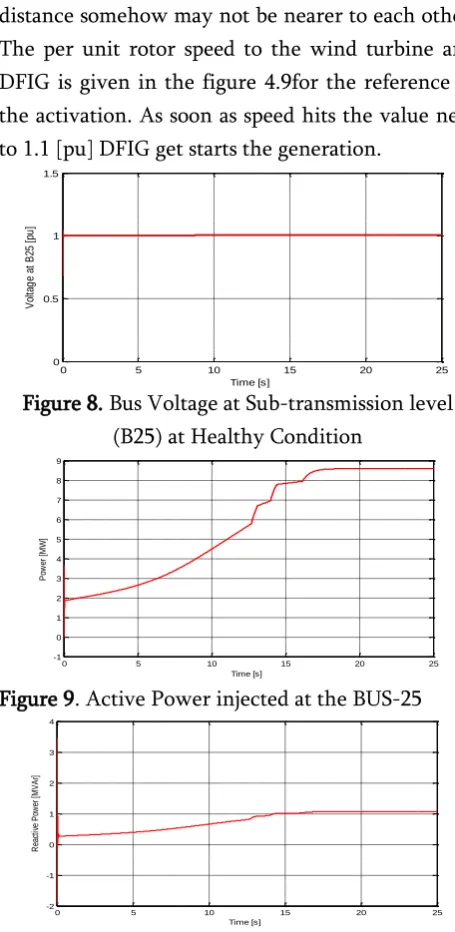
In the system with installation in the same area the distance somehow may not be nearer to each other. The per unit rotor speed to the wind turbine and DFIG is given in the figure 4.9for the reference of the activation. As soon as speed hits the value near to 1.1 [pu] DFIG get starts the generation.
Figure 8. Bus Voltage at Sub-transmission level (B25) at Healthy Condition
Figure 9. Active Power injected at the BUS-25
Figure 10. Reactive Power Injected at the BUS-25
0 5 10 15 20 25
-2 -1 0 1 2 3 4 Time [s] R ea ct iv e P ow er a t B us -2 5 [M V A r]
0 5 10 15 20 25
7 8 9 10 11 12 Time [s] W in d S p e e d [ m /s ] WT-1 WT-2 WT-3
0 5 10 15 20 25
0.7 0.8 0.9 1 1.1 1.2 1.3 Time [s] W in d T u rb in e R o to r S p e e d [ p u ] WT-1 WT-2 WT-3
0 5 10 15 20 25
0 0.5 1 1.5 Time [s] V ol ta g e at B 25 [ pu ]
0 5 10 15 20 25
-1 0 1 2 3 4 5 6 7 8 9 Time [s] P ow er [ M W ]
0 5 10 15 20 25
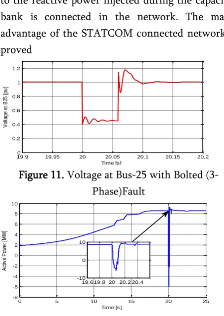
It is found that, the active and reactive power injected at B25 when STATCOM is connected to the system. It is evident that the reactive power support is increased in the second case as compared to the reactive power injected during the capacitor bank is connected in the network. The major advantage of the STATCOM connected network is proved
Figure 11. Voltage at Bus-25 with Bolted (3-Phase)Fault
Figure 12. Active Power Injected in the B25 during Fault
V.
REFERENCES
[1]. S. Heier, Grid Integration of Wind Energy
Conversion Systems, New York: Wiley, 1998.
[2]. M.T. Abolhassani, H.A. Toloyat, and P.
Enjeti, "Stator flux-oriented control of an integrated alternator/active filter for wind," Proceedings of the IEEE International Electric Machines and Drives Conference, Vol. 1, pp. 461–467, June 2003.
[3]. Eel-Hwan, S.-B. Oh, Y.-H. Kim, and C.-S.
Kim, "Power control of a doubly fed
transducers," Proceedings of the Power Electronics and Motion Control Conference, Vol. 2, pp. 951–955, August 2000.
[4]. H. Azaza and A. Masmoudi, "On the
dynamics and steady state performance of a vector controlled DFM drive systems," IEEE International Conference on Man and Cybernetics, Vol. 6, p. 6, October 2002. [5]. A. Tapia, G. Tapia, J.X. Ostolaza, and J.R.
Saenz, "Modeling and control of a wind turbine driven DFIG," IEEE Transactions on Energy Conversion, 18, 194–204, 2003. [6]. L. Jiao, B.-Teck Ooi, G. Joos, and F. Zhou,
"Doubly-fed induction generator (DFIG) as a hybrid of asynchronous and synchronous machines," Electric Power Systems Research, 76, 33–37, 2005.
[7]. B.H. Chowdhury and S. Chellapilla,
"Double-fed induction generator control for variable speed wind power generation," Electric Power Systems Research, 76, 786–800, 2006.
[8]. Y. Lei,A. Mullane, G. Lightbody, and R.
Yacamini, "Modeling of the wind turbine with a doubly fed induction generator for grid integration studies," IEEE Transactions on Energy Conversion, 21, 257–264, 2006. [9]. F. Wu, X.-P. Zhang, K. Godfrey, and P. Ju,
"Modeling and control of wind turbine with doubly fed induction generator," Power Systems Conference and Exposition, pp. 1404–1409, October–November 2006.
[10]. J.B. Ekanayake, L. Holdsworth, X. Wu, and N.
Jenkins, "Dynamic modeling of doubly fed induction generator wind turbines," IEEE Transactions on Power Systems, 18, 803–809, 2003.
[11]. W. Hofmann and A. Thieme, "Control of a
double-fed induction generator for
wind-19.9 19.95 20 20.05 20.1 20.15 20.2
0 0.2 0.4 0.6 0.8 1 1.2
Time [s]
V
ol
ta
g
e
at
B
25
[
pu
]
0 5 10 15 20 25
-8 -6 -4 -2 0 2 4 6 8 10
Time [s]
A
ct
iv
e
P
ow
er
[
M
W
]
19.619.8 20 20.2 20.4 -10