Engineering Studies of The Control Structure of
Electro-Hydraulic Pumps And Variable Axial
Pistons
L. Vaida, D. Banyai, P. A. O Adegbuyi, J. O. Uhomoibhi
Abstract :- Pumps are often used in both industrial applications and mobile hydraulic machinery. In variable displacement pumps, the flow rate is dictated by the system requirements. The electro-hydraulic pump is a new integrated product, which comprise the combination of a pump and motor as a unit replacing the traditional connection with a shaft coupling. The pump is actuated without a rotating shaft utilizing a piston pump embedded in the motor. This brings with it some added advantages such as easy installation, reduction of noise in the system and decrease in power loss. In operation, the piston pump body is placed in the motor rotor, the air gap between the rotor and motor stator is filled with hydraulic oil, the rotor is directly rotated in the hydraulic oil and the control of the pressure and flow is achieved by means of the mechanical adjustment at the pressure valve. Electro-hydraulic systems with volumetric control offer a lot of advantages for pumping, due to the use of axial pistons with variable displacements possibilities. Several researchers have tried to describe the performance structure of these pumps in relation to efficiency; energy loss etc. without needed success. Previous studies have shown that using single loop suppress the steady state vibration, causes relatively good valve performance and reduces the impact on the control piston at the ends of a system’s strokes. The use of single feedback control loop reduces the pump production cost whilst maintaining reasonable performance useful for many different and acceptable commercial applications. In our research work we carried out some engineering studies of the control structures of these systems by investigating the characteristics, the convenience and dependence on control scheme and power operation. This paper focuses particularly on the automation of the control systems of these pumps. A system that enhanced the control of flow, pressure and hydraulic power without modifying the structure of the pump was designed, fabricated, tested and is hereby presented. We report on the relationship and dependence of control scheme on power operation and conclude that the use of either single or double feedback loop scheme is largely dependent of the demand and need to protect the pump drive motor.
Keywords:-Electro-hydraulic, variable-displacement, pumps, pressure, flow, power, control.
1. Introduction
Electro-hydraulic pumps are a new integral product in which the pump and the motor are combined in one unit replacing the traditional connection with a shaft coupling. The embedding of a piston pump in the motor rotor has the capability to actuate the pump without a rotating shaft coupling. In recent proposals for an active elecro-hydraulic system analysis and in much of the work done by leading industries such as Eaton, Dynex and Daikin [1] there still seem to be lacking a performance analysis. In the testing several techniques are used. Some of these include water pressure test, pressure proof test, endurance test, functional test, worn-in test [2, 3]. Essential trends, manifested in today’s manufacturing of hydraulic machines are those of flexibility and automation, meaning increase in their level of intelligence and adaptation to possible disturbances and excitations. Introducing the concept of flexible system that involves the creation of auto-tuning systems capable of adapting to changes in manufacturing technology, through minimum intervention, and also adaptation in relation of any disturbing factor, embedded in a fully automated assembly in which human intervention is minimized or not required [4-6].
The elimination in general almost complete of the human operator has led to increased productivity by drastically reducing the time needed for big decisions to be taken in the handling of semi-manufactured products, where necessary in the case of tool wear, diagnosis and maintenance service. Hydraulic systems act as a subsystem of machines that must satisfy the requirements similar to that of mechatronic systems. This would not be achievable without the use of computer resources and the concept of mechatronics that have led to increased reliability of the component systems by increasing the precision of execution of the constituent components, dynamics, ensuring proportionality between command signals and ordered parameters. An important aspect was to transfer the logic of the control from medium and large energy level in a very low energy level, characteristic to electronic and computerized systems. Separation of energy flows brought the advantage of simplifying construction and the mechanical elements of forces, led to the modularisation of systems and implicitly to simplify the various actuation concepts. Introduction of automatic control systems and the sensors associated with computerized processing and command, led to the growth of intelligence of these systems, that become capable of self-adaptation in terms of external factors change.
Although starting from the ’80s, companies with a tradition in manufacturing pumps and motors with axial piston and variable displacement, produced these machineries for high automation systems (Rexroth, Bosch, Vickers, Parker.) the existing data in the literature on constructive solutions are few [7]. The great hydraulic machines manufacturers opt for mechanical-hydraulic control structures that allow their use in circuits regulating pressure, flow and power independently of one another, each requiring a different type of constructive control structure. High power, drives namely hydraulic systems, pursuing a high degree of automation, minimum power consumption, adaptability to a ____________________
• Faculty Of Mechanical Engineering, Technical University of Cluj-Napoca,Romania,
email: [email protected] & [email protected]
• Faculty of Engineering, Lagos State University OJO, Lagos, Nigeria, email: [email protected] (author for correspondence)
large range of industrial applications and perturbations becoming flexible systems. Variable displacement pumps allow easy control of system parameters (pressure, flow, power, or combinations between them). Their technical characteristics make them become the best option for most applications from machine tools to mobile devices.
Figure 1 Variable displacement pumps
2. Electro-hydraulic pumps – Features, Analysis
and Control Structures
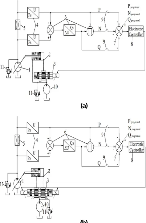
In electro-hydraulic compound pump the control of the pressure and flow is achieved through the setting of the output pressure at a mechanical pressure valve, which then produces an output flow that depends on the angle of tilting disk, generated at the control valve. We will add to some components in the compound pump, including the following: pressure sensor, flow sensor, inverter, and single chip microcomputer. The framework with an electrical signal way is given for controlling output pressure and flow of the electro-hydraulic compound pump. The electrical signal is provided to the proportional solenoid. The output pressure and flow of the compound pump is controlled based on the electrical signal to the proportional solenoid. The use of this type of electronically controlled variable pumps features many advantages such as reduction of energy requirements, high control accuracy, sensing and evaluation of several operating parameters, fast response times, fail safe behavior, system long service life and interface for diagnostic trouble shooting. The purpose of the present work was to seek the optimization and the adjustment of the strstructure of hydraulic parameters, their control in the system to which they belong and testing the assembly pump-adjustment system. Below is presented a schematic diagram for automatic control system proposed for implementation in a research program, in two versions. The difference between the two diagrams lies in the linear hydraulic motor control. In the first case the motor is commanded with two variable hydraulic resistors for motor control, and in the second case we have four variable hydraulic resistor that control the hydraulic linear motor.
(a)
(b)
Figure 2 Electro-hydraulic control system for variable displacement machines
3. Experimental
To achieve these objectivest a stand was designed and fabricated, capable of testing the performances of adjustable pumps with the possibility of controlling pressure, flow-rate, power or combination of these. A picture and a schematic representation of the experimental plant is shown in Figure 3. The main sub-assemblies of the plant include: pump with electro-hydraulic adjustment system (1), hydraulic energy source for control supply (2), specific sensor (3) Electric supply and control system for: proportional distributor, sensors and the load simulation distributor (4), acquisition and control hardware system (5), command and control interface (6) and load simulator (7). The test pump is primed at constant speed of 1450 rev/min, with a three-phase asynchronous electric motor of 15 kW rated power. In order to increase the universality of the stand a hydraulic group with pump for flow control was incorporated . Flow requirements (betw) 2.5 - 3 l/min. Hydraulic group for the command supply was made up of the following: gear pump (PRD 1-217 - Plopeni UM), providing a flow of 3.75 l/min at a pressure set in the range 20-100 bar, filter; pressure limiting valve and pressure gauge. The supply of the control circuits in this way is advantageous in terms of energy balance, because the control circuits of the pump worked in a resistive manner.
Figure 3 Photo and schematic of stand overview
To measure the load, a pressure transducer specific to fluid power systems, high working pressure (400 bar) was used The supply signal is analog, voltage between 0-10V . For flow measurement two identical pressure sensors, mounted in a block, one before and one after the diaphragm were used (see Figure 4).
Figure 4 Block housing for pressure sensors used in flow measurement
In order to have an apropriate value between the measured flow and the real value for the flow, a sensor calibration and filtering of signals with low-pass filter of second order was required. The difference between the signals, the square root of the pressure variation on the diaphragm and the multipication with the diaphragm constant were made using the automation and control software developed with Matlab Simulink. The systems for processing and conditioning the signals from transducers were realized utilising software processing because the facilities and simplicity of implementation that DSpace system providesre better as they are not analog processing which requires a large number of electronic components. The signal that represents the power given by the pump was obtained by multiplying the signal from pressure sensor located downstream of the diaphragm and the signal representing the flow. The operation was performed also using the automation and control software.
To create a workload two adjustable throttle and a way valve mounted on a block were used (Figure 5).
Figure 5. Load simulator
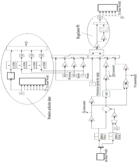
This simulating solution of the load is justified given that in an automatic adjustment circuit, the output size (adjusted) is influenced primarily by the size of the input (driving) and other interferences. The most common interferences observed in hydraulic pumps and motors are caused by the pressure load. The software package ControlDesk (associated to dSpace hardware system) contain libraries that makes it possible to access the physical modules directly from the programming environment Matlab - Simulink. Applications for acquisition and signal generation, as well as monitoring and control, were done through Simulink graphical programming. By compiling these files applications generated for real-time processor,which are transferred to it by a optical fiber bus for high-speed real-time applications are running on CPU integrated in dSpace, while graphical, control were monitoring interfaces running on the computer attached to dSpace system. Figure 6 represents the software console for command and control of the adjustable pumps created with Simulink. The signals from the two pressure sensors are filtered (signal sensor 2 is corrected by sensor 1), following which, the flow and the power is calculated. The value of the system pressure is measured by sensor 1 after filtration.. Signals corresponding to desired value for pressure, flow and power, are compared with the setpoint of these parameters in a differential block (constant blocks marked with: pressure, flow, power). The signal resulting from the operation of difference is fed into a PI controller, the output signal is available at the analog exit port of dSpace system. The selection of the adjustment type, the command value and the real value of the adjusted hydraulic parameter are made using two programmable switches. Data acquisition commences when pressure, flow command is actuated or when there is significant interference.
Figure 6. The command and control graphic interface
4.Results and Discussions
The experimental research on the dynamic behavior of the electro-hydraulic control system presented, were based on the response to step signal command. The controller used in the experiments was carried out using a software suite. After tunning the controller the following constants were determined that offers good dynamic behavior for the system regardless of the chosen control type:
Kp = 0,35;
1/Ti = 12.
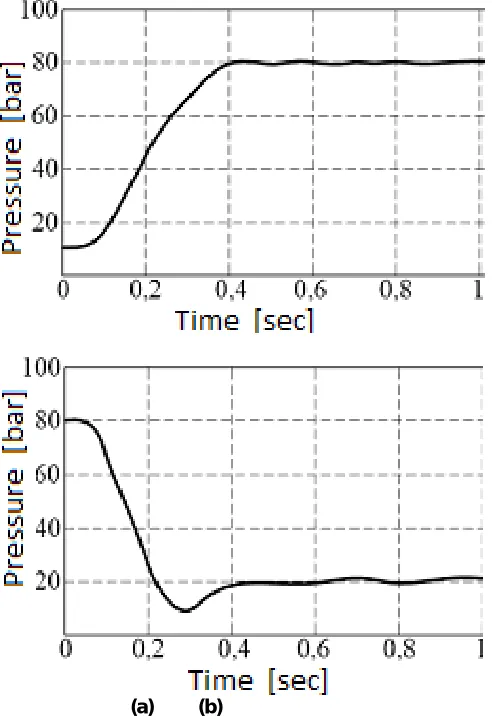
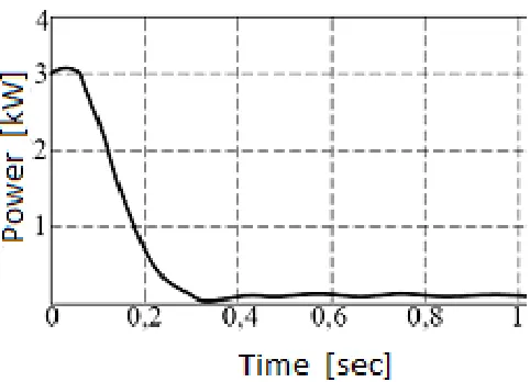
An important objective of the research was to study the behavior of the PID controller to various control structures. The dynamic behavior of the control structure was investigated by recording the signal step response which gives the command for pressure, flow and power. Figures 8 to 10 represents the graphical form of the data corresponding to a set of tests carried out on the stand for the three major types of control.
(a) (b)
Fig. 8 System response to a pressure command of 10 bar and 80 bar respectively
Fig. 10 System response to a power command of 0.1 kW and 3kW respectively
The control of flow and performance of electro-hydraulic pumps to include pressure and power of volumetric pumps and motors is necessary. The speed has to be attended with minimumenergy loss, the mechanical power of the electric motor should be kept constant and the flow delivered by the pump decreased to achieve an imposed value of pressure and avoid a situation of having fluid being thrown to the tank [8, 9]. By availaling of the reversibility between the pump and motors, both the flow and speed of teh system coudl be conrolled. Existing technical solution derives from main feature, the mechanism of tilting the piston block following an imposed mechanical law and varying the angle. In ordr to control the hydraulic flow of the pump with axial piston Analysis of the results as shown in the results suggests very short periods of time for pressure supplier of hydraulic pumps [10, 11]. These pressure values are the main cause of continuous variation of the resistant forcerequired for sloping the axial piston block of the pump.
5. Conclusion
The design, fabrication and testing of systems such as the one reported in this paper enable the achievement of reduced complexity of control circuit construction. Cost is reduced as it does not involve the use of special equipment at high cost. The mechanical structure of the pump is not affected when another hydraulic parameter needs to be controlled and the control scheme is integrated with piloting and tracking mechanism into a compact system with small sizes [12, 13]. The system was found to be well damped, stationary error was well below 2%, the response time was less that 0.5 seconds and after tunning, the controller was found to be able to use the same constants for all three types of control investigated. The control system proves satisfactory behavioral skills for any adjustment structure, in terms of practical requirements and the current system demontrated that the adjustment of the three important hydraulic parameters can be achieved, unlike conventional techniques, with the same pump, the same controller and only two pressure sensors by a simple electrical switching. axial piston machines with variable displacement and
complex equipments by interfacing with a PLC or process computer. The continuous control of hydraulic parameters using electric input is an important characteristics. This control process influences the values of eccentricity, in the case of pumps with radial pistons, or the slope angle of the block with axial pistons as components of such a hydraulic pump. We conclude that this type of system could be used directly for other possitioning systems of high accuracy. It is a solution system for conrolling and achieving efficiency wih hydrapumps and motors.
References
[1] Yannis, K., Anthony, T., and Demosthenes, T. (2006). Multi-Parametric Optimization of a Pulse Width/Phase Modulated Controller a High Frequency Active Electro-Hydraulic Pump System. Proceedings of the 45th IEEE Conference on Decision & Control, San Diego, CA, USA, pp. 5335-5340.
[2] Hwang, M.T. (2006). An Electro-hydraulic Compound Pump Test Report, Technical Report, CSIST-0443-T303(95). Subsystem Group, Aeronautical Research Lab., Taiwan, R.O.C.
[3] Wu, Y.C. (2006). An Electro-hydraulic Compound Pump Test Procedure, Tech. Rep., CSIST-0443-T302(95), Aeronautical Research Lab., Chung-Shan Institute of Science and Technology , Taiwan, R.O.C.
[4] Banyai D., Vaida L., Electro-hydraulic control system for variable displacement machines, 12th International Conference „Automation in Production Planning and Manufacturing“, p. 50-58, Zilina, Slovacia, 2011.
[5] Banyai D., New methods in synthesis of hydraulic machines with variable displacement and electro-hydraulic adjustment, PhD Thesis, Technical University of Cluj-Napoca, Romania, 2011.
[6] He Q.H., Hao P., Zhang D, Zhang H.T., Modeling and Control of Hydraulic Excavator’s Arm, Journal of Central South University of Technology, Vol. 13, Nr. 4, p. 422-427, 2006.
[7] Năşcuţiu L., Banyai D., Marcu I.L, Control system for hydraulic transmissions specific to wind machines, DTMM 2010, Buletinul Institutului Politehnic din Iai, ISSN 1244–7863, Iai, Romania, 2010.
[8] N. Alexandrescu, ‘Electro-hydraulics Units for incremental positioning’(in roumanian), In Hidraulica, Buletin Informativ, Nr. 3, 1997.
[10] Năşcuţiu L., Banyai D., Opruţa D., Measurement of hydraulic parameters, DTMM 2010, Buletinul Institutului Politehnic din Iai, ISSN 1244–7863, Iai, Romania, 2010.
[11] Năşcuţiu L., Banyai D., Marcu I.L, Hardware in the loop concept applied to control the voice coil actuator used in hydraulic servo-valves, Annals of DAAAM for 2009 & Proceedings of 20th DAAAM International Symposium, No.1, Vol.20, pg. 1247, ISSN: 1726-9679, Viena, Austria, 2009.
[12] Vaida L., Proportional control for adjustable pumps, PhD Thesis, Technical University of Cluj-Napoca, Romania, 1999.