255
Performance Evaluation Of IEEE 802.11e MAC
Layer Using Cell Processor
A. Poonguzhali
Abstract: IEEE802.11e is a new 802.11 Wireless LAN (WLAN) standard, which supports applications with Quality of Service (QoS). It is widely considered to play a major role in multimedia wireless home networks. The Cell Broadband Engine is a new multicore microprocessor architecture for high performance computer applications. In this project, we are trying to provide a simple simulator framework for IEEE 802.11e as well as its implementation in CELL processor. The simulator will run in a uni-processor (x86) which will provide the performance evaluation of IEEE 802.11e MAC. The simulator in CELL processor will perform the same operation as the simulator developed for uni-processor, with additional speed up. The multicore processing capability of the CELL processor, will provide fast and reliable simulation results as it is done in a uni-processor machine.
————————————————————
1. Introduction
In ad-hoc wireless networks, each node can communicate directly with each other only if they can reach each other physically, i.e., if they are within each other's radio range or if other nodes can forward the message. In ad-hoc networks, the complexity of each node is higher because every node has to implement medium access mechanisms, mechanisms to handle hidden or exposed terminal problems, and perhaps priority mechanisms, to provide a certain quality of service. This type of wireless network exhibits the greatest possible flexibility as it is, for example needed for unexpected meetings, quick replacements of infrastructure or communication scenarios far away from any infrastructure. The architecture of wireless LAN is divided into Physical (PHY) and Medium Access Control (MAC) as per IEEE802.11e. A Co-ordination function can determines when a particular node can access the medium with in a BSS (Basic Service Set) to transmit and receive a Protocol Data Unit (PDU). IEEE802.11e is an enhanced version of IEEE802.11 MAC in order to support quality of service (QoS). In IEEE802.11e, the AP and STA provides QoS service are referred to as QAP (QoS Access Point) and QSTA (QoS Station) respectively. IEEE802.11e defines a new coordination function called Hybrid Coordination Function (HCF) to provide QoS support. HCF is a centralized coordination function that combines the aspects of DCF and PCF. It provides both distributed and centrally controlled channel access mechanisms similar to DCF and PCF [1]. Discrete event simulation of Telecommunications systems is generally a computation intensive task. A single run of a wireless network model with thousands of mobile nodes may easily take several days and even weeks to obtain statistically trustworthy results even on today’s computers, and many simulation studies require several simulation runs.
Independent replicated simulation runs have been proposed to reduce the time needed for a simulation study, but this approach is often not possible (for example, one simulation run may depend on the results of earlier runs as input) or not practical. Parallel discrete event simulation (PDES) offers an attractive alternative. By distributing the simulation over several processors, it is possible to achieve a speedup compared to sequential (one-processor) simulation [2] [3]. Parallel network simulators are already exists, but for sequential processors. For examples GloMoSim developed by University of California [2], OMNET++ by Andras Varga [4] are some examples of parallel discrete event simulation for wireless networks.
2. Overview of cell processor
Initial discussion on the collaborative effort to develop Cell began with support from CEOs from the Sony and IBM companies: Sony as a content provider and IBM as a
leading-edge technology and server company.
Collaboration was initiated among SCEI (Sony Computer Entertainment Incorporated), IBM, for microprocessor development, and Toshiba, as a development and volume manufacturing technology partner. This led to high-level architectural discussions among the three companies during the summer of 2000. The Cell objectives were to achieve 100 times the PlayStation2 performance and lead the way for the future. The most high-profile commercial application of the Cell processor is the Playstation 3 games console, which was released on the November 2006. IBM is already producing Linux-based servers running on Cell, and Toshiba has demonstrated Cell’s ability to decode many MPEG-2 streams simultaneously, presumably as a precursor to Cell-powered televisions and multimedia centers. Apart from the above game console applications, Cell processors are used for building servers. Cell blade servers are already available and can be used for high end applications like weather forecasting, ray tracing, image processing etc.
2.1. Architecture
A single Cell processor chip is multiprocessor by design. It has of nine processors - one main processor called the PowerPC Processor Element (PPE) and eight coprocessors called Synergistic Processor Elements (SPEs) [5]. The PPE and eight SPEs are connected via Element Interconnect Bus (EIB), a high-bandwidth memory-coherent bus which is used by the processors to communicate with each other, external memory and I/O devices (see Figure 1). ________________________
Poonguzhali: Assistant Professor, Department of
Electronics and Communication, Shirdi Sai
Engineering College, Anekal, Bangalore.
Compatible devices such as another CBE can also be attached through the CBE interface. A single Cell blade server consists of two Cell processors interconnected together to give a high performance.
Figure -1 Cell Broadband Engine Architecture
2.2. The PowerPC Processing Element
A PowerPC Processing Element consists of a dual-threaded SIMD 64-bit RISC PowerPC processor (the PowerPC Processor Unit or PPU). Apart from the PPE, it also has a storage subsystem that governs memory requests from the PPE and external requests to the PPE from other processors. The PPE is a general-purpose processor optimized for running control intensive software such as an operating system, coordinating all processes running on Cell. The PPE is not intended to perform all primary processing for the system, but rather to act as a controller for the other eight SPEs, which handle most of the computational workload.
2.3. The Synergistic Processing Element
The Synergistic Processing Elements are specialized 128-bit SIMD RISC processor (the Synergistic Processor Unit or SPU) and a Memory Flow Controller (MFC). The SPUs are designed to run compute-intensive code at the expense of branch-prediction and out-of-order-processing hardware. The SPU cannot access the main memory directly instead, each SPU contains both 256KB of Local Store SRAM and a 128-entry register file. The SPU uses this Local Store to store both data and instructions for the SPU. The function of Memory Flow Controller is for transferring data in and out of the Local Store of its corresponding SPU. It does this through a local Direct Memory Access (DMA) controller allowing the SPU, PPU, or another SPU to request a data transfer to or from main memory. In this way the SPE’s DMA controller can autonomously transfer data to the Local Store while the SPU is processing other data. To increase the efficiency still further double buffering can be used and hiding the memory latency behind computation time. Each DMA transfer can be up to 16,384 bytes (16KB) in size, and an SPU can have up to 16 outstanding DMA requests queued (or 2,048 if using a special DMA-list construct, ideally suited for scatter-gather operations). The theoretical peak bandwidth for the EIB is 204.8 GB/s [6].
2.4. Programming Cell
For software development of cell processor IBM is releasing, Cell SDK from the beginning of November 2005. The Cell SDK includes all the binaries for developing the application for Cell processor. It has GNU GCC as well as IBM’s XLC compiler. Currently Cell SDK supports C and C++ languages. The main feature of the Cell SDK is the Full System Simulator (in IBM internally called as “mambo”). The FSS allows the user to develop the application for cell processor without the actual hardware. Our paper uses the Cell SDK 2.0 for the code generation.
3. Modeling and simulation of EDCA
The EDCA provides differentiated, distributed access to the medium using different priorities for different types of data traffic. The EDCA components and operation is described as follows.
3.1. Access Categories (ACs)
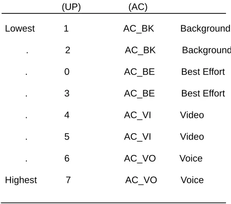
EDCA defines four Access Categories (ACs) for different types of data traffic, and service differentiation for each AC, a different set of parameters is used to contend for the medium. These parameters are referred to as EDCA parameters. Frames from different types of data traffic are mapped into different ACs depending on the QoS requirements of the traffic/application the frames belong to. The four Access Categories are named AC_BK, AC_BE, AC_VI and AC_VO, for Background, Best Effort, Video and Voice data traffic, respectively, where AC_BK has the lowest and AC_VO has the highest priority. Each frame from the higher layer arrives at the MAC layer along with a priority value. This priority value is referred to as User Priority (UP) and assigned according to the type of application/traffic the frame belongs to. There are eight different priority values ranging from 0 to 7.
Priority User Priority Access Category Designation
(UP) (AC)
Lowest 1 AC_BK Background
. 2 AC_BK Background
. 0 AC_BE Best Effort
. 3 AC_BE Best Effort
. 4 AC_VI Video
. 5 AC_VI Video
. 6 AC_VO Voice
Highest 7 AC_VO Voice
Table -1 User Priority (UP) to Access Category (AC)
257
The draft standard does not specify how priority is assigned at the higher layers. Generally, it can be assigned by application generating the traffic, or by the user using the application. Another possibility would be to adaptively assign the priority at the Application layer, based on the traffic characteristics e.g., data rate, packet3 interval, packet size etc. At the MAC layer, a frame with a particular UP is further mapped to an AC. ACs are derived from the UPs as illustrated in Table 1.
3.2 EDCAF (Enhanced Distributed Channel Access Function)
Every station maintains four transmit queues one for each AC, and four independent EDCAFs (Enhanced Distributed Channel Access Function), one for each queue, as illustrated in Figure 2. EDCAF is an enhanced version of DCF, and contends for the medium
Figure-2 Four ACs, each with its own queue, AIFS, CW and
backoff timer.
on the same principles of CSMA/CA and backoff, but based on the parameters specific to the AC.
3.2.1 EDCA Parameters
An EDCAF contends for medium based on the following parameters associated to an AC:
• AIFS - The time period the medium is sensed idle before the transmission or backoff is started. • CWmin, CWmax - Size of Contention Window used
for backoff.
• TXOP Limit - The maximum duration of the transmission after the medium is acquired.
The values of EDCA parameters5 are different for different ACs. The higher priority ACs wait a small AIFS time period while the lower priority ACs have to wait a longer AIFS time before they can access the medium. The size of Contention Window varies such that the higher priority ACs choose backoff values from a smaller Contention Window
Figure 2.2: Prioritization based on AIFS.
AIFS (Arbitration Inter-Frame Space) - The minimum time
period for which the medium must be sensed idle before an EDCAF/station may start transmission or backoff is not the fixed value DIFS, as it is in DCF, but is a variable value, AIFS, that depends on the AC for which the EDCAF is contending for. AIFS is derived from the following equation:
AIFS = AIFSN x aSlotTime + aSIFSTime,
where aSlotTime is the slot time, aSIFSTime is the SIFS time period and AIFSN (Arbitration Inter-Frame Space Number) is used to determine the length of the AIFS. AIFSN specifies the number of time slots in addition to the SIFS time period the AIFS consists of. Different AIFSN values are used for different ACs such that the high priority
AC CWmin CWmax AIFSN TXOP Limit
FHSS DSSS
AC_BK CWmin CWmax 7 0 0
AC_BE CWmin CWmax 3 0 0
AC_VI (CWmin+1)/2-1 CWmin 2 6.016ms 3.008ms
AC_VO (CWmin+1)/4-1 (CW+1)/2-1 2 3.264ms 1.504ms
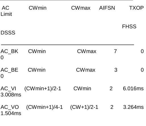
Table-2 Default EDCA parameter values.
The smaller AIFSN value for a higher priority AC explains that the corresponding EDCAF has to wait shorter time period before it can start transmission or counting down its backoff timer compared to the EDCAF for a low priority AC. In this way, the higher priority ACs are guaranteed greater share of the bandwidth. Moreover, smaller AIFS lengths ensure that the higher priority ACs will not suffer from long delays, which are vary critical for the delay-sensitive applications/traffics. The lower priority ACs may suffer from longer delays because of the larger AIFS durations they have to wait, but since these ACs are designed for delay-tolerant applications/traffics, certain amount of delays do not degrade their performance beyond an acceptable limit.
CWmin and CWmax - The minimum and maximum
Contention Window size limits are not fixed and that can be varied depending on the AC. The higher priority ACs have smaller CWmin and CWmax values compared to lower priority ACs. The default values of CWmin and CWmax parameters for each of the four ACs are presented in Table 2.
TXOP (Transmission Opportunity) - As described above,
TXOP is the time duration an EDCAF may transmit after winning access to the medium. TXOP is characterized by a maximum duration, called TXOP Limit. As an EDCAF gets the TXOP, it can then start transmitting frames such that the transmission duration does not exceed the TXOP Limit. The transmission duration covers the whole frame exchange sequence, including the intermediate SIFS periods and ACKs, and the RTS and CTS frames if RTS/CTS mechanism is used.
4. Event generation functions
259
ARRIVAL RE-ARRIVAL SUCCESSFUL
TXN
UN- SUCCESSFUL
TXN EVENT GENERATORS
EVENT SCHEDULER
ARRIVAL RE-ARRIVAL SUCCESSFUL
TXN
UN- SUCCESSFUL
TXN EVENT HANDLERS
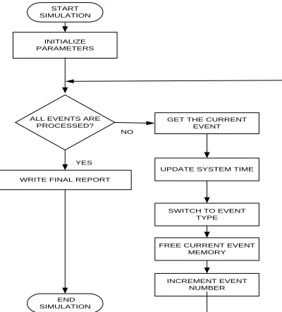
START SIMULATION
INITIALIZE PARAMETERS
ALL EVENTS ARE
PROCESSED? GET THE CURRENT EVENT
UPDATE SYSTEM TIME
SWITCH TO EVENT TYPE
FREE CURRENT EVENT MEMORY
INCREMENT EVENT NUMBER WRITE FINAL REPORT
END SIMULATION
YES NO
1. ARRIVAL – This Event specifies the instant when a packet is generated. The packets are generated using nodal arrival rate and poison distribution. An event list is maintained to arrival time of packets for each node.
2. RE-ARRIVAL – This is an event for the time when there is a collision and multiple nodes are competing for the channel.
3. SUCCESSFUL TXN – A node senses the wireless medium, for transmission. On successful detection of the free medium the packet is transmitted. An event named as SUCCESSFUL TRANSMISSION of packet is added in the event list.
4. UNSUCCESSFUL TXN – The probability of successful packet transmission is always low in wireless communication as compared to wired communication.
For realistic simulation, probability of error is included, for loss of packet. Whenever a packet is lost, the event is considered as UNSUCCESSFUL TRANSMISSION of packet. The number of nodes that we considered for the simulation is around 40 to 50. The Channel capacity is 2Mbps, propagation delay of 3.3 microseconds. The nodal arrival rate is considered to be 1. Numbers of bits per packets are 2048 bits. It is possible to vary the above parameters and run the simulation for different values of system parameters. Since we used the minimal EDCAF implementation, other less important parameters as said in [6] are ignored.
5. Implementation
This section discusses the implementation of the MAC simulation in the CELL processor. The full implementation can be divided into three major parts as below:
1. Generation of initial ARRIVAL events at PPE
2. Transfer of event list to SPE and MAC simulation.
3. Collection of results back by the PPE and combining the results.
5.1. Initial Event Generation
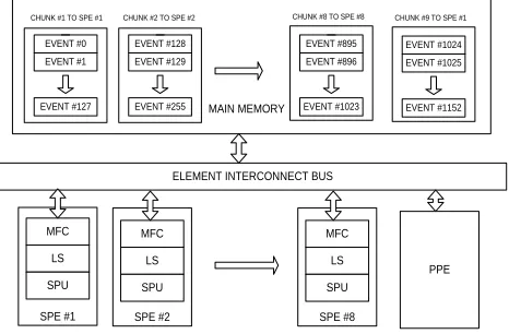
The initial simulation parameters such as simulation time, number of nodes, capacity of channel, DIFS interval, SIFS interval,AIFS interval, Node arrival rate and other parameters are initialized. The events are generated by the nodal arrival rate (lambda) and Poisson distribution. In our case we have developed 8192 events. To distribute the MAC simulation eight threads are created in the PPE. When the threads are created the control is switched to the eight SPEs. This is as shown in the figure 4. The event list is generated in the main memory and stored in the array. The total memory taken by the event list is 8192 events x 8 bytes (data type for event time is double) = 64KB.
Figure 3 – Discrete Event Simulation of IEEE 802.11e MAC
EDCA
If the wireless medium is found to be free, the packet is scheduled to be transmitted after specified time. Else the packet will re-arrive according to nodal arrival rate and poison distribution. Apart from the channel busy status, the probability of status is also considered for realistic simulation. The successfully transmitted packets, deferred packets and dropped packets are transferred back to the PPE. All the SPEs processes MAC simulation in similar way and send back the result to the PPE.
Figure 4 – Operation of Discrete Event Simulation
5.3 Calculation of Throughput
SPE #8 SPE #2
SPE #1 EVENT #0 EVENT #1
EVENT #127
EVENT #128 EVENT #129
EVENT #255
EVENT #895 EVENT #896
EVENT #1023
MFC
MAIN MEMORY
LS
SPU
MFC
LS
SPU
MFC
LS
SPU ELEMENT INTERCONNECT BUS
PPE CHUNK #1 TO SPE #1 CHUNK #2 TO SPE #2 CHUNK #8 TO SPE #8
EVENT #1024 EVENT #1025
EVENT #1152 CHUNK #9 TO SPE #1
Figure 5-a Simulation time Vs Number of Events for 1KB
DMA transfer rate
The operation of the MAC simulator is shown in the Figure 6. The events are divided into small chunks. Each chunk consists of 128 events and assigned to particular SPE. The events from the main memory are transferred to the local store of corresponding SPE via DMA. Once the SPE is done with the simulation, the results (i.e. number of packets transmitted, number of packets dropped etc.) are sent to the main memory. The PPE combine the results from the rest of the SPE and calculate the throughput of the system.
Figure 6. Implementation in Cell processor
6. Simulation Results
Initially a sequential version of code is developed for the above MAC simulator in x86 processor. The code for Cell processor is written in C language, using Full System Simulator, which comes with CELL SDK 2.0. The PPE code mainly concentrates on the generation of initial events and thread creation. The compute intensive task of MAC simulation is carried out by all SPUs. The simulation was carried out for 4096, 8192, 16384, 32768 and 65536 events. Figure 6 shows the time elapsed for the MAC simulation being carried out in 3.2 GHz Pentium Dual Core, PPU alone, 2 SPUs, 4 SPUs, 6 SPUs and 8 SPUs. It is evident that as the simulation is carried in more number of SPUs the simulation time decreases. Since in the x86 alone all the events has to be manipulated in the single processor. On the other hand, when the simulation is carried out in the 8 SPUs, the events are equally divided among the SPUs. This will eventually speed up the simulation process. The above simulation is carried, with a DMA transfer rate of 1KB. Similarly DMA transfer rate of 2KB was also simulated. The speed up provided by the Cell Broadband Engine is very impressive. A comparative graph which
shows the speed up provided by the Cell Broadband Engine, with simulation being carried out in 8 SPUs is shown in Figure 7. A typical calculation of the throughput for the 4096 events with a DMA transfer rate of 1KB, carried out in 4 SPUs is shown in the Figure 8.
Figure 7 – The Speed up of simulation time provided by
Cell Broadband Engine
Figure 8 Throughput Calculation
7. Conclusion and Future Work
The MAC simulation in this paper is shows the minimal functionality of the MAC layer. It is possible to enhance the user interaction through adding animation to represent the packet transmission, ACK transmission, ect.., as in the NS-2(Network Animator) . The 256KB local store of the SPE imposes much restriction on the programmer. Apart from the MAC simulation, a full fledged network simulator is also possible to design using Cell processor. Already a parallelized version of ns-2 is carried out by College of computing, Georgia Institute of Technology [7]. Similar approach can be used to construct a parallel network simulator in Cell processor.
References
[1]. Jahanzeb Farooq, Bilal Rauf, “An Overview of Wireless LAN Standards IEEE 802.11 and IEEE 802.11e”.
[2]. Rajive Barodia, Mario Garla, “A Modular and Scalabale simulation Tool for Large Wireless Networks”, Lecture Notes in Computer Science, 1988
[3]. Sandeep Bhatt, Richard Fujimotto, Kalyan Permulla, “Parallel Simulation Techniques for Large Scale
Networks”, Bellcore, IEEE Communications
261
[4]. Andras Varge et.al,, “Parallel Simulation Made Easy With OMNET++”, European Simulation Symposium (ESS2003), Oct. 2003, Delft, The Netherlands
[5]. Cell Programming Handbook,
http://www-306.ibm.com/chips/techlib/techlib.nsf/products/Cell_B roadband_Engine
[6]. Peter Hofstee, “Introduction to the Cell Broadband Engine”. Technical report, IBM Corp., 2005