Abstract—Because of the load capacity design method cannot guarantee the structure to achieve the prospective plastic deformation or ductility requirement, so the displacement of pier should be calculated in the seismic design. This paper focuses on the ductile deformation and allowable displacement of reinforced concrete double-column piers under earthquake action. Based on the nonlinear analysis software ABAQUS, the seismic response and failure state of reinforced concrete double-column piers under transverse earthquake are studied through incremental dynamic analysis (IDA) method. According to the relationship between material constitutive and limit state, the displacements of piers are obtained in three different (the slightly damage limit state, controlled damage limit state and controlled collapse limit state). Besides the pier height and tie beam are also consider in the analysis. The relationship between the displacement angle and the strain of double-column piers under the transverse earthquake action is analyzed and a simplified formula of admissible displacement of pier is proposed. Through verification, this simplified formula is simple and accurate, and can be used in the preliminary design.
Index Terms—Double-column piers, admissible displacement
of pier, performance state, concrete damaged plastic model.
I.
I
NTRODUCTIONA large number of bridges damages after earthquake [1]-[3]
show that: Inadequate strength of bridge does not necessarily
lead to collapse, even serious damage. As long as the initial
strength of bridge meets the basic requirement, the increase of
inelastic deformation will not induce excessive decrease in
strength, and bridge will still meet service requirement with a
small amount of repair costs. However, if the inelastic
deformation cause a sharp strength decrease, the severe
failure or even collapse of bridges are usually observed.
Therefore, the control of pier displacement through ductility
design is the key to avoid pier collapse.
At present, the studies on the deformation calculation of
reinforced concrete column mainly focus on the deformation
bent capacity [4]-[7] and axial load capacity [8] in yield and
ultimate state, residual displacement [9] and the relationship
between ductility deformation bent capacity and restrain
stirrup [10], [11]. But few studies had been done on the
deformation calculation of different damage states involved in
the whole failure process. To complete and accurately define
Manuscript received January 22, 2017; revised April 1, 2017. This work was supported in part by the National Natural Science Foundation of China (Grant No.51178220 and 51108234), the Transportation Science and Technology project (2013Y12), and the Science and technology support program (BE2014716), Jiangsu, China.
The authors are with Nanjing Tech University, Nanjing, China (e-mail: [email protected], [email protected], [email protected], [email protected]).
the performance level of the component, it is necessary to
study the whole failure process.
In the Guidelines for Seismic Design of Highway Bridges
[12] (abbreviated as Guidelines) of China, the allowable top
displacement of single-pier less than 30m is given under the
horizontal and vertical seismic actions, but for double-
column piers and bent piers under seismic action are not
clearly given. The present researches are mainly for the
preliminary design of top displacement of double-column
piers, which is not applicable for the double-column piers
with tie beam for the different position of plastic hinge.
In this paper, the ductility deformation and admissible
displacement of reinforced concrete double-column piers
under earthquake are studied. The limit displacement of pier
is determined. Through the comparative analysis of various
factors, a reasonable and simple calculation formula of
permissible displacement of double-column piers is obtained,
which is conducive to the improvement of bridge seismic
design and code.
II.
D
EFORMATIONB
ENTC
APACITY OFR
EINFORCEDC
ONCRETEP
IERSA.
Guidelines for Seismic Design of Highway Bridges
Guidelines require that the deformation of B-type and
C-type bridge piers need to be checked, and a definite calmn
pier is obtained:
u P y
L
H
H
)
2
(
3
1
2u
(1)
θ
uis the maximum admissible angle in the plastic hinge
region:
K
L
p u yu
(
)
/
(2)
where,
K
is the ductile safety factor, taking as 2.0;
ϕ
yand
ϕ
uis yield curvature and limit curvature of the cross-section
respectively.
The
longitudinal
admissible
displacement
of
double-column piers and bent piers are the same as that of the
single pier. The transverse admissible displacements of piers
are required to be nonlinearly analyzed. When any plastic
hinge of pier reaches its maximum admissible angle, the
horizontal displacement at the bent cap is the admissible
displacement.
B.
Caltrans Seismic Design Criteria
A more detailed provision of pier displacement is
Study on Admissible Displacement Calculation Method
of Double-Column Piers
stipulated in Caltrans Seismic Design Criteria (abbreviated as
Caltrans) [13], and the double-column piers are divided into
three forms: rigid bent cap, flexible bent cap, flexible bent cap
with flexible foundation. The specific deformation situations
are in Fig. 1.
(a) Rigid bent cap
(b) Flexible bent cap
(c) Flexible bent cap with flexible foundation Fig. 1. Transverse displacement and plastic hinge of
double-column piers.
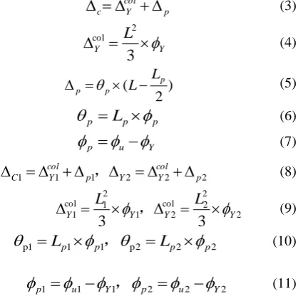
The displacement capacity,
∆
cof any column may be
idealized as one or two cantilever segments presented in
Equations (3-7) and (8-11), respectively. See Fig. 2 and Fig. 3
for details.
p col Y
c
(3)
Y Y
L
3
2col
(4)
)
2
(
pp p
L
L
(5)
p p
p
L
(6)
Y u
p
(7)
2 2 2 1 1
1 p
col Y Y p col Y
C
,
(8)
2 2 2 col
2 1 2 1 col
1
3
3
Y Y YY
L
L
,
(9)
2 2 2 p 1 1 1
p
L
p
p
L
p
p
,
(10)
2 2 2 1 1
1 u Y p u Y
p
,
(11)
where:
L
is distance from the point of maximum moment to
the point of contra-flexure;
L
pis equivalent plastic hinge
length;
Δ
cis idealized plastic displacement capacity due to
rotation of the plastic hinge;
Δ
pis idealized yield
displacement of the column at the formation of the plastic
hinge;
Δ
pcol
is idealized yield curvature;
ϕ
Yis idealized plastic
curvature capacity (assumed constant over
L
p);
ϕ
pis curvature
capacity at the failure limit state;
θ
pis Plastic rotation
capacity.
Fig. 2. Displacement capacity – cantilever column with fixed base
Fig. 3. Displacement capacity – framed column, assumed as fixed-fixed.
III.
N
UMERICALA
NALYSISM
ODELIn this paper, ABAQUS is used to analyze the performance
of double-column piers. The Concrete Damaged Plasticity
Model (CDP model) is adopted as the constitutive model of
concrete. The 3D solid linear reduction unit C3D8R and 3D
beam element T3D2 are used to simulated concrete and rebar.
The applied seismic wave is obtained by converting the
response spectrum from Guidelines.
Nonlinear station analysis, nonlinear dynamic analysis and
IDA are often used to analyze the nonlinear seismic response
characteristics of structure. IDA method can reflect the
seismic performance under different earthquake intensity, and
can make a more comprehensive and realistic evaluation of
the seismic bent capacity of structure. So IDA method is
adopted in this paper. The model parameters in this paper are
based on the parameters of a typical bridge. The basic
parameters of model are shown in Table I.
IV.
F
ORMULAS
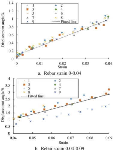
IMULATIONThe displacement angle - rebar strain curve of typical
double-column piers is shown in Fig. 4.
0 0.5 1 1.5 2 2.5 3 3.5 4
0 0.02 0.04 0.06 0.08 0.1
Displ
ac
ement
ang
le/%
Strain 1 2 3 4 5 6 7 8 9 10
Fig. 4. Displacement angle - rebar strain curve of typical double-column piers.
0 0.2 0.4 0.6 0.8 1 1.2 1.4
0 0.01 0.02 0.03 0.04
Displ
ac
ement
ang
le/%
Strain
1 2
3 4
5 6
7 8
9 Fitted line
a. Rebar strain 0-0.04
0 0.5 1 1.5 2 2.5 3 3.5 4
0.04 0.05 0.06 0.07 0.08 0.09
D
isplac
eme
nt
ang
le
/%
Strain
1 2
3 4
5 7
8 9
Fitted line
b. Rebar strain 0.04-0.09
Fig. 5. Displacement angle - rebar strain curve.
From Fig. 5, it can be seen that the relation between
displacement angle and strain is linear, so it is assumed that
the relationship formula is:
S
k
ABC
(
)
(12)
First taking
k
1=24.63 and
k
2=45.89, then based on the 10 m
double-column piers without tie beam, the coefficients
A
,
B
and
C
are determined by the relationship between
displacement angle and compression ratio, pier height, stirrup
ratio.
A
is defined as the axial compression ratio coefficient.
According to the previous research, it was found that the
displacement angle of double-column piers with the
compression ratio of 0.1, 0.2 and 0.3 is decreased by 20%.
Thus,
A
can be expressed in the form as
0.1 ) .1 0 (.8
0
A
, which
is the compression ratio.
B
is defined as the pier height coefficient. According to the
previous research, it was found that the displacement angles
of double-column piers with pier height of 5m, 10m and 20m
are almost the same in each performance state, while the
displacement angles of 30m double-column piers are 40%
smaller than that of 20m. Therefore,
B
can be expressed in the
form as
10 )20 (
.6
0
LB
, where
L
is the pier height,
L
20
m
.
C
is defined as is the stirrup ratio. As the stirrup ratio
affects core concrete compressive strain, and the compressive
strain of the double-pier concrete is less than control the
compressive strain -0.004 under transverse earthquake, so
C
is equal to 1.
Finally, after adjusting the values of
k
1and
k
2, the
displacement angle formula of double-column piers under the
transverse earthquake is obtained:
S
28
.6
,
=0~0.04
S
(13)
( 0.1) 20
( )
0.1 10
38 (0.8
) (0.6
)
L
S
,
S=0.04~0.09
(14)
where:
ε
sis the rebar strain;
ε
s=0.015 means slightly damage;
ε
s=0.06 means controlled damage;
ε
s=0.09 means controlled
collapse. Table II shows the displacements of each model.
TABLE I: PARAMETERS OF MODELNo Tie beam number
Pier Height/m
Section Diameter/m
Rebar
Diameter/m Compression ratio
Stirrups ratio/%
Longitudinal rebar ratio/%
1 1 10 1.3 28 0.1 0.40 0.6
2 0 10 1.3 28 0.1 0.40 0.6
3 0 5 1.2 28 0.1 0.40 0.6
4 2 20 1.4 28 0.1 0.40 0.6
5 3 25 1.5 28 0.1 0.40 0.6
6 3 30 1.6 28 0.1 0.40 0.6
7 0 10 1.3 28 0.1 0.60 0.6
8 0 10 1.3 28 0.1 0.80 0.6
9 0 10 1.3 28 0.2 0.40 0.6
10 0 10 1.3 28 0.3 0.40 0.6
TABLE II: THE TOP DISPLACEMENTS OF PIERS OF EACH MODEL IN EACH PERFORMANCE STATUS
N No
Performance status Displacement angle formula Slightly damage Controlled damage Controlled collapse
0≤
ε
s≤0.04 0.04≤ε
s≤0.09D /m DA /% D/m DA/% D /m DA/%
1 0.044 0.444 0.181 1.809 0.304 3.040 20.15
ε
s +0.115 41.05ε
s -0.6382 0.053 0.5 0.208 2.1 0.35 3.5 24.63
ε
4 0.105 0.527 0.365 1.825 0.641 3.204 23.41
ε
s +0.130 38.45ε
s -0.437 5 0.123 0.49 0.342 1.37 0.526 2.10 24.77ε
s -0.1 19.72ε
s +0.24 6 0.079 0.265 0.341 1.136 0.608 2.027 14.75ε
s +0.051 27.78ε
s -0.507 7 0.046 0.462 0.169 1.693 0.287 2.866 22.44ε
s +0.096 36.57ε
s -0.454 8 0.042 0.416 0.140 1.404 0.240 2.398 16.96ε
s +0.149 31.61ε
s -0.460 9 0.046 0.464 0.174 1.741 0.287 2.871 23.85ε
s +0.098 36.30ε
s -0.419 10 0.047 0.474 0.174 1.742 0.287 2.871 23.99ε
s +0.092 40.10ε
s -0.627 Note: Displacement and Displacement angle of pier are abbreviated as D and DA in Table II-Table III.V.
V
ERIFICATIONThe results comparison between formulas (13, 14) and the
numerical method are shown in Table III. It can been seen that
the errors between these two results are small, less than
engineering error of 10%, and the average error is 6.5%.
TABLE III: RESULT COMPARISON BETWEEN THE PROPOSED FORMULA AND THE NUMERICAL METHOD
No
Proposed formula
Numerical
Error /% Slight damage
limit state Controlled damage limit state Controlled collapse limit state
D /m DA /% D /m DA /% D /m DA /% Limit DA /%
1 0.0429 0.429 0.199 1.992 0.324 3.240 3.500 7.4
2 0.0429 0.429 0.199 1.992 0.291 2.907 3.040 4.4
3 0.0214 0.429 0.100 1.992 0.158 3.150 3.008 4.7
4 0.0858 0.429 0.388 1.938 0.630 3.150 3.204 1.7
5 0.1073 0.429 0.398 1.594 0.563 2.252 2.100 7.2
6 0.1287 0.429 0.407 1.357 0.616 2.052 2.027 1.2
7 0.0429 0.429 0.159 1.594 0.274 2.736 2.866 4.5
8 0.0429 0.429 0.127 1.275 0.219 2.189 2.398 8.7
9 0.0429 0.429 0.159 1.594 0.274 2.736 2.871 4.7
10 0.0429 0.429 0.159 1.594 0.274 2.736 2.871 4.7
The proposed formula is compared with the transverse
permissible displacements formula of the double-column
piers of Caltrans, and the results are shown in Table IV.
TABLE IV: RESULT COMPARISON BETWEEN THE PROPOSED FORMULA AND CALTRANS SEISMIC DESIGN CRITERIA
No
Proposed formula
Caltrans formula
Error /% Controlled damage limit state
D /m DA /% Admissible D /m DA /%
1 0.324 3.240 0.358 3.583 10.6
2 0.291 2.907 0.278 2.781 4.3
3 0.158 3.150 0.147 2.934 6.8
4 0.630 3.150 0.657 3.284 4.2
5 0.563 2.252 0.980 3.265 59.1
6 0.616 2.052 0.231 2.314 15.4
7 0.274 2.736 0.205 2.046 6.6
8 0.219 2.189 0.238 2.378 13.1
9 0.274 2.736 0.214 2.142 21.7
10 0.274 2.736 0.328 3.283 20.1
As can be seen from Table IV, the difference between these
two methods is quite different when the pier height is high.
The main reason is as follows: The formula of Caltrans
assumes an ideally situation that the plastic hinge at the fixed
end of the pier reach the limit rotation angle at the same time,
but in fact, they are in order occurrence. The tie beam is
destroyed first, and then the bottom rebar reaches the ultimate
strain in the simulation of this paper. Besides, the
P-
effect
of higher pier has a great influence. Therefore, the top
displacement angle of higher pier calculated by using the
proposed formula is small.
VI.
C
ONCLUSIONconcrete double-column pier under each performance
condition is obtained. And the relationship between
displacement
angle
and
reinforcement
strain
of
double-column pier is fitted. The results are compared with
the results obtained by numerical analysis and the formulas in
Caltrans Seismic Design Criteria. The results show that the
formula is simple and can be used for preliminary design.
A
CKNOWLEDGMENTThe writers are grateful for the support from the National
Natural Science Foundation of China (Grant No.51178220
and 51108234), the Transportation Science and Technology
project (2013Y12) and the Science and technology support
program (BE2014716), Jiangsu, China.
R
EFERENCES[1] J. Li, T. Peng and Y. Xu, “Damage investigation of girder bridges under the Wenchuan earthquake and corresponding seismic design recommendations,” Earthquake Engineering and Engineering Vibration, vol. 7, no. 4, pp. 337–344, Dec 2008.
[2] Q. Han, X. Du, Z. Li, L. Li, and J. Zhao, “Seismic damage of highway bridges during the 2008 Wenchuan earthquake,” Earthquake Engineering and Engineering Vibration, vol. 8, no. 2, pp. 263– 273, Jun 2009.
[3] C. C. Lin, H. H. Hung, K.Y. Liu, and J. F. Chai, “Reconnaissance report of 0512 China Wenchuan earthquake on bridges,” in Proc. 14th World Conference on Earthquake Engineering, Beijing, China, 2008. [4] T.B. Panagiotakos, “Deformations of Reinforced Concrete Members at Yielding and Ultimate,” Aci Structural Journal, vol. 98, no. 2, pp. 135-147, Mar 2001.
[5] M.P. Berry, “Performance Models for flexural damage in reinforced concrete Columns,” Pacific Earthquake Engineering Research Center, University California, Berkeley, 2003.
[6] H. Jiang, and X. Lv, “Lateral displacement estimation for RC columns in different seismic damage states,” Journal of Earthquake Engineering and Engineering Vibration, vol. 28, no. 2, pp. 46-50, Apr 2008.
[7] H. Jiang, B. Wang, and X. Lv, “Performance limit states and deformation limits of RC beams and columns,” Building Structure, vol. 40, no. 1, pp. 10-14, Jan 2010. (in Chinese)
[8] B. Stojadinovic, M. Rand, K R. Mackie, and V. Majstorovic, “Degradation of bridge column axial load capacity with increasing lateral displacement ductility,” International Workshop on Seismic Design & Retrofit of Transportation Facilities, Washington, USA, Apr 2006.
[9] M. Ansari, F. Daneshjoo, and M. S. Mohammadi, “On estimation of seismic residual displacements in reinforced concrete single-column bridges through force–displacement method,” International Journal of Civil Engineering, pp. 1-14, Dec 2016.
[10] S. Watson, F.A. Zahn, and R. Park, “Confining reinforcement for high-strength concrete columns,” Aci Structural Journal, vol. 98, no. 3, pp. 395-406, May-Jun 2004.
[11] Ko. S H, “Displacement ductility of circular RC column according to the spacing of spirals,” Journal of the Korea Institute for Structural Maintenance & Inspection, vol. 17, no. 2, pp.71-82, Mar 2013.. [12] Guidelines for Seismic Design of Highway Bridges, JTG/T
B02-01-2008, Ministry of Transport of the People 's Republic of China, 2008.
[13] Caltrans Seismic Design Criteria, Version 1.6, California Department of Transportation, 2010.
Kairui Wang was born in Jiangsu, China, in October
1986. He received his master degree from the Nanjing Tech University 2013 in Nanjing of China. His main research fields are bridge seismic and seismic control, bridge life cycle information technology (BrIM). He pursues a degree of PhD at Nanjing Tech University right now. His main papers are shown as follow: K. Wang, X. Xu, X. Li, Z. Li, and W. Liu,
"Shake-Table study of a continuous girder bridge with lead rubber bearing under high intensity earthquake," Bridge construction, vol. 46, no. 5, pp. 59-64, 2016; Z. Li, K. Wang, X. Xu, S. Wang, X. Li, and K. Wang, "Seismic response analysis and optimization design of extra wide bridge," Earthquake Engineering and Engineering Dynamic, vol. 34, no. 2, pp. 120-128, 2014; Z. Li, F. Ge, X. Xu, and K. Wang, "Finite element simulation and experimental study of property for elastomeric pad bearing," Journal of Southeast University, vol. 43, no. 6, pp. 1299-1304, 2013.
Xiuli Xu was born in Jiangsu, China, in April 1963. She
received the PhD from the Southeast University 2009 in Nanjing of China. Her main research fields are bridge seismic and seismic control, bridge life cycle information technology (BrIM), steel bridge standardization design and construction technology. She has been teaching at Nanjing Tech University since 1985. She is currently a professor in the department of bridge engineering at college of Civil Engineering. She had undertaken a number of research projects, such as the key basic research and development program of China, the National Natural Science Foundation of China, the Transportation Science and Technology project and the Science and technology support program. Her main papers are shown as follow: X. Xu and W. Liu et al., "A new formula of impact stiffness in linear viscoelastic model for pounding simulation," Shock and virbration, 2016, vol. 4, pp. 1-7; X. Xu and W. Liu, R. Wang et al., "Full-bridge Aero-elastic model wind-tunnel tests for long-span cable Stayed bridge with viscous dampers,"
Transportation Research Board 90th Annual Meeting, 2011; X. Xu, W. Liu, Z. Wang et al., "A matter of restraint: Damping the Hangzhou bay bridge,"
Bridge Design and Engineering, 2005.
Weiguo Huang was born in Jiangsu, China, in June
1992. He received the bachelor degree from the Nanjing Tech University in Nanjing of China in 2014. His main research fields are bridge seismic design and vibration control, bridge stochastic vibration.
He pursues a degree of PhD at Nanjing Tech University right now.
Weiqing Liu was born in Jiangsu, China, in March
1964. He received the PhD from the Southeast University 1995 in Nanjing of China. His main research fields are structural damping control, composite structure, modern wood structure, concrete structure. He has been teaching at Nanjing Tech University since 1988. He is currently a professor in the department of bridge engineering at college of Civil Engineering and the vice President of Nanjing Tech University. He had undertaken a number of research projects, such as the key basic research and development program of China, the key projects of National Natural Science Foundation of China, the National Natural Science Foundation of China. His main papers are shown as follow: L. Wang, W. Liu, Y. Fang et al., "Axial crush behavior and energy absorption capability of foam-filled GFRP tubes manufactured through vacuum assisted resin infusion process," Thin-Walled Structures, vol. 98, pp. 263-273, 2016; W. Liu, F. Zhang, L. Wang et al., "Flexural performance of sandwich beams with lattice ribs and a functionally multilayered foam core," Composite Structures, vol. 152, pp. 704-711, 2016; J. Wang, W. Liu, L. Wang et al., "Estimation of main cable tension force of suspension bridges based on ambient vibration frequency measurements," Structural Engineering & Mechanics, vol. 56, no. 6, pp. 939-957, 2015.