Quasi-Z-source Inverter based Dynamic Voltage
Restorer
A.Anitha Assistant Professor
Department of Electrical and Electronics Engineering New Horizon College of Engineering, Banglore
Dr.K.C.R. Nisha Associate Professor
Department of Electronics and Communication Engineering New Horizon College of Engineering, Banglore
Abstract- DVR is a series connected custom power device, which is considered to be a cost effective alternative when compared with other commercially available voltage sag compensation devices. This paper presents a quasi Z-source inverter based dynamic voltage restorer and compares the size of the energy storage requirement of q-ZSI inverter with traditional VSI. The q-ZSI fed DVR has the unique advantages of wide range of voltage gain, lower component rating and constant dc current from the source. Analysis, Simulation and results are presented to demonstrate the proposed concept.
Keywords – DVR, qZSI, VSI
I. INTRODUCTION
Power quality is a major concern for electricity suppliers, equipment manufacturers and customers as sensitive equipment and non-linear loads are becoming common in both the industrial sectors and the domestic environment. Power Quality problems [1] encompass a wide range of disturbances such as voltage sags/swells, flicker, harmonics distortion, impulse transient, and interruptions.
Voltage sag occurs when there is a disturbance due to a fault that causes a reduction in voltage for a short period. The voltage sag as defined by IEEE Standard 1159, IEEE Recommended Practice for Monitoring Electric Power Quality, is “a decrease in RMS voltage or current at the power frequency for durations from 0.5 cycles to 1 minute [2]. The DVR maintains the load voltage by injecting voltages whose magnitude and phase angle can be regulated [3]. These voltages are injected in synchronism with the distribution system voltage. Different studies have been performed to evaluate the performance or propose control strategies for DVR to improve its performance [4-7]. In the conventional VSI and CSI based DVR, ac output voltage is limited below dc voltage and additional converters are required to meet desired ac output above dc input. The upper and lower devices of each phase leg cannot be gated simultaneously otherwise shoot through will occur and destroy the device [8]. In Z-source based topology, output voltage amplitude is not limited to DC sources voltage summation similar to traditional cascaded multilevel inverters and can be boosted with Z network shoot-through state control, therefore in the renewable sources supported DVR, other DC/DC converters are not needed and DVR is more reliable against short circuit. Recently proposed quasi-Z-source inverters (qZSIs) have some new attractive advantages more suitable for application in PV systems [9-10].
In this paper, a new topology of quasi Z-source inverter (qZSI) based DVR is proposed. In the proposed system, the size of energy storage element is decreased in comparison with the conventional systems, lower component rating and harmonic factor. The simulation results of conventional VSI based DVR and quasi-Z-source based DVR are compared.
II.CONVENTIONAL DVR SYSTEM
DVR is a custom power device that injects voltage into the system in series to regulate the load side voltage.
Figure 1. Basic Block Diagram of DVR
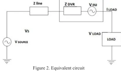
The equivalent circuit of DVR is shown in Fig 2.
Figure 2. Equivalent circuit
Now the injected voltage of DVR can be written as
Vdvr= VL+ ZLIL - VS --- (1)
A fault current in the grid can lead to a reduced magnitude of the voltage at the Point of Common Coupling. Under these circumstances, the DVR generates a compensating voltage corresponding to the estimated magnitude of voltage variation. This compensating voltage is injected to the distribution system via an injection transformer and it stabilizes the load side voltage.The voltage sag is detected and calculated error voltage is controlled and compared
with triangular waveform to produce PWM signals as shown in Fig 37KHPRGXODWLRQLQGH[LVDOZD\VP7KH
Figure 3. SPWM control for VSI
III.PROPOSED DVR SYSTEM
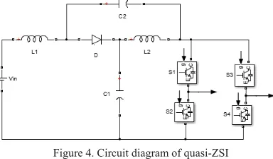
In proposed DVR system, PWM inverter is replaced by quasi-Z-source Inverter as shown in Fig 4. The qZSI has two types of operational states at the dc side: nonshoot-through states and shoot-through state. The LC and diode network connected to inverter bridge modifies the operation of the circuit, allowing the shoot through state.
Figure 4. Circuit diagram of quasi-ZSI
The major difference in qZSI compared to ZSI is it draws continuous current from the source and voltage on
capacitor C2is greatly reduced.
During a switching cycle T, non-shoot-through states intervals is T1 and shoot through period its interval is T0.
During non shoot-through state,
VL1= Vin-VC1, VL2= -VC2 and (2)
Vdc= VC1-VL2=VC1+VC2, VD=0 (3)
During shoot through state,
VL1= VC2+Vin, VL2=VC1 and (4)
Vdc= 0, VD=VC1+VC2 (5)
At steady state, average value of inductors over one switching cycle is zero. Applying this peak dc link voltage across inverter Bridge is
in n i dc
BV
V
T
T
v
0 ^2
1
1
(6)The peak inverter output voltage in boost mode is given by
BM
V
M
indc
V
V
2
.
2
^ ^
0
(7)
shoot-Figure 5. PWM technique of qZSI
Since the dc voltage is getting boosted, the output of inverter can be boosted even though the size of storage of element is reduced. In qZSI, the input current is continuous, lower capacitor rating and less EMI
problems
.
IV.SIMULATION AND RESULTS
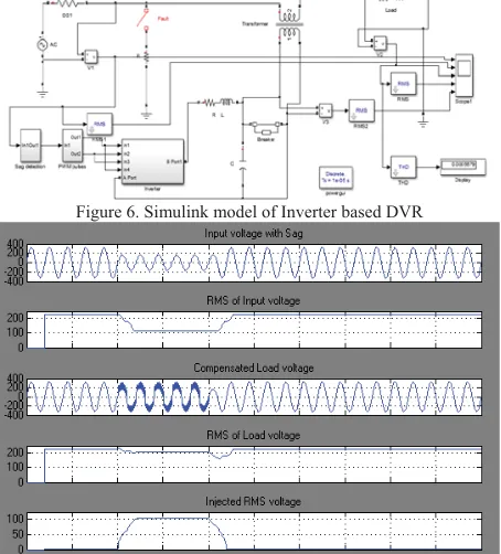
The simulation of VSI based and qZSI based DVR are carried out. Single phase test system is considered. Sag is generated by applying a fault in the line during interval 0.1-0.2 s. The 50% sag is detected and error signal is controlled and sine PWM pulses are generated so that inverter produces missing voltage. The fig 6 shows SIMULINK model of VSI based DVR. The sag is detected during interval 0.1-0.2s and rms value of the input is reduced to120V. The controller takes the action on error signal and SPWM pulses for inverters are produced by comparing the triangular wave with reference wave. The inverter gives the missing voltage 120V and the constant DC input required is 230V. The figure 7 shows compensated load voltage and injected voltage is observed to be 120V.
Figure8: PWM pulses in VSI
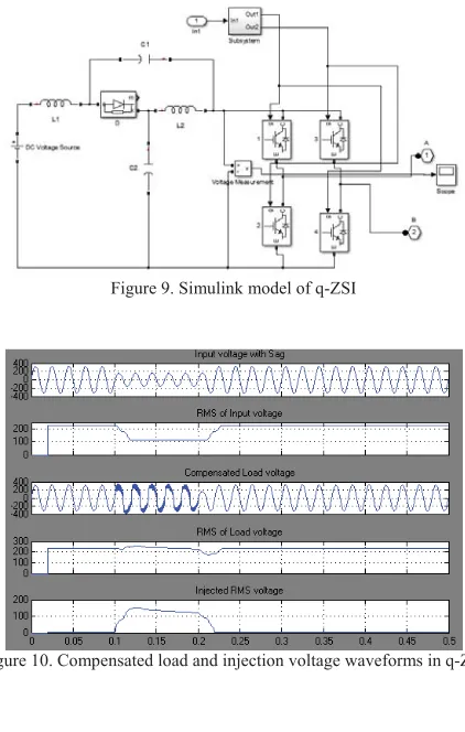
In the proposed system, the VSI inverter is replaced by quasi-Z source inverter as shown in Fig.9 L1=L2=5mH; C1=C2=470μF.The sag is detected during 0.1-0.2s and the error signal is generated and pulses are generated during shoot through states also.
If the triangular waveform is greater than Vp and Vn, shoot through state exists and input dc voltage is
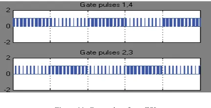
boosted by use of impedance network then the inverter output is also boosted. The inverter gives 120V for 50% sag and input DC required is 60V. The figure 10 shows compensated load voltage and RMS value of output. The gate pulses are also shown in Fig11.
Figure 9. Simulink model of q-ZSI
Figure 11. Gate pulses for q-ZSI
V..CONCLUSION
In this paper conventional system of Dynamic Voltage Restorer techniques were studied and a new method has been proposed which is more efficient and cost-effective since the size of DC storage element requirement is reduced. The proposed qZSI has merits such as wide range of gain, continuous input current, reduced component stress and lower component rating. The Simulation results show that qZSI based DVR is effective than conventional system. The proposed qZSI can be used in PV power generation and PV power can be utilised for power quality problems.
REFERENCES
[1] N.Hingorani, ”Introducing CUSTOM POWER,” IEEE SPECTRUM, Vol. 32, No. 6, pp. 41-48, June 1995 [2] IEEE std. 1159-2001R, “IEEE Recommended Practice for Power Quality Monitoring”, 2001
[3] Woodley N. H, Morgan L, and Sundaram A (1999) “Experience with an inverter-based dynamic voltage restorer,” IEEE Trans. Power Delivery, vol. 14, pp. 1181-1186.
[4] J. G. Nielsen, M. Newman, H. Nielsen, and F.Blaabjerg, “Control And testing of a dynamic voltage restorer (DVR) at medium Voltage level”, IEEE Trans. Power Electron, vol. 19, no. 3,pp: 806, May 2004.
[5] Omar R, Rahim N, Sulaiman M (2009) Modelling and simulation for voltage sags/swells mitigation using dynamic voltage restorer. , Journal of Theoretical and Applied Information Technology, 464–470
[6] Choi S. S, Li B. H, and Vilathgamuwa D. M (2000) “Dynamic voltage restoration with minimum energy injection,” IEEE Trans. Power Systems, vol. 15, pp. 51-57.