Abstract—The theme of this article is to apply a three-dimensional fully-nonlinear hydrodynamic model to simulate a solitary wave passing through a gap into a canal of expanded cross-section with a raised channel bottom. When a solitary wave impacts on an infinitely long breakwater with a gap width L1, part of the wave energy is reflected by the breakwater and part is transmitted through the gap. Here the domain with incident and reflected waves is called Region I and that with transmitted waves in a channel of width L2 (L2>=L1) is Region II. As the bottom of Region II has an upward step, the wave is transitioned to propagate from a deep water region (normalized depth=1) into a shallow water region (depth=D). The transmitted waves are subject to be diffracted and reflected by the confined boundaries. These diffraction and reflection effects are governed by D and L2. For L2=L1, it is similar to the case for a solitary wave climbing upon a step to generate soliton fission phenomenon. The results show that the condition of D>0 can enhance the nonlinearity of waves while L2>L1allows the transmitted waves to expand with reduced wave height. It is noticed that part of the transmitted outward-propagating waves are reflected back from the wall boundaries to interact with longitudinal traveling waves forming a wave front oscillating transversely with nonuniform wave height across the channel.
Index Terms—Solitary wave, fully-nonlinear wave, three-dimensional wave, diffraction, tsunami.
I. INTRODUCTION
Deformations of nonlinear long waves, such as a tsunami wave propagates over a three-dimensional continental shelf into a river, a bay or an estuary with a confined cross-section, are problems concerned for coastal environments. They are also important to both the fundamental studies and practical applications. This article addresses a study of applying a three-dimensional fully-nonlinear wave model to simulate an incident solitary wave encountering a breakwater with a gap into a channel with a raised bottom. This wave-structure interaction process indicates that part of the incident waves is reflected back while part is transmitted into the confined shallower water region. The wave transformation process includes simultaneously the wave diffraction, reflection, and transmission.
In the past, for shallow-water waves, it is applicable theoretically to neglect the effect of vertical variation by
Manuscript received January 20, 2014; revised March 7, 2014. This work was supported in part by the National Science Council of Taiwan under contract NSC102-2221-E-275 -001 -MY2.
C. H. Chang is with the Department of Information Management, Ling-Tung University, Taichung, Taiwan (e-mail: changbox@ teamail.ltu.edu.tw).
K. H. Wang is with the Department of Civil and Environmental Engineering, University of Houston, Houston, TX, USA (e-mail: [email protected]).
using the depth-averaged variables. Those quasi-three-dimensional based models have been widely utilized to perform simulations for a number of three-dimensional wave problems. With the introduction of a depth-averaged velocity potential, a popular, the so-called, generalized Boussinesq (gB) model was proposed by Wu (1981) [1]. The diffraction of solitary waves meeting a straight or inclined, thin breakwater in water of uniform depth has been studied numerically by Wang (1993) [2] using gB model and experimentally by Liu (1984) [3]. For problems with variable topography, Peters (1966) [4] developed a theoretical model to describe solitary waves propagating in channels of arbitrary cross-section. Peregrine (1967) [5] derived a classical Boussinesq model for long waves in water of varying depth in two horizontal dimensions. He also investigated both numerically and analytically the case of a solitary wave on a beach of uniform slope. Later, Shuto (1974) [6] extended the Korteweg-de Vries (KdV) model to study long waves in rectangular channels of variable depth and width. Chang et al. (1979) [7], with the added experimental measurements, utilized Shuto’s equation to investigate numerically on solitary waves moving along a rectangular channel with a linearly varying width but a uniform depth. Teng and Wu (1992) [8] applied two theoretical wave models, namely the generalized channel Boussinesq (gcB) and the channel Korteweg-de Vries (cKdV) models, to evaluate the general features of solitary and cnoidal waves propagating in a uniform channel of arbitrary shape. Their work was later extended by [9] to study the evolution, transmission and reflection of long water waves propagating in a convergent-divergent channel of arbitrary cross-section. Solutions between the two models were compared extensively. In the present study, we assume that there exists a shelf of abruptly raised bottom in the connected canal behind a breakwater with a gap. The related problems of solitary wave fission on a shelf have been investigated by many researchers in last two decades. The fission process that separates an incident solitary wave into a sequence of solitary waves with amplitude in decreasing order after climbing upon a two-dimensional (2D) shelf was presented in numerical solutions and laboratory measurements by [10]. The wave fission in a three-dimensional canal with an uneven bottom and a wider channel width has been noticed to be very different from that in 2D case.
In most of the previous studies, the wave models were based on weakly nonlinear and weakly dispersive assumptions. Recently, these restrictions have been overcome by solving the complete three-dimensional (3D) nonlinear equations. For example, Chang and Wang (2011) [11] developed a 3D curvilinear grid model to reveal the fully
A Solitary Wave Propagates through a Gap into a Channel
with an Upward Step
nonlinear transient waves generated by a moving object in water of constant depth. Here, we extend this model to simulate the problem of a solitary wave propagating through a gap of a breakwater system into a canal with variable width and water depth.
L1 wave L 2 Region I Region II Depth=1 Depth=1-D x y
Fig. 1. Schematic diagram of the modeling domain in top view.
II. MATHEMATICAL MODEL
A schematic diagram showing an incident wave propagating past a breakwater with a gap is illustrated in Fig. 1. A three-dimensional fully nonlinear water wave model is applied to solve the wave-breakwater interaction problem. We choose (x, y) as a coordinate system for the horizontal plane and z as a vertical coordinate pointing upwards. The fluid motion is assumed to be three-dimensional and irrotational and the fluid inviscid and incompressible. We neglect the effect of surface tension. The physical variables are nondimensionalized using the still water depth h in Region I, gravitational constant g and the fluid density as the reference variables. Hereinafter, all variables are conveniently defined as the dimensionless ones. The wave patterns depend on the incident wave height ( ), gap opening (L1), channel width (L2) and height of bottom step (D) in water region II. Under the assumption of ideal flow, the wave motion described by the velocity potential (x,y,z;t) satisfies the Laplace equation
0
yy zzxx
(1) Initially, the water region is undisturbed, that is 0.) ; , (x yt
is the free-surface elevation and the fluid-particle velocity is defined as (u,v,w)=(x,y,z).
The exact nonlinear conditions on the free surface are considered. The kinematic and dynamic free-surface conditions are
y x
t u v
w (2)
0 2
/ )
( 2 2 2
u v w P
t
(3)
where P is the atmospheric pressure on the free surface and is set as zero in the equaton.
The initial conditions of solitary wave profile and velocity potential are combined from [1] and [2]. Wang (1993) [2] indicated the free surface ( ) and the depth-averaged velocity potential ( ) for right going waves can be specified respectively as:
sech ( ) sech4 ( 0)
0 2
11 k xCtX k xCtX
(4)
) (
tanh )
,
(x z 4 3 k xCtX0
(5)
where k 3 [4(1)], C 1 = wave celerity, and X0= initial position of wave peak. Wu (1981) [1] derived a formulation describing the relationship between the original velocity potential () and the depth-averaged velocity potential ( ) as
) ( ) 2 3 1 ( ) ,
( 2 5
2
x z zz O (6)
In which water depth/wave length. Substitution of (5) into (6) leads to the equation at t=0
)] ( h sec ) ( [ ) ( tanh ) , ( 0 2 2 3 2 2 0 2 1 3 4 X x k z z k X x k z x (7) Therefore, (4) and (7) are adopted to characterize the incident wave in numerical simulations. The simulation domain is bounded in the region of x
[
xmin,
xmax]
andmin max
[
,
]
y y y . A set of out-going simple wave equations are chosen as the open boundary conditions to radiate all primary and scattered waves out of the lateral boundaries. On the bottom, and wall, impermeable solid boundaries, we impose that the rate of potential value toward the normal direction is equal to zero, that is
0 n (8) where
n
is the unit normal vector.III. NUMERICAL SCHEME
Two unknown variables are calculated in the present model. One is the velocity potential (
), and the other is the free surface elevation ( ). The transient curvilinear coordinate system is applied in this model. All variables in Cartesian grid (x, y, z) are transformed into general Curvilinear grids (,,). To conform the free surface, thecoordinate transformation is simplified to only apply along the vertical direction, such thatzz(,,;), while the horizontal coordinates remain uniformly distributed with
) ( x
x and yy() . Here, grids along the x and y directions are independent of time. Also, x x and
y
y . The Laplace equation (1) can be transformed from
the physical domain to the computational domain as
0 2 2 2 3 2 1 23 13 12 33 22 11 f f f g g g g g g (9)
where the geometric coefficients gijandfi can be referred in Chang and Wang (2011) [11].
transformed domain are given as
z w
y y
z z v
z x z x u
z y x
) ( ) (
) ( ) (
(10)
For the free-surface boundary conditions (2)-(3), after coordinate transformations, we have
) ( )
(
wu x v y (11)
0 )
( 2
1 2 2 2
w u v w P
(12)
-20 -15 -10 -5 0 5 10 15 20
x
0 5 10 15 20 25 30
y
A B
C D
WAVE
Fig. 2. Sketch of gauge positions for a solitary wave meets a semi-infinite breakwater.
-0.1 0.0 0.1 0.2 0.3 0.4
z
-0.1 0.0 0.1 0.2 0.3 0.4
z
-0.1 0.0 0.1 0.2 0.3 0.4
z
0 5 10 15 20 25
t -0.1
0.0 0.1 0.2 0.3 0.4
z
(A)
(B)
(C)
(D) -0.1
0.0 0.1 0.2 0.3 0.4
z
-0.1 0.0 0.1 0.2 0.3 0.4
z
-0.1 0.0 0.1 0.2 0.3 0.4
z
0 5 10 15 20 25
t
-0.1 0.0 0.1 0.2 0.3 0.4
z
(A)
(B)
(C)
(D)
Fig. 3. Comparisons between the computed (dashed line by Wang, 1993; solid line by present model) and recorded (line with dot by Liu, 1984)
elevations of the free surface at two locations.
TABLE I: FOUR STUDIED CASES IN PRESENT ARTICLE
Study cases L1 L2 D
Case I 15 15 0
Case II 15 15 0.5
Case III 15 60 0
Case IV 15 60 0.5
In this model, the finite-difference method is used to discretize the partial differential equations, then iterate through the numerical time steps to satisfy the governing equation and boundary conditions. The converged criteria of variables are set to be 10-6. We apply the boundary-fitted grid to conform the moving free surfaces and the uneven bottom. In this paper the grid spacings are set as x 0.25, y=0.5,
and z0.1. The time increment is equal to 0.1.
IV. RESULTS AND DISCUSSIONS
When L1 and L2 are large enough, it becomes a particular case for waves pass through a single breakwater, as shown in Fig. 2. Liu (1984) [3] investigated the diffraction problem of a solitary wave interacting with a single breakwater using both the linear-wave theory and the experimental measurements. Later, Wang (1993) [2] solved the generalized Boussinesq (gB) equations numerically to model Liu’s problems. Wave profiles at one position in front of the breakwater and the other at the shelter region (Fig. 2) are compared. Wang’s gB solutions showed a better agreement with experimental results than those of linear-long-wave theory. In present study, we use the developed fully nonlinear model to simulate this wave diffraction problem having the same conditions as one of Liu’s experiments. The computational domain is arranged as -20
x
20 and 0
y
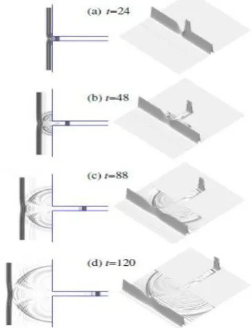
32. The peak of a given incident solitary wave with α=0.3 is initially situated at X0=-10.0. The time histories of computed wave elevations at the gauge’s locations are compared with the gB solutions of [2] and the experimental data of [3] in Fig. 3. Generally speaking, the present results for the wave height of the reflection wave (eg. the second wave in Fig. 3a) and the main wave in the shelter region (see Fig. 3b) are shown to have a better agreement with Liu’s data. It indicates the assumptions of weak nonlinearity and weak dispersion in gB model can demonstrate to have mostly well representation of the wave filed, however with a little deviation from the laboratory data. The present fully nonlinear model can improve the wave prediction especially the wave height.Fig. 4. Wave pattern for a solitary wave with =0.2 passes through an opening L1=L2=15, and D=0 at t=24, 48, 88 and 120. Here the left plots are
top view; and the right figures are three-dimensional perspective view plots.
With the above described model verification, this model is convinced confidently to apply for the wave transformation
ζ ζ
(a)
studies indicated in Fig. 1. The results for four cases, as listed in Table I, are presented here. The conditions of incident wave height of =0.2 and gap opening L1=15 were set to be the same for all four cases. Only the canal width L2 and the height of canal bottom step D were given with different values. Case1 and Case 2 are concerned with the influence of D when L1 equal to L2. It depicts how the step influences the wave propagation in the canal as a solitary wave entering a gap into a canal with a same width as the gap opening. In addition, Case 3 and Case 4 are arranged as L2 being larger than L1 for considering the cases with abrupt expansion of the canal width and including or not including the effect of D. For the present study cases, the results for step with D=0, or 0.5; and L2=15 or 60 are discussed here. Computation domain is confined within (xmin, xmax)=(-130, 130), (ymin, ymax)=(-110,110). The incident solitary wave is located at the position X0=-15 in front of the breakwater.
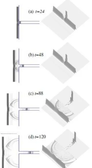
Fig. 5. Wave pattern for a solitary wave with =0.2 passes through an opening L1=L2=15, and D=0.5 at t=24, 48, 88 and 120. Here the left plots are
top view; and the right figures are three-dimensional perspective view plots.
The contour plots that reveal the top views of wave pattern are used to describe the evolution of wave scattering. The left part of Fig. 4 shows the top view of gray-level contour plots of wave elevations at t=24, 48, 88, and 120 for a solitary wave passing through a breakwater gap with opening L1=15 into a canal having the same depth (i.e. D =0) and L2=15. Also shown on the right part of Fig. 4 are the corresponding three-dimensional perspective view plots of the wave patterns. It illustrates the crest line of the solitary wave encountering the parallel breakwater where a narrow opening allows a small portion of the incident waves to be transmitted into the downstream channel (t=24, see Fig. 4a). Later (t=120, see Fig. 4d), the wave pattern shows that the main wave is reflected back and two systems of cylindrical waves that
follow the reflected wave are generated from the corners of the opening creating crosswise interaction. The main transmitted wave maintain as a solitary wave with some emerged trailing waves. When canal has a step with D values the results are shown to have very different wave patterns. For the Case II with a step D=0.5 (see Fig. 5), the shallow-water depth results in an increase in the steepness of transmitted waves. Wave fission showing the separation of main waves into three to four solitons with amplitude in decreasing order can be noticed. A series of wave profiles on the symmetrical plane y=0 at t=30, 60, 90, and 120 are selected to plot in Fig. 6. The results of Case I with D=0 are presented in Fig. 6a. The transmitted waves in the channel are shown to have slightly higher amplitude than that of the initial one due to waves converge into a more confined flow region. The main wave followed with some small tailing oscillation retains the solitary wave properties. Fig. 6b shows the transmitted wave that climbs over a step to increase its steepness splits into a series of solitary waves. The results are similar to a vertical two-dimensional case for a solitary wave passing over a semi-infinite step. The numbers of wave fission are related to the step height and incident wave height. Readers can refer detail discussions in Seabra-Santoes et al. (1987) [10] and experimental work of Losada et al. (1989) [12].
transmitted wave (a) D=0
(b) D=0.2
-120 -90 -60 -30 0 30 60 90 120 x
-0.10 0.00 0.10 0.20 0.30 0.40 0.50
y
(c) D=0.5
t=30 60 90 120
-0.10 0.00 0.10 0.20 0.30 0.40 0.50
y
t=30 60 90 120 t=30
60 90 120
-0.10 0.00 0.10 0.20 0.30 0.40 0.50
y
t=30 60 90 120
t=30 60 90 120
reflected wave
t=30 60 90 120
transmitted wave (a) D=0
(b) D=0.2
-120 -90 -60 -30 0 30 60 90 120
x
-0.10 0.00 0.10 0.20 0.30 0.40 0.50
y
(c) D=0.5
t=30 60 90 120
-0.10 0.00 0.10 0.20 0.30 0.40 0.50
y
t=30 60 90 120 t=30
60 90 120
-0.10 0.00 0.10 0.20 0.30 0.40 0.50
y
t=30 60 90 120
t=30 60 90 120
reflected wave
t=30 60 90 120
Fig. 6. Free surface profiles on plane y=0 at t=30, 60, 90, and 120 for =0.2 passes through an opening L1=15, L2=15. (a) D=0; (b) D=0.5.
As L2=60, it represents a channel with a sudden expansion of the width. The wider channel allows the main transmitted waves to expand more widely with gradual decrease of wave amplitude along the transverse direction. In addition, the transmitted, outward-propagating waves are subject to oblique reflection by two side walls to form a sequence of wave-wave interactions including with the longitudinal traveling waves. The lateral-wall effect can increase the wave height of the transmitted leading wave.
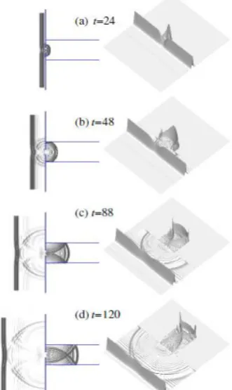
For D=0 (Fig. 7), the wave amplitude is shown to suddenly decrease when wave enters through a gap into a wider region. Moreover, two systems of waves continually reflected from
(a)D=0
side-walls to collide obliquely from each other and to interact with longitudinal traveling waves. This wave-wave interaction process results in the increase of wave height. It appears two to three main wave crests (shown on the grey-level contour plot) followed with a series of oblique wave interaction pattern are observed in Region II. For D=0.5 (Fig. 8), the wave nonlinearity in the shallower-water depth region increases to split the transmitted wave into a series of solitary waves. Comparison with the case of D=0 in Fig. 7, although the transmitted wave height is shown to increase for D=0.5, its celerity decreases due to the effect of shallower water depth. Furthermore, the transmitted wave front showing transverse oscillation with nonuniform wave height across the channel can be noticed. At t=120, the amplified wave height of the transmitted leading wave adjacent to the channel walls is observed.
Fig. 7. Wave pattern for a solitary wave with =0.2 passes through an opening L1=15, L2=60, and D=0 at t=24, 48, 88 and 120. Here the left plots
are top view; and the right figures are three-dimensional perspective view plots.
The wave profiles on the plane y=0 at t=30, 60, 90, and 120 for Case IV are plotted in Fig. 9. It shows as the transmitted waves spread in a wider region, the wave heights decrease. Furthermore, the transmitted waves are gradually deformed as a result of side-wall effects to lose the similarity of solitary waves (Fig. 9a). However, with the inclusion of the effect of the upward step, the increased nonlinearity can balance the dispersion to restore the leading wave front to propagate as a solitary wave (see Fig. 9b). To compare with Fig. 6, it also reveals the free-surface elevations in transmission are scattered no longer above the still water level.
Fig. 8. Wave pattern for a solitary wave with =0.2 passes through an opening L1=15, L2=60, and D=0.5 at t=24, 48, 88 and 120. Here the left plots
are top view; and the right figures are three-dimensional perspective view plots
transmitted wave (a) D=0
(b) D=0.2
-120 -90 -60 -30 0 30 60 90 120
x
-0.10 0.00 0.10 0.20 0.30 0.40 0.50
y
(c) D=0.5
t=30
-0.10 0.00 0.10 0.20 0.30 0.40 0.50
y
t=30 t=30 60 90 120
-0.10 0.00 0.10 0.20 0.30 0.40 0.50
y
t=30 60 90 120
t=30 60 90 120
reflected wave
t=30
60 90
90 90
60 60
120
120
120 transmitted wave (a) D=0
(b) D=0.2
-120 -90 -60 -30 0 30 60 90 120 x
-0.10 0.00 0.10 0.20 0.30 0.40 0.50
y
(c) D=0.5
t=30
-0.10 0.00 0.10 0.20 0.30 0.40 0.50
y
t=30 t=30 60 90 120
-0.10 0.00 0.10 0.20 0.30 0.40 0.50
y
t=30 60 90 120
t=30 60 90 120
reflected wave
t=30
60 90
90 90
60 60
120
120
120
Fig. 9. Free surface profiles on plane y=0 at t=30, 60, 90, and 120 for =0.2 passes through an opening L1=15, L2=60. (a) D=0; (b) D=0.5.
V. CONCLUSIONS
A fully 3D model capable of simulating the wave transformation phenomena involving the propagation of a solitary wave passing through a gap of a breakwater into a channel with or without an upward step is presented in the study. The effect of different channel width is also investigated. For a relative small gap, it is revealed that most part of propagating waves (away from the opening) is fully
reflected back by the breakwater with a portion of waves (near the opening) enters the transmission zone. Two system of cylindrical waves generated from the two tips of breakwaters interact each other. The evolution of the transmitted waves is affected by the width and the depth of the canal. For the cases of same canal width as the gap opening (L1=L2), if D=0, the entering wave, compared to the incident waves, is converged into a more confined fluid region to increase its amplitude in leading wave with some trailing waves followed to propagate toward downstream. After a longer time, its leading wave recovers as a solitary wave propagating in a canal of uniform depth. For D=0.5, the entering wave with its increase of wave height splits into a sequence of solitons with amplitude in decreasing order. For a wider channel (L2>L1), the entering wave is dispersed. Also, the transmitted outward- propagating waves are subject to oblique reflection from lateral walls to increase the height of wave crest after wave-wave interaction. For D=0.5, the transmitted wave front with nonuniform wave height is found to oscillate along the transverse direction. Amplified wave elevations adjacent to the channel walls are also observed. This phenomenon can be critical to the design of the channel and is a safety concern to the region close to the channel walls.
REFERENCES
[1] T. Y. Wu, “Long waves in ocean and coastal waters,” Journal of. Engineering Mechanics Division, ASCE, vol. 107, no. 3, pp. 501-522, 1981.
[2] K. H. Wang, “Diffraction of solitary waves by breakwaters,” Journal of Waterway, Port, Coastal and Ocean Engineering, vol. 119, no. 1, pp. 49-69, 1993.
[3] P. L. F. Liu, “Diffraction of solitary waves,” Journal of Waterway, Port, Coastal and Ocean Engineering, vol. 110, no. 2, pp. 201-214, 1984.
[4] A. S. Peters, “Rotational and irrotational solitary waves in a channel with arbitrary cross section,” Commun. Pure Appl. Maths., vol. 19, pp. 445-471, 1966.
[5] D. H. Peregrine, “Long waves on a beach,” Journal of Fluid Mechanics, vol. 27, pp. 815-827, 1967.
[6] N. Shuto, “Nonlinear long waves in a channel of variable section,”
Coastal Engng Japan, vol. 17, pp. 1-12, 1974.
[7] P. Chang, W. K. Melville, and J. W. Miles, “On the evolution of a solitary wave in a gradually varying channel,” Journal of Fluid Mechanics, vol. 95, pp. 401-414, 1979.
[8] M. H. Teng and T. Y. Wu, “Nonlinear water waves in channels of arbitrary shape,” Journal of Fluid Mechanics, vol. 242, pp. 211-233, 1992.
[9] M. H. Teng and T. Y. Wu, “Evolution of long water waves in variable channels,” Journal of Fluid Mechanics, vol. 266, pp. 303-317, 1994. [10] F. J. Seabra-Santos, D. P. Renouard, and A. M. Temperville,
“Numerical and experimental study of the transformation of a solitary wave over a shelf or isolated obstacle,” Journal of Fluid Mechanics, vol. 176, pp. 117-134, 1987.
[11] C. H. Chang and K. H. Wang, “Generation of three-dimensional fully nonlinear water waves by a submerged moving object,” Journal of Engineering Mechanics, ASCE, vol. 137, no. 2, pp. 101-112, 2011. [12] M. A. Losada, C. Vidal, and R. Medina, “Experimental study of the
evolution of a solitary wave at an abrupt junction,” Journal of Geo. Res., vol. 94, pp. 14557-14566, 1989.
Chih-Hua Chang is an associate professor of the Department of Information Management at Ling-Tung University in Taiwan. He earned a Ph.D. degree in 1997 in the Department of Hydraulic and Ocean Engineering of National Cheng Kung University, Taiwan. He has been at Ling-Tung University since 2003. Dr. Chang’s research interests include geographic information system, coastal and ocean engineering, and computational fluid dynamics.