N
S
Available online at: www.ijcncs.orgISSN 2308-9830
One Way Direction Communication Synchronization for WideMac
Protocol in IR-UWB based WSN
Anouar Darif1, Rachid Saadane2, Driss Aboutajdine3
1,3
LRIT-GSCM Associated Unit to CNRST (URAC 29) FSR, Mohammed V-Agdal University, BP 1014
Rabat, Morocco
2
SIR2C2S/LASI-EHTP, Hassania School of Public Labors Km 7 El Jadida Road, B.P 8108, Casa-Oasis,
Casablanca, Morocco
E-mail: [email protected], [email protected], [email protected]
ABSTRACT
IR-UWB technology as a next generation of the IEEE802.15.4 standard is a promising solutions for WSN due to its various advantages such as its robustness to severe multipath fading even in indoor environments, its low cost and complexity, and low energy consumption. To implement such a solution, we need a suitable Mac protocol to exploit the specific features of this technology. WideMac was presented as a novel MAC protocol designed for wireless sensor networks using impulse radio ultra wide band transceivers due to its low power consumption. Because of the luck of synchronization in this protocol, this paper will present a solution for the synchronization problem when there is only one way direction communication.
Keywords: WSN, IEEE802.15.4A, IR-UWB, WideMac, Synchronization, Packets delivery.
1 INTRODUCTION
Wireless Sensor Networks (WSN) has emerged as an important area for research and development. Though WSN is in its early stages, its impact is envisaged to be far reaching, from daily life, to remote monitoring [1] of environment, habitat, agriculture health care [2], automobiles[3], hazardous zones, disaster prone zones, defense applications to probing of planets. Moreover they can be used for monitoring as well as control. In fact, they form the basic constituent of ubiquitous sensing, communication, computing, and control [4].
Recent advances in sensing, computing and communication technologies coupled with the need to continuously monitor physical phenomena have led to the development of Wireless Sensor Networks (WSNs). WSN consist of four main components: A radio, a processor, sensors and battery. A WSN is formed by densely deployed sensor nodes in an application area. In most deployments, the sensor nodes have self-organizing capabilities, to form an appropriate structure in
order to collaboratively perform a particular task. Wireless Sensor Networks are found suitable for applications such as surveillance, precision agriculture, smart homes, automation, vehicular traffic management, habitat monitoring, and disaster detection [5].
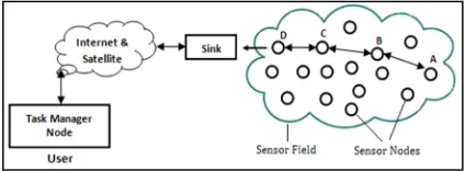
The sensor nodes are usually scattered in a sensor field as shown in Figure 1. Each of these scattered sensor nodes has the capabilities to collect data and route data back to the sink and the end users. Data are routed back to the end user by a multi hop infrastructure less architecture through the sink. The sink may communicate with the task manager node via Internet or Satellite.
Impulse Radio Ultra Wide Band (IR-UWB) is a good candidate for wireless sensor network due to its various benefits [6]. To implement such a solution, we need a suitable Mac protocol in MAC layer to exploit the specific features and advantages of this new technology.
The present paper is organized as follows. In Section 2 we introduced IEEE802.15.4a standards. In section 3 we presented the WideMac protocol. Section 4 presents the synchronization procedure. The simulation and its results are presented in section 5; finally, Section 6 concludes the paper.
2 IEEE802.15.4A STANDARD RELATED WORK
In 2004, the IEEE established the standardization group IEEE 802.15.4a, with the mandate to develop a new physical layer for applications such as sensor networks. The goal of the 802.15.4a standard is to provide an enhanced communications capability to the 802.15.4-2006 standard, and also provide device ranging to enable geo- location capability for a system. One option of this standard is based on UWB transmission techniques, namely time-hopping impulse radio (TH-IR). The group first developed application scenarios, from which the requirements for the capabilities of the physical layer and channel models were deduced. In March 2005, a baseline proposal [7] was approved, and in the subsequent months, a number of subgroups developed the details of the modulation/coding schemes, multiple access, ranging waveforms, and required modifications of the MAC layer [8].
2.1 IEEE802.15.4A Physical layer
IR-UWB signals are transmitted in form of very short pulses with low duty cycle (Figure 2). IR-UWB is a promising technology to address Wireless Sensor Network constraints. However, existing network simulation tools do not provide a complete WSN simulation architecture, with the IR-UWB specificities at the physical (PHY) and the Medium Access Control (MAC) layers.
The physical layer signal generated by each transmitter is a classic IR-UWB signal with time-hopping (TH) as in [9] (see Figure 2): time is divided into frames of duration Tf and there is one
pulse transmitted per frame. Because the pulses are sent infrequently, several transmitters can share the medium concurrently. However, the transmission time of each pulse is randomized to avoid catastrophic collisions.
Hence, a frame is further subdivided into Nc
non-overlapping chips; for each frame, these chips define the possible locations for the transmission of
a pulse. To avoid inter-symbol interference (ISI) due to the multipath propagation channel, a guard time reduces the number of effective available positions by Ng chips to Nc - Ng. At last, a sequence
is subdivided by Nfframes.
Fig. 2. Classic IR-UWB signal [1] and its parameters: Tc is the duration of a chip, Tf = Nc.Tc is the duration of a frame and Ts = Nf.Tf is the duration of a sequence. Tg
= Ng.Tc is guard time used to prevent ISI.
A so-called pseudo-random time-hopping sequence (THS) of integers uniformly distributed in [0, Nc – Ng - 1] indicates which position to choose in each frame for the transmission of a pulse. Hence, each transmitter has its own THS, which is independently generated. Information is transmitted thanks to binary pulse position modulation (BPPM), where the position of a pulse carrying a one is shifted by a duration Tm and the position of a
pulse carrying a zero is left unchanged. More formally, the baseband IR-UWB signal with BPPM of the nth transmitter is
S(n)(t) = ∑ ( − − ( ) − ( ) ) (1)
Where p(t) is a pulse, ( )is an element of the THS of transmitter n and ( ) in {0,1} is an information-bearing bit. In practice, the pulses of the IR-UWB signal generated by our transmitters [10] are simply square pulses of duration Tp up
converted at fc. For time-hopping, for complexity
reasons, we do not generate a continuous stream of time-hopping positions. Instead, for each transmitter, we generate a sequence of length Nf of
time-hopping positions and use this sequence repeatedly i.e.
( )
= ( ) . (2)
2.2 Channel Model
The path loss modeled [11] in dB is
( ) = 30 + 20.4 ≤ 11
30 + 74 − 56 > 11 (3)
frequency selective fading channel can be represented as
( ) = ∑ [ − ] (4)
where and have Rayleigh and uniform (over
[0, 2π]) distributions, respectively. Furthermore, we assume an exponential power-delay profile with parameter = 39.8 .
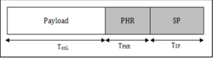
2.3 The Frame Format
In IEEE 802.15.4a networks, devices communicate using the packet format illustrated in Figure 3. It consists of three components: synchronization preamble (SP), PHY-header (PHR), and payload. The very short duration of the pulses makes them difficult to detect. Since there is no carrier signal, the channel is empty most of the time even though a transmission is ongoing. The only part of the signal that can be reliably detected (using a dedicated algorithm) is the synchronization preamble, with which all transmissions begin. It consists of a deterministic sequence of isolated pulses used by all devices that are part of the same network (two synchronization preambles are defined in the standard).
Fig. 3. The IEEE 802.15.4A UWB PHY Frame.
The energy consumption to transmit a packet once is the summation of two parts: EO, the energy
consumption on delivering the SP and PHR, and EL, the energy consumed on the payload.
We assume that the synchronization preamble has values {-1, 1} and is received coherently and PHR is modulated using DBPSK, always received coherently, and coded in the same manner as the payload. Therefore, the overhead energy consumption is
= ( )+ ( ) (5)
= + + +
where = + = ( + )/ (6)
is the fixed base data rate.
The energy consumption for the payload can be modeled as
= ( )+ ( ) (7)
Where ( )and ( ) represent the energy consumption totransmit/receive the payload containing LLinformation bits,respectively.
( )
is
( )
= + (8)
Where = / , is the time duration to transmit thepayload containing LLbits, and Rcis
the coding rate.
The energy consumption to receive LLinformation
bits is
( )
= ( + + + )
+ ( + ) (9)
3 WIDEMAC PROTOCOL
3.1 Presentation
WideMac was presented as a novel MAC protocol designed for wireless sensor networks using ultra wide band impulse radio transceivers [13]. It makes all nodes periodically (period TW,
identical for all nodes) and asynchronously wake up, transmit a beacon message announcing their availability and listen for transmission attempts during a brief time TListen.
Fig. 4. Detailed view of a WideMac period
Figure 4 illustrate a single period structure. It starts with a known and detectable synchronization preamble and is followed by a data sequence which announces the node address and potentially other information, such as a neighbor list or routing table information (for instance,
cost of its known path
to the sink). A small listening time follows
T
Listen, during which
the node stays in reception nmode and that allows it to receive a message [14]. The whole period composed of Tbeacon and TListen is
called Ta (time of activity); and its very small
compared to the time window TW. This period is
followed by a long sleeping period TSleep during
3.2 Power Consumption Models
Each normal TW interval starts with a beacon
frame transmission followed by a packet or a beacon reception attempt, during this start a node must enter transmission mode ( ),transmit its beacon ( ), switch to reception mode ( ) and attempt a packet reception ( ). These costs are regrouped in the beacon energy .
E = E + T P + E
+ T P (10)
In addition, during a time L, a node must some-times transmit a packet or receive one , and sleep the rest of the time , resulting to the following average power consumption:
P = (E + + E + E )
(11)
Where:
= . ( ). .
= . . .
= . .
K represents the message length in bytes, is the transmission power, CTx, CRx and CSleep
represent the current intensities for the three modes, TTx and TRx are the time of transmission and
reception.
4 SYNCHRONIZATION PROCEDURE
4.1 Problem
In order to transmit a packet, a source node in transmission phase must wait to receive the beacon of the destination node. If the source node fails to receive this beacon (especially when the destination node’s beacon is transmitted outside the active period of the source node), a breakdown in communication between the two nodes is caused in one direction during a considerable time interval.
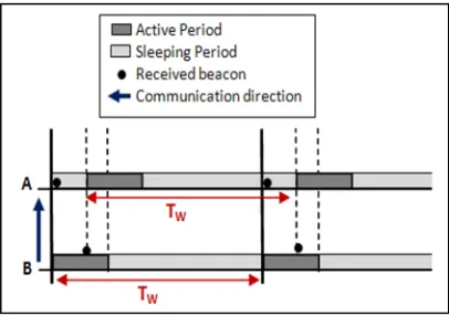
Figure 5 shows the one communication direction case (from node B to node A).
Fig. 5. One Way direction communication
This is normal, as in the presentation of WideMac, nodes wake up periodically and asynchronously to a static period TW common to all nodes in the network. Therefore a synchronization process between nodes is required to overcome these problems.
In this section, we present the lack of synchronization problem between nodes from which suffer the WideMac protocol and caused a one way direction communication. The neglect of this issue certainly has a cost in terms of performance, efficiency, and throughput of this protocol. This has been proven by simulation scenarios as shown in Figure 6. In this figure, for a scenario involving 24 nodes as well as the sink node deployed on a 5 * 5 grid network, we observe that six of 24 nodes did not send any packets to the sink node in a total number of 80 packets to send.
4.2 Synchronization Implementation
The exposed problem depicted in Figure 7 shows the case where there is a communication in one direction (from node B to node A). It shows that node A cannot send its data to node B since it cannot receive his beacon because of the time lag between their active periods.
Fig. 7. One way direction communication synchronization
Our solution is based on exploiting the fact that node B receives the beacon from node A, like this, node A wanting to transmit data to node B will encapsulate a synchronization request with it in its beacon. Once the node B receives this beacon containing a synchronization request to the node A, and depending on the receipt time of this beacon, node B will decide to launch a synchronization procedure: This procedure consist simply to calculate the time of its next wake up so that the its active period will be scheduled directly after the active period of node A. Like that a small time lag
∆T as shown in Figure 6 will be added to the sleeping period of node B. With this procedure, node A is synchronized with node B and can receive its beacon to start sending data packets to node B.
5 SIMULATION AND RESULTS
5.1 Simulation Platform
OMNeT++ is an extensible, modular, component-based C++ simulation library and framework which also includes an integrated development and a graphical runtime environment; it is a discreet events based simulator and it provides a powerful and clear simulation framework. MiXiM joins and extends several existing simulation frameworks developed for wireless and mobile simulations in OMNeT++. It provides detailed models of the wireless channel, wireless connectivity, mobility models, models for obstacles and many
communication protocols especially at the Medium Access Control (MAC) level. Moreover, it provides a user-friendly graphical representation of wireless and mobile networks in OMNeT++, supporting debugging and defining even complex wireless scenarios [15].
We used a tree based topology, where nodes transmit packets to a Sink node. Figure 8 show the network structure chosen in the 25 nodes’ number scenario, with a sink node in the corner.
Fig. 8. The 25 nodes' number scenario
5.2 Synchronization Parameters
As described above, TW is the characteristic wake
up period of WideMac. Ta is the nodes’ activity
time during which they are waiting for a data message or a beacon message.
The parameter maxTxAttempts represent the maximum number of frame retransmission and
macAckWaitDuration is the time to wait for an acknowledgement after transmitting a unicast frame. MSR (Maximum Synchronization Request) is the maximum number to request synchronization with a node; when MSR is reached, a synchronization retry is performed with the δ
parameter. It is the time lag for the wake up moment to be retrieved to seek communication in no-communication situation. MSS (Maximum Synchronization Sending) is the maximum number of beacons to generate with an IS flag set to true after a synchronization process.
Table 1: WideMac synchronization parameters
Parameter Value
Tw 0.04s
Ta -
δ -
MSR 4
MSS 10
maxTxAttempts 15
macAckWaitDuration 0.0004s
minBE 1
MaxBroadcastDataTx is the maximum number of data packets for broadcast to transmit during a TW.
minBE and maxBE are respectively the minimum and the maximum backoff exponent used in the backoff algorithm.
For WideMac synchronization parameters value see table 1.
5.3 Energy and Timing Parameters
We performed the simulations in the MiXiM2.1 release framework with the OMNeT++ 4.2 network simulator. We ran a simulations witch the network structure shown in Figure 8 with different parameters’ values to evaluate our proposed Synchronization mechanism.
For the energy consumption (see Table 2) we used the following radio power consumption parameters:
Table 2: Energy Parameters
Parameter Value
PRx 36.400 mW
PTx 1.212 mW
PSleep 0.120 mW PSetupRx 36.400 mW PsteupTx 1.212 mW PswTxRx 36.400 mW PswRxTx 36.400 mW
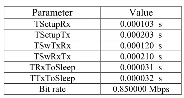
For the radio timing we used the parameters shown bellow in Table 3.
Table 3: Timing Parameters
Parameter Value
TSetupRx 0.000103 s TSetupTx 0.000203 s TSwTxRx 0.000120 s TSwRxTx 0.000210 s TRxToSleep 0.000031 s TTxToSleep 0.000032 s Bit rate 0.850000 Mbps
5.4 Results
The remarkable decrease in the performance of WideMac protocol with the increasing number of nodes is due to the problem of lack of communication between some nodes. This problem has been presented in section (4.1). This can be explained as some nodes cannot send their packets because they do not receive any destination nodes’ beacon.
Fig. 9. Packets delivery for the 25 nodes scenario
To overcome this problem, a synchronization (timing) mechanism has been implemented. Figure 9 clearly shows that this problem has been overcome by this synchronization mechanism since in the same simulation scenario (24 nodes) all nodes have sent more than 43 packets out of 80, and even 6 nodes out of 24 were able to send more than 80% of their packets. This figure clearly shows that the synchronization mechanism implemented in WideMac has solved the problem of lack of communication between some nodes in the network, and it still remains to be demonstrated with other simulation scenarios that will come after.
6 CONCLUSION AND FUTURE WORKS
To ensure an acceptable quality of service in any MAC protocol we were obliged to study the Packets delivery ratio. In this work we showed the remarkable improvement in terms of packets delivery ratio. These experiments prove the benefits of introducing the synchronization mechanism in the WideMac protocol for IR-UWB based WSN.
We aim, as a future work, to develop a new adapted routing protocol that will be paired with the WideMac’s synchronization mechanism to largely exploit the IR-UWB based WSN features.
7 REFERENCES
[1] A. Hua, H. Wangb and J. Wana, “Design of WSN-Based Remote Monitoring System for Environmental Parameters in Substation”, International Journal of Smart Grid and Clean Energy, June 30, 2012.
[3] J. Shukla, B. Kumari, “Security Threats and Defense Approaches in Wireless Sensor Networks: An Overview”, International Journal of Application or Innovation in Engineering & Management, Volume 2, Issue 3, March 2013. [4] S. Sharma and P. Mittal, “Wireless Sensor
Networks: Architecture, Protocols”, nternational Journal of Advanced Research in Computer Science and Software Engineering, Volume 3, Issue 1, January 2013.
[5] F. Akyildiz, T. Melodia, R. Chowdhury, “A survey on wireless multimedia sensor networks”, Journal of Computer networks (Elsevier) 2007; 51(4):921–60.
[6] R. Fisher et al., “DS-UWB Physical Layer Submission to 802.15 Task Group 3a”, IEEE 802.15-04/137r3,July2004.
[7] A. F. Molisch, et al, “UWB PHY proposal for IEEE 802.15.4a Alt-PHY Project”, tech. rep., 2005. doc.: IEEE 802.15-05-0172-02-004a. [8] IEEE Std 802.15.4a – 2007 (Amendment to
IEEE Std 802.15.4), IEEE
Computer Society, 31 August 2007.
[9] F. Haroon, H. Rasheed, K. M. Ahmed, “A Robust Reception of IEEE 802.15.4a IR-TH UWB in Dense Multipath and Gaussian Noise”, World Academy of Science, Engineering and Technology 2010.
[10]N. Rebhi, A. Kachouri, M. Samet and D. Fournier Prunaret, ”T-H Differential Pseudo-Random Pulse: ANew UWB System for LR-WPAN Applications”, Journal of Telecommunications, volume 12, issue 1, january 2012.
[11]D. Cassioli, M. Z. Win, and A. F. Molisch, “A statistical model for theUWB indoor channel”, Proc. Vehicular Technology Conference (VTC), 2001.
[12]B.V. Santhosh Krishna, “Ultra Wideband Channel Model for IEEE 802.15.4a and Performance Comparison of DBPSK/OQPSK Systems”, International Journal of Computer Science and Information Technologies, Vol. 2 (1) , 2011, 587-596.
[13]J. Rousselot, A. El-Hoiydi, J.-D. Decotignie, “WideMac: a low power and routing friendly MAC protocol for Ultra Wideband sensor networks”, IEEE International Conference on Ultra-Wideband, Vol 3 pp 105- 108 2008. [14]D. Piguet, J.-D. Decotignie, J. Rousselot, ”A
MAC protocol for micro flying robots coordination”, European Community’s Seventh Framework Programme (FP7/2007-2013) under grant agreement n 231855 .
[15]A.Köpke, M.Swigulski, K.Wessel, D. Willkom m, P.T.Klein Haneveld,T.E.V.Parker, O.W.Vis
![Fig. 2. Classic IR-UWB signal [1] and its parameters:](https://thumb-us.123doks.com/thumbv2/123dok_us/1324727.1640583/2.612.314.524.175.245/fig-classic-ir-uwb-signal-parameters.webp)