Design of Microstrip Patch Antenna Array With Unslotted and U-slotted Fractal
UC-EBG Structure
L.Keerthana1 and M.Jegajothi2
1PG Student, Department of Electronics and Communication Engineering, Alagappa Chettiar Government College of Engineering & Technology, Karaikudi. 2
Assistant Professor, Department of Electronics and Communication Engineering, Alagappa Chettiar Government College of Engineering & Technology, Karaikudi, India.
Article Received: 01 March 2018 Article Accepted: 09 April 2018 Article Published: 28 April 2018
1. INTRODUCTION
Microstrip antenna became very popular in the today worlds of wireless communication system. They are used for
government and commercial applications to transfer the information from one place to another [1]-[2]. Microstrip
antenna basically consist of a substrate
radiating
patches and ground [3]. Often the microstrip antennas are alsocalled as patch antennas. The ground plane is placed at the bottom of the substrate and the two radiating patches and
the feed lines are usually photoetched on the dielectric substrate [4].
Microstrip patch antennas are required for smart features such as low profile, light weight, low cost, high efficiency
[5]. The two rectangular patches are most widely used configurations, due to suffer from the narrow bandwidth.
Isolation improvement in antenna array poses complicated result in the antenna community. In antenna arrays,
multiple antenna elements operate to designed at the same frequency to a common substrate, so that mutual
coupling occurs and also it reduces the antenna gain, bandwidth and radiation efficiency [6].
In this paper, design of microstrip patch antenna array with fractal UC-EBG structure and u-slot is presented. First,
unslotted fractal UC-EBG microstrip patch antenna and three cross slots is analyzed and the U-shaped slot is cut in
the microstrip patch antenna [7]. A row of fractal UC-EBG structure and U-slots as the decoupling structures
applied in the antenna array are proposed to improve isolation of the antenna array significantly. Also, the spacing
between the two patch elements is obviously reduced [8].
Finally, the measured results show that the isolation is 30.28 dB and -30.94 dB with in the operating bandwidth [9].
The objective of this work is to design and developed U-shaped microstrip patch antenna, which can work both the
frequencies as 6 GHZ and 9.2 GHZ enhances the return loss of -10 dB. The obtained frequency is useful for C and A B S T R A C T
X band applications such as Wi-fi, Wi-max and aircraft, spacecraft, RADAR applications. The proposed antenna
were designed and simulated by using ANSYS HFSS (version 15.0) simulation software.
2. ANTENNA DESIGN AND CONFIGURATIONS
The concrete shape of the proposed UC-EBG unit cell structure is shown in the Fig 1. The fractal UC-EBG
structure is placed on the Moore curve. The total length of the unit cell are ensured, the specific values like line
width y and the spacing between the lines x can be determined.
Fig :1. Geometry of the fractal UC-EBG unit cell
2.1. Unslotted fractal UC-EBG structure
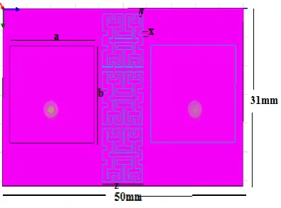
To analyze the performance of the unslotted fractal UC-EBG, an antenna array (1×2) is presented. The substrate
with a high dielectric constant of 10.2,loss tangent of 0.003 is employed in the antenna array. The geometry of the
antenna array with the unslotted fractal UC-EBG structure is shown in the fig.2. Two rectangular patch antennas
are placed on the top of 1mm thick substrate. Meanwhile, the unslotted fractal UC-EBG structure is placed in the
middle of two patch elements consist of three unit cells. The antenna array has a compact size of 31×50mm2.The
separation between two patches at final design parameters optimized for the antenna array with the unslotted fractal
UC-EBG structure are as follows: a=17.6mm, b=17mm, x=0.4mm, y=0.7mm, z=8.4mm. In contrast to the array
with the unslotted fractal UC-EBG, the reference array only consists of two radiating patches.
2.2. Modified U-slot microstrip patch antenna
In order to further enhance isolation in the array with unslotted and U-slotted fractal UC-EBG and three cross slots
are proposed. The proposed structure can effectively reduce the mutual coupling. These U-slots are cut from the
two patches of the UC-EBG structure.
Substrate selection is the first practical step in designing a patch antenna. Rogers RO3210(dielectric constant=10.2
and loss tangent=0.003mm) is used as substrate to design the proposed modified U-slot microstrip patch antenna.
The main reason for this is that three cross slots and U- slot as to reduce the mutual coupling and increases the
isolation. To feed a coaxial probe is used in this techniques.
Fig.3.Modified U-slot microstrip patch antenna
2.3. Results and discussion
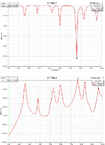
Fig. 4. (a) Simulated result of return loss for unslotted fractal UC-EBG (b) Simulated result of isolation for
Utilizing HFSS (High Frequency Structure Simulator) the proposed design of antenna has been simulated and
obtained some results. Three parameters are obtained which are return loss, frequency and radiation pattern by
simulation process of unslotted and u-slotted microstrip patch antenna with fractal UC-EBG structure.
Firstly, unslotted patch with UC-EBG is analyzed. In which, the simulation results at unslotted patch with UC-EBG
are performed by the two dielectric patches on the metallic substrate. In addition, the measured and simulated
results between the two port is better than -10dB with the return loss is -11.06dB in the frequency range of 7.6GHz.
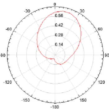
Fig 4. (a),(b) shows the results at S11,S21 and radiation pattern of unslotted microstrip patch with UC-EBG
structure.
Fig. 4. (c) Radiation pattern of unslotted fractal UC-EBG
U-shaped slot is cut in the microstrip patch antenna with UC-EBG structure at different return loss was obtained in
the fig.5 (a). The optimized U-slotted microstrip patch antenna resonant at 6 GHz and 9.2 GHz frequency with the
return loss is -10.61 dB and -15.57 dB respectively in the fig 5(b).
(b)
Fig. 5. (a) Simulated result of return loss for unslotted fractal UC-EBG(b) Simulated isolation of the unslotted
fractal UC-EBG
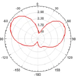
Fig. 5(c). Radiation pattern for U-slotted MSA
Fig 5(a),(b),(c)shows the results at S11,S21 and radiation pattern of U-slotted MSA with UC-EBG structure. The
proposed UC-EBG with unslotted and U-slotted MSA can be easily integrated with the C and X band applications.
3. CONCLUSION
A fractal UC-EBG structures and three cross slots are based on the Moore space filling curves has been designed.
The antenna array is compact size due to the column of the fractal UC-EBG structure. Moreover the design of
U-slot microstrip patch antenna is presented in this paper. The unslotted patch antenna is single band antenna and
resonant at 7.6 GHz frequency with -10 dB bandwidth. By making U-slot in the patch, dual band response of
antenna is achieved and performance of antenna also improved. The optimized U-slotted microstrip patch antenna
resonant at frequencies 6 GHz and 9.2 GHz with -10 dB bandwidth respectively. The results show that the
comparing of unslotted and U-slotted patch with UC-EBG to obtain the C and X band frequencies.
REFERENCES
[2] Swaraj panusa, Mithilesh kumar, “Design and analysis of triple band F-slot microstrip patch antenna”,
International journal of computer applications=s, vol04, Oct 2014.
[3] Shilpak. Jose, Dr.S.Suganthi “rectangular microstrip patch antenna for wireless applications”, IEEE 2015.
[4] C.A.Balanis “Antenna Theory, Analysis and Design”, John wiley & sons Inc.u.k. 2013.
[5] Bind K.Kanajia, sachinkumar, Mukeshk.khandelwal and A.K.Gautham “Single feed L-slot microstrip
patch antenna for circular polarization”, springer 2015.
[6] “Isolation enhancement in Microstrip patch antenna arrays”, I.Malar tamil prabha, R.Gayathri,
IJOOTS-2014.
[7] “Hexagonal shaped slotted microstrip patch antenna’, Tanjgarge IJESC 2016.
[8] “Isolation enhancement in patch antenna array with fractal UC-EBG structure and cross slot”, Xuyang,
Yingliu, seniormember, IEEE, Yun-Xuexu & shu-xigong, Member, I EEE 2017.
[9] “Design and simulation Eu slot position of rectangular microstrip patch antenna for broadband
applications” G.Aswankumar, I.B.A.Sarath 2016 IJESC.
[10] “Numerical analysis of slot position of rectangular U-slot microstrip patch antenna” Harleenkaur,