e-ISSN: 2278-7461, p-ISSN: 2319-6491
Volume 7, Issue 10 [October 2018] PP: 01-16
Effect of Brake Oil Pressure on the Performance of Conventional
and Modified Disc Brake at Different Initial Operating
Temperatures
Ibrahim Ahmed
1, Khaled abdelwahed
1and Mostafa M. Makrahy
2 1. Automotive Technology Department, Faculty of Industrial Education, Helwan University, Cairo, Egypt.2.Automotive Engineering Department, Faculty of Engineering, Minia University, Minia, Egypt.
Corresponding Author:Ibrahim Ahmed
ABSTRACT:
This paper presents an experimental study to examine the effect of brake oil pressure on the performance of the conventional and modified disc brake at different initial operating temperatures by using a brake test rig. This test rig has been recently designed and constructed at the Automotive Laboratory, Helwan University, Egypt. At first, the test rig is designed and constructed to examine the performance of the brake system. Second, a modification of the conventional disc brake is presented. After that, some experimental tests are conducted on the conventional and modified disc brake at different brake oil pressure at constant sliding speed and at different initial operating temperatures. Finally, comparison between conventional and modified disc brake are performed. Experimental results indicate that the modified disc brake can amplify the mean brake force and mean friction coefficient of the conventional disc brake at the same conditions.--- Date of Submission: 27-12-2018 Date of acceptance:12-01-2019 ---
I.
INTRODUCTION
The wheel vehicle brakes are classified generally into two main types of friction brakes namely, drum and disc brakes. The main function of friction brakes is to stop the vehicle or retard the vehicle velocity by converting the kinetic energy of the vehicle into thermal energy through the friction process between the brake pad or brake shoes and disc or drum.
During the repetitive brake process in the vehicles, the temperature of the rotating disc can reachto(200-250℃) and 300℃ for the brake pad [1]. The high temperatures of the rotating disc and brake pads causing a decrease in the shear strength of the brake pads and hence decrease in brake force causing “brake fade”[2]. Brake fade is loss in braking force at high temperatures (300-400 ℃) because of reduction in coefficient of friction, and this leads to decrease the braking effectiveness [3]. Furthermore, high temperatures of the disc brake components are responsible for most problems in vehicle braking system, such as increasing wear, judder and noise. The brake force and friction coefficient play an important role in brake system performance, and both of them are affected by different conditions such as the surface finishing, the type of friction material, temperature of the brake system components, rotational speed of the rotating disc, water and brake oil pressure. This leads to observation that the brake force and the coefficient of friction fluctuate with the braking time [4].
II.
TEST RIG DESCRIPTION
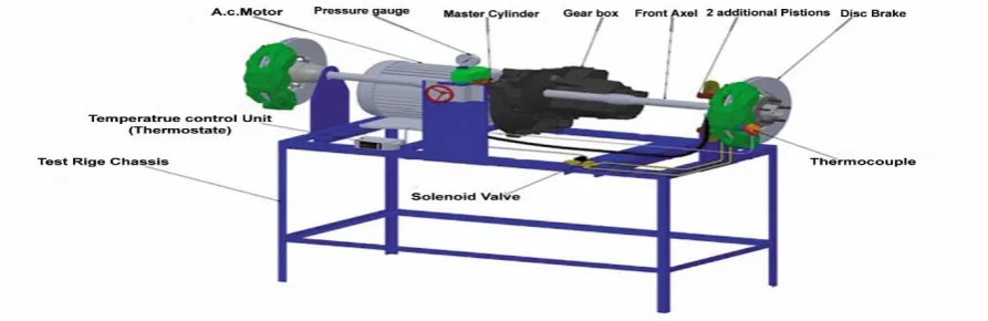
The brake test rig has two main objectives. The first objective is the ability to measure the generated brake power of the conventional and modified disc brake at all operating parameters. The second objective of the test rig is to generate the required kinetic energy that could be overcome by the braking system. The test rig is designed and constructed to achieve these requirements. Fig.1 shows the main components of the test rig which are: conventional and modified disc brake system assembly, components of generation the kinetic energy and the components of generation the normal force.
Figure (1) Main components of the test rig.
2.1 Conventional disc brake assembly
A disc brake of Hyundai Excel passenger car is used in the test rig. This braking system is a floating caliper disc brake. The main components of this system are shown in Fig.2. It consists of floating caliper with its slave cylinder which contains a hydraulic piston of diameter 5.3cm, rotor disc, two brake pads, wheel bearing, finger and hub. The hydraulic pipe is connected between the master cylinder and the hydraulic piston.
Figure (2) Conventional disc brake of Hyundai Excel.
2.2 Modified disc brake assembly
Figure (3) Modified disc brake.
Fig.4 shows the assembly of one of the two additional pistons with the caliper of the conventional disc brake by using steel bracket. One of the two brackets is connected to both of the first additional piston via two steel screw M10and the caliper via the guide pin of the caliper. The other brackets also are connected to both of the second additional piston via two steel screw M10 and the caliper via the guide bolt of the caliper.
Figure (4) Assembly of an additional piston with the caliper.
2.3 Kinetic energy generation
An A.C electric motor is used in the test rig, as shown in Fig. (1). The electric motor is three phase type which has maximum power 10 Hp at 1500 r.p.m.In order to do the experiments at various speeds, a gear box with differential unit of a Hyundai Excel passenger car is installed between the electric motor and the brake system. This gear box and its differential unit have reduction ratios of 6.5, 3.9, 2.6, 1.9, 1.5 and a reverse reduction ratio of 6.8.
2.4 Normal force generation
Figure (5) Normal force generation assembly.
III.
MEASUREMENT INSTRUMENTATION
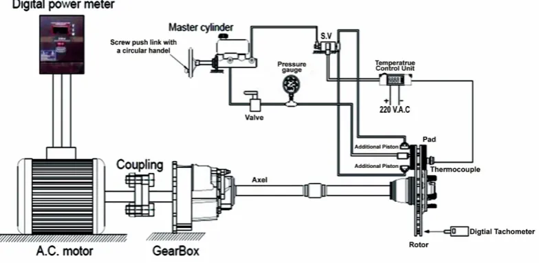
The measurement instrumentations system which are used can be divided as following: Pressure measurement and normal force calculation, Speed measurement, Brake torque, brake force and coefficient of friction calculation and temperature measurement, as shown schematically in Fig. (6).
Figure (6) Schematic sketch of the test rig and measurement instrumentation.
3.1 Pressure measurement and normal force calculation
The value of the oil pressure in the brake system is measured by using an oil pressure gauge as shown in Fig(6). The pressure gauge is mounted in the hydraulic line between the master cylinder and the slave cylinder of the brake system. The normal force of the conventional system is calculated as the multiplication of the piston area of the slave cylinder and the magnitude of the oil pressure. Different values of the normal forces of the conventional system are determined according to the values of the oil pressure as shown in the equations below:
As = π4Ds2 (1) P = Fn .c
As (2)
Fn.c = P∗ As (3) Where:
Ds The piston diameter of the slave cylinder equals (0.053 m ) As The piston area of the slave cylinder equals (2.2*10−3 m2 )
Fn.c The normal force of the conventional system which affects the brake pad.
well as constant normal force.The normal force of the modified system is calculated as shown in the equations below:
Fn.m = p∗(As+ 2Ad) (4) Where:
Fn.m The normal force of the modified system that affects the brake pad.
Ad The cross-section area of one of the two additional pistons, equals 2.5*10−4 m2 Ad= π4d2 (5)
d The diameter length of the additional piston, equals 1.8 cm
According to equation (4) the values of the oil pressure of 2.5, 5, 7.5 and 10 bar produce normal force of values 675, 1350, 2025 and 2700 N respectively for the modified system.
3.2 Brake torque calculation and speed measurement
In this work the brake power is measured by using digital power meter as shown in Fig (6). The type of the digital power meteris Schneider PM 1200 which has range from 20 watt to 300 k.watt and has an accuracy 1% of reading for power and gives 60 readings per minute.The power meter measured the power of the electric motor during the braking process as the normal force affected the brake pad. It also measured the no load power as there was no normal force affected the brake pad. The no load power is the power which consumed from the electric motor to overcome the inertia forces of the test rig elements. In this study the brake power was determined asfollow:
Pb = PL− Pno (6) Where:
PbThe brake power (watt)
PLThe electric motor power during the braking process (watt)
PnoThe electric motor power during the operation at no braking load (watt)
The rotational speed of the rotor disc (sliding speed) is also a very significant parameter in the braking process. The sliding speed of the braking system was measured by a digital tachometer which its type is (DT2234 ) and it has range from 5 to 100000 r.p.m with accuracy of 0.5 %. The first aim of measuring the sliding speed of the braking system was to calculate the angular speed of the rotating disc which was used with brake power to calculate the brake torque. The second aim was to know the behavior of the brake system with different sliding speeds.
By calculating the brake power of the braking system during the braking process as mentioned in equation (6) and the angular speed of the rotating disc, the brake torque was calculated as follow:
Tb = Pωb (7)
ω= 260πn (8) Where:
Tb The braking torque (N.m)
ω The angular speed of the rotating disc (rad/sec.) n The sliding speed of the rotating disc (r.p.m)
Four sliding speeds of the rotating disc are selected during the tests. These values were 50, 100, 150 and 200 r.p.m.
3.3 Brake force and friction coefficient calculations
The brake force and friction coefficient are most important parameters indicate the performance of both conventional and modified disc brake at high temperatures in this work. For conventional and modified disc brake, by calculating the brake torque as mentioned in equation (7) the braking force of the conventional and modified system can be calculated as follow:
Tb = Fb . reff (9)
For a disc brake system there is a pair of brake pads, thus the total brake torque is : Tb = 2 Fbreff (10)
reff = ro+ r2 i (11) Where:
Fb The brake force generated at the contact interface (N) reff The effective radius of the brake pad, equals 0.089 m ro The outer radius of the brake pad (m)
ri The inner radius of the brake pad(m)
From equation (10) the brake force of the conventional and modified system can be calculated as follow: Fb.c = 2 rTb.c
Fb.m = 2 rTb.m
eff (13)
Where: Fb.cThe brake force of the conventional system (N) Fb.m The brake force of the modified system (N) Tb.c The brake torque of the conventional system (N.m) Tb.m The brake torque of the modified system (N.m) However the braking force is dependent upon the normal force and the friction coefficient, which is derived as below: Fb= µ Fn (14)
The generated normal force of the conventional and modified system was determined based on the brake-line pressure (P) as mentioned in equations (3) and (4), then by substituting equations (3) and (4) into equation (14), the coefficient of friction of the conventional and modified system can be calculated as follow: Fb.c =µc P As (15)
Fb.m = µm P (As+ 2Ad) (16)
µc= FPAb.cs (17)
µm = P(AFsb.m+2Ad) (18) Where:
µc The friction coefficient of the conventional system.
µm The friction coefficient of the modified system.
3.4 Temperature measurement
The effect of the initial operating temperature is considered during this work to investigate its effect on the performance of the conventional and modified system. A thermocouple of J-type was selected and is fixed in the brake pad to measure the friction temperature at the contact area between the brake disc and the brake pad. The output signal of the thermocouple was sent to the temperature control unit (thermostat). The temperature control unit is adjusted at a certain temperature. As the brake pad temperature reaches to the adjusted temperature of the control unit, in this case the temperature control unit sends an electrical signal to the coil of the solenoid valve. So the pressurized brake oil passes through the solenoid valve to the two additional pistons. Four initial operating temperature are selected during the tests. These values were 50, 100,150 and 200 ℃. Figure (7) shows the temperature measurement instrumentation.
Figure (7) Temperature measurement instrumentation.
IV.
RESULTS AND DISCUSSION
The experimental work is carried out to investigate the effect of brake oil pressure at constant speed and at different initial operating temperatures on the brake force and friction coefficient of the conventional and modified disc brake. All experimental tests are conducted in the same conditions 60 seconds of braking.The brake power was measured every second by the digital power meter. The sliding speed, the brake oil pressure and the initial operating temperature were measured during each test for the conventional and modified disc brake. The brake force and friction coefficient of the conventional and modified disc brake were calculated every second and plotted with the brake time during each test.
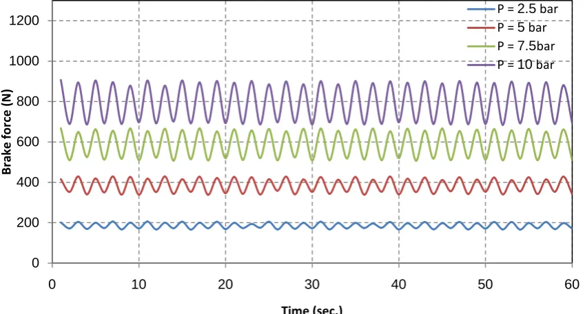
forces of the conventional and modified system are increased with increasing the brake oil pressure. The increase with the modified system is greater than with the conventional system. The brake forces of the conventional and modified system fluctuate with no identical trend at each constant pressure with the brake time. The fluctuation of the brake force is due to the variation of the friction coefficient with the time. The presented results in Fig. (10) show that, the increase of the brake oil pressure leads to increase the mean brake force of the conventional and modified system, but the mean brake force of the modified system is higher than the mean brake force of the conventional system at each pressure. This is because the normal force which affects the brake pad of the modified system is greater than the normal force which affects the brake pad of the conventional system at the same pressure. The mean brake forces of the conventional system are 186, 384, 587, 793N and the mean brake forces of the modified system are 230, 479, 732, 987N at brake oil pressure of 2.5, 5, 7.5 and 10 bar respectively. At each constant pressure, the value of the mean brake force of the modified system increases by 23 %, 24%, 24%, 24% respectively over the value of the mean brake force of the conventional system.
The presented results in Fig. (11) show the effect of the brake oil pressure on the mean friction coefficient of the conventional and modified system at sliding speed of 200 r.p.m and initial temperature 50℃. The results indicated that, the increase of the oil pressure cause an increase of the mean friction coefficient of the conventional and modified system. Also,the mean friction coefficient of the modified system is higher than the mean friction coefficient of the conventional system at each pressure. This is because the normal force which affects the brake pad of the modified system is greater than the normal force which affects the brake pad of the conventional system at the same pressure.
Figure (8) Variation of brake force of the conventional system as a function of time at sliding speed 200 rpm and initial temperature 50℃ at different brake oil pressure.
0 200 400 600 800 1000 1200
0 10 20 30 40 50 60
Br
ak
e f
or
ce
(N
)
Time (sec.)
P = 2.5bar
P = 5bar
P = 7.5bar
Figure (9) Variation of brake force of the modified system as a function of time at sliding speed 200 rpm and initial temperature 50℃ at different brake oil pressure.
Figure (10) Effect of pressure on the mean brake force of the conventional and modified system at sliding speed 200 rpm and initial temperature 50 ℃.
0 200 400 600 800 1000 1200 1400 1600
0 10 20 30 40 50 60
Br
ak
e f
or
ce
(N
)
Time (sec.)
P = 2.5bar
P = 5bar
P = 7.5bar
P = 10bar
0 200 400 600 800 1000 1200
2.5 5 7.5 10
M
ea
n b
ra
ke
fo
rc
e
(N
)
Pressure (N/m2)
Fb.c
Figure (11) Effect of brake oil pressure on the mean friction coefficient of the conventional and modified system at sliding speed 200 rpm and initial temperature 50℃.
4.2 Effect of brake oil pressure at sliding speed 200 rpm and initial temperature 100℃
Fig. (12) and Fig. (13) illustrate the effect of the brake oil pressure on the brake force of the conventional and modified system at sliding speed 200 r.p.m and initial temperature 100 ℃ . The results showed that, the increase of the brake oil pressure cause an increase of the brake forces of the conventional and modified system. The increase with the modified system is greater than with the conventional system. The effect of the brake oil pressure on the mean brake force of the conventional and modified system is shown in Fig. (14). The results showed that, the mean brake forces of the conventional and modified system are increased with increasing the brake oil pressure. Also the mean brake force of the modified system is greater than the mean brake force of the conventional system at each pressure.The mean brake forces of the conventional system are 181, 379, 578, 781 N and the mean brake forces of the modified system are 225, 474, 723, 976N at brake oil pressure of 2.5, 5, 7.5 and 10 bar respectively. At each constant pressure, the value of the mean brake force of the modified system increases by 24%, 25%, 25%, 24% respectively over the value of the mean brake force of the conventional system. Fig.(15) shows the variation of the mean friction coefficient of the conventional and modified system at sliding speed 200 r.p.m and initial temperature 100℃ at different brake oil pressure. The presented results in this Fig. showed that, the mean friction coefficient of the conventional and modified system are increased with increasing the brake oil pressure. Also the mean friction coefficient of the modified system is higher than the mean friction coefficient of the conventional system at each pressure. This isbecause the normal force which affects the brake pad of the modified system is greater than the normal force which affects the brake pad of the conventional system at the same pressure.
Figure(12) Variation of brake force of the conventional system as a function of time at sliding speed 200 r.p.m and initial temperature 100℃ at different brake oil pressure.
0.3 0.31 0.32 0.33 0.34 0.35 0.36 0.37
0 2.5 5 7.5 10
M
ea
n f
ric
tio
n
co
ef
fic
ien
t
Pressure (N/m2)
µ.c µ.m
0 200 400 600 800 1000 1200
0 10 20 30 40 50 60
Br
ak
e f
or
ce
(N
)
Time (sec.)
P = 2.5bar
P = 5bar
P = 7.5bar
Figure (13) Variation of brake force of the modified system as a function of time at sliding speed 200 r.p.m and initial temperature 100℃ at different brake oil pressure.
Figure (14) Effect of brake oil pressure on the mean brake force of the conventional and modified system at sliding speed 200 r.p.m and initial temperature 100 ℃.
0 200 400 600 800 1000 1200 1400
0 10 20 30 40 50 60
Br
ak
e f
or
ce
(N
)
Time (sec.)
P = 2.5bar
P = 5bar
P = 7.5bar
P = 10bar
0 200 400 600 800 1000 1200
2.5 5 7.5 10
M
ea
n
bra
ke
fo
rc
e
N
Pressure (N/m2)
Fb.c
Figure (15) Effect of brake oil pressure on the mean friction coefficient of the conventional and modified system at sliding speed 200 r.p.m and initial temperature 100 ℃.
4.3 Effect of brake oil pressure at sliding speed 200 rpm and initial temperature 150℃
At sliding speed 200 r.p.m and initial temperature 150℃, the effect of the brake oil pressure on the brake force of the conventional and modified system is shown in Fig. (16) and Fig. (17). The results indicated that, the increase of the brake oil pressure cause an increase of the brake force of the conventional and modified system.Also, the results showed that, with the increase of the braking time at the initial operating temperature 150℃, the brake force of the conventional and modified system tend to decrease specially at high pressure. Due to the increase of the braking time, the friction temperature increases and become over 150 ℃. Hence, the brake force tends to decrease as a result of friction coefficient decrease. The presented results in Fig. (18) show the effect of the brake oil pressure on the mean brake force of the conventional and modified system. The results showed that, the increase of the brake oil pressure leads to increase the mean brake force of the conventional and modified system. Also,the mean brake force of the modified system is higher than the mean brake force of the conventional system at each pressure. The mean brake forces of the conventional system are 131, 277, 432, 590 Nand the mean brake forces of the modified system are 171, 372, 577, 784 Nat brake oil pressure of 2.5, 5, 7.5 and 10 bar respectively. At each constant pressure, the value of the mean brake force of the modified system increases approximately by 30 %, 34%, 33%, 32%respectively over the value of the mean brake force of the conventional system. Fig. (19) illustrate the effect of the brake oil pressure on the mean friction coefficient of the conventional and modified system at sliding speed 200 r.p.m and initial temperature 150 ℃. The results indicated that, the increase of the oil pressure cause an increase of the mean friction coefficient of the conventional and modified system. Also, the mean friction coefficient of the modified system is higher than the mean friction coefficient of the conventional system at each pressure. The increase of the oil pressure from 2.5 to 10 bar causes an increase on the mean friction coefficient from 0.238to 0.268 for conventional system and from 0.253 to 0.29 for the modified system.
0.3 0.31 0.32 0.33 0.34 0.35 0.36 0.37
0 2.5 5 7.5 10
M
ea
n f
ric
tio
n
co
ef
fic
ien
t
Pressure (N/m2 )
µ.c
Figure (16) Variation of brake force of the conventional system as a function of time at sliding speed 200 r.p.m and initial temperature 150℃ at different brake oil pressure.
Figure (17) Variation of brake force of the modified system as a function of time at sliding speed 200 r.p.m and initial temperature 150℃ at different brake oil pressure.
Figure (18) Effect of brake oil pressure on the mean brake force of the conventional and modified system at sliding speed 200 r.p.m and initial temperature 150 ℃.
0 100 200 300 400 500 600 700 800 900 1000
0 10 20 30 40 50 60
Br ak e f or ce (N ) Time (sec)
P = 2.5bar
P = 5bar
P = 7.5bar
P = 10bar
0 200 400 600 800 1000 1200
0 10 20 30 40 50 60
Br ak e f or ce (N ) Time (sec)
P = 2.5bar
P = 5bar
P = 7.5bar
P = 10bar
0 100 200 300 400 500 600 700 800 900
2.5 5 7.5 10
M ea n b ra ke fo rc e (N )
Pressure (N/m2)
Figure (19) Effect of brake oil pressure on the mean friction coefficient of the conventional and modified system at sliding speed 200 r.p.m and initial temperature 150℃.
4.4 Effect of brake oil pressure at sliding speed 200 rpm and initial temperature 200℃
The effect of brake oil pressure on the brake forces of the conventional and modified system at sliding speed 200 r.p.m and initial temperature 200 ℃ is presented in Fig. (20) and Fig. (21). The results showed that, the brake forces of the conventional and modified system are increased with increasing the brake oil pressure. The presented results also indicatedthat, with the increase of the braking time at the initial temperature of 200 ℃, the brake force of the conventional and modified system tend to decrease specially at high pressure. Due to the increase of the braking time, the friction temperature increases and become over 200℃. Hence, the brake force tends to decrease as a result of friction coefficient decrease. The presented results in Fig. (22) show the effect of the brake oil pressure on the mean brake force of the conventional and modified system. The results showed that, the mean brake forces of the conventional and modified system are increased with increasing the brake oil pressure. Also, the mean brake force of the modified system is greater than the mean brake force of the conventional system at each pressure. The mean brake forces of the conventional system are 113, 237, 366, 500 N and the mean brake forces of the modified system are 153, 331.7, 511, 693 N at brake oil pressure of 2.5, 5, 7.5and 10bar respectively. At each constant pressure, the value of the mean brake force of the modified system increases by 35%, 39%, 39%, 38% respectively over the value of the mean brake force of the conventional system.
Figure (23) shows the variation of the mean friction coefficient of the conventional and modified system at sliding speed 200 r.p.m and initial temperature 200 ℃ at different brake oil pressure. The presented results in this Figure showed that, the mean friction coefficient of the conventional and modified system are increased with increasing the brake oil pressure. Also Fig. (23) shows that, the mean friction coefficient of the modified system is higher than the mean friction coefficient of the conventional system at each pressure. This is because the normal force which affects the brake pad of the modified system is greater than the normal force which affects the brake pad of the conventional system at the same pressure. This leads to increase the mean friction coefficient of the modified system at each pressure. The increase of the oil pressure from 2.5 to 10 bar causes an increase on the mean friction coefficient from 0.205 to o.227 for conventional system and from 0.227 to 0.256 for the modified system.
0 0.05 0.1 0.15 0.2 0.25 0.3 0.35
0 2.5 5 7.5 10
M
ea
n f
ric
tio
n
co
ef
fic
ien
t
Pressure (N/m2)
µ.c
Figure (20) Variation of brake force of the conventional system as a function of time at sliding speed 200 r.p.m and initial temperature of 200 ℃ at different brake oil pressure.
Figure (21) Variation of brake force of the modified system as a function of time at sliding speed of 200 r.p.m and initial temperature of 200℃ at different brake oil pressure.
Figure (22) Effect of brake oil pressure on the mean brake force of the conventional and modified system at sliding speed 200 r.p.m and initial temperature 200 ℃.
0 100 200 300 400 500 600 700 800
0 10 20 30 40 50 60
Br ak e f or ce (N ) Time (sec)
P = 2.5bar
P = 5bar
P = 7.5bar
P = 10bar
0 100 200 300 400 500 600 700 800 900 1000
0 10 20 30 40 50 60
Br ak e f or ce (N ) Time (sec.)
P = 2.5bar
P = 5bar
P = 7.5bar
P = 10bar
0 100 200 300 400 500 600 700 800
2.5 5 7.5 10
M ea n b ra ke fo rc e (N )
Pressure (N/m2)
Figure (23) Effect of brake oil pressure on the mean friction coefficient of the conventional and modified system at sliding speed 200 r.p.m and initial temperature 200 ℃.
V.
CONCLUSION
The main conclusions from the present study can be summarized in the following points:
1- The brake force of the conventional and modified system varies and fluctuate with no identical trend with the brake time. This is due to the variation of the friction coefficient with the brake time. It tend to decrease with the brake time at the initial operating temperature 150℃ and 200℃. Which gives an indication of the brake fade with increase of temperature.
2- The increase of the brake oil pressure increases the mean brake force of the conventional and modified system.
3- The increase of the brake oil pressure of values 2.5, 5, 7.5, 10 bar respectively at initial operating temperature 50℃ and sliding speed 200 rpm increases the mean brake forces of the modified system by 23%, 24%, 24%, 24% respectively over the values of the of the mean brake forces of the conventional system. Also, the increase of the brake oil pressure at initial temperature 100℃ and sliding speed 200 rpm increases the mean brake forces of the modified system by 24%, 25%, 25%, 24% respectively over the values of the mean brake forces of the conventional system.
4- The increase of the brake oil pressure of values 2.5, 5, 7.5, 10 bar respectively at initial temperature 150℃ and sliding speed 200rpm increases the mean brake forces of the modified system by 30%, 34%, 33%, 32% respectively over the values of the mean brake forces of the conventional system. While the increase of the brake oil pressure at initial temperature 200℃ and sliding speed 200 rpm increases the mean brake forces of the modified system by 35%, 39%, 39%, 38% respectively over the values of the mean brake forces of the conventional system.
5- The increase of the brake oil pressure at constant sliding speed 200r.p.m and at different initial operating temperatures 50, 100, 150, 200℃ increases the mean friction coefficient of the conventional and modified system. But at each pressure the mean friction coefficient of the modified system was higher than the mean friction coefficient of the conventional system.
6- The increase of the initial operating temperature decreases the mean brake force of the conventional and modified system.
7- The increase of the initial operating temperature from 50℃ to 100℃ at different brake oil pressure (2.5bar:10 bar) and sliding speed 200 rpm decreases the mean brake force of the conventional and modified system by (2% : 3%). But the increase of the initial operating temperature from 50℃ to 150℃ at different brake oil pressure (2.5bar:10bar) and sliding speed 200 rpm decreases the mean brake force of the conventional and modified system by (26% : 30%) and (21% : 26%) respectively.
8- The increase of the initial operating temperature from 50℃ to 200℃ at different brake oil pressure (2.5bar:10bar) and sliding speed 200rpm decreases the mean brake force of the conventional and modified system by (37%:40%) and (30% : 34%) respectively.
0 0.05 0.1 0.15 0.2 0.25 0.3
0 2.5 5 7.5 10
M
ea
n f
ric
tio
n
co
ef
fic
ien
t
Pressure (N/m2)
µ.c
REFERENCES
[1]. Mikael Eriksson,FilipBergman,Staffan Jacobson, “On the nature of tribological contact in automotive brake”, Wear 252 (2002), pp.26-36.
[2]. H.Jang.K.Ko,S.J.Kim,R.H.Basch, “The effect of metal fibers on the friction performance of automotive brake friction materials”, Wear 256 (2004), pp.406-414.
[3]. J. Bijwe,Nidhi,N. Majumdar,B.K.Satapathy, “Influence of modified phenolic resins of the fade and recovery behavior of friction materials”, Wear 259 (2005), pp.1068-1078.
[4]. NoubyM.Ghazaly et al “A Preliminary Experimental Investigation of a New Wedge Disc Brake”, Int. Journal of Engineering Research and Application, ISSN :2248-9622,vol.3, Issue 6, Nov-Dec 2013, pp.735-744.
[5]. Ouyang, H.,Nack, W.V.,Yuan, Y.and Chen, F. “Numerical analysis of automotive disc brake squeal: a review”, Int. J Vehicle Noise and Vibration, vol. 1, Nos.3-4, pp.207-230,2005.
[6]. Nouby M., Abdo J., Mathivanan D. and Srinivasan k. “Evaluation of Disc Brake Materials for Squeal Reduction”, Tribology Transactions, 54: 644-656, 2011.
[7]. Nouby M., andSrinivasan k., “Simulation of structural modifications of a disc brake system to reduce brake squeal”, Proc. IMechE, Part D: J. Automobile Engineering, vol. 225, No. 5, 2011, 653-672.
[8]. Dunlap, K. B., Riehle, M. A. and Longhouse, R. E. “An investigation overview of automotive disc brake noise”, SAE paper 1999-01-0142.
[9]. Bergman, F., Eriksson, M. and Jacobson, S. “Influence of disc topography on generation of brake squeal”, Wear, pp.225-229, 1999. [10]. Cunefare, K. A. and Graf, A. J. “Experimental active control of automotive disc brake rotor squeal using dither”, Journal of Sound
and Vibration, Vol. 250, No. 4, pp. 575-590, 2002.
[11]. James, S. “An experimental study of disc brake squeal”, PhD Thesis, Department of Engineering, University Liverpool, May 2003. [12]. Nouby M. Ghazaly “Study on Automotive Disc brake Squeal Using Finite Element Analysis and Design of Experiments” PhD.
Thesis, Department of Mechanical Engineering, Anna University, India, 2011.
[13]. Fieldhouse, J. D., Steel, W.P., Talbot, C.J. and Siddiqui, M.A. “Brake noise reduction using rotor asymmetric”, Proc. Of IMechE International conference Braking 2004, professional Engineering Publishing Ltd,pp.209-222,2004.
[14]. Triches, M. J., Samir, N. Y., and Jordan, R. “Reduction of squeal noise from the disc brake system using constrained layer damping”, J. of the Brazilian Society of Mechanical Science and Engineering, vol. 26, pp. 340-348, 2004.
[15]. Chen T. F., “Relationship between Formulation and Noise of phenolic Resin Matrix Friction Lining Tested In Acoustic Chamber on Automotive Brake Dynamometer”, Master of Science Thesis, Southern Illinois University, 2005.
[16]. Amr M. M. Rabia, Noubi M. Ghazaly, M. M. Salem, Ali M. Abd-El-Twawab. “An Experimental Study of Automotive Disc Brake Vibrations”. Int. Journal of Engineering and Science (IJES), 2013, vol.2, Issue 01, pp. 194-200.