Multi Directional Solar Tracking System
S.Sri Saran
1, P.S.V.N.Srinivas
2, D.S.A.R.Varshini
3, K.Veerarajamma
4and R.B.K.Raju
51B.Tech, Electrical and Electronic Department, Pragati Engineering College, India. Email: [email protected] 2B.Tech, Electrical and Electronic Department, Pragati Engineering College, India. Email: [email protected] 3B.Tech, Electrical and Electronic Department, Pragati Engineering College, India. Email: [email protected] 4B.Tech, Electrical and Electronic Department, Pragati Engineering College, India. Email: [email protected] 5B.Tech, Electrical and Electronic Department, Pragati Engineering College, India. Email: [email protected]
Article Received: 13 July 2017 Article Accepted: 26 July 2017 Article Published: 28 July 2017
1.INTRODUCTION
The continuous growth of global energy demand and the environmental concern about the global warming, fossil fuel exhaustion and the need to reduce the carbon dioxide emission has to lead the exploration of renewable energy sources. As compared to other renewable energy sources photovoltaic energy has great advantages like cleanliness, no noise and very less maintenance. PV systems have been extensively used for low power electrical generation and have applications such as electrification for domestic applications, water pumping and air condition in rural and isolated areas. It is very difficult to establish a new utility system in rural areas because of cost and maintenance consideration. So DC micro grid can be directly used for rural requirements and solar energy can be utilized to generate power. The installed power can be increased by adding panels, which is one of the most attractive features of PV systems. The low conversion efficiency of PV module and the variation of the output power due to changes in atmospheric conditions such as solar irradiation and temperature variation, requires specific control technique to ensure maximum power point operation in order to harvest maximum power from each module. A DC-DC BOOST converter with high voltage gain is employed to step up the output DC voltage from the PV module to a high voltage level without losing the overall efficiency of the system. Energy conversion is most efficient when the rays fall perpendicularly onto the solar panels. Thus, the work is divided into three main parts namely the mounting system, the tracking controller system and the electrical power system. In solar tracking systems, solar panels are mounted on a structure which moves to track the movement of the sun throughout the day. There are two mediums of tracking, electrical and mechanical tracking. In the both the methods respective components are used with different strategies to get the maximum power output. There are three methods of tracking: active, passive and chronological tracking, but
maximum power tracking gives the maximum output power from the panel there by giving the maximum efficiency from the panel.
1.1 Solar Power
Solar cells made of silicon absorb the sun's radiation, also called photovoltaic cells. The photovoltaic process involves the movement and displacement of electrons to absorb the sun's radiation and create electricity, but there are also solar systems that use large scale mirrors to heat water, or produce high temperatures and generate steam, which is used to turn a generator.
1.2 Solar Panel
The working principle of all today solar cells is essentially the same. It is based on the photovoltaic effect. In general, the photovoltaic effect means the generation of a potential difference at the junction of two different materials in response to visible or other radiation. The basic processes behind the photovoltaic effect are:
1. Generation of the charge carriers due to the absorption of photons in the materials that form a junction,
2. Subsequent separation of the photo-generated charge carriers in the junction,
3. Collection of the photo-generated charge carriers at the terminals of the junction.
In general, a solar cell structure consists of an absorber layer, in which the photons of incident radiation are efficiently absorbed resulting in the creation of electron-hole pairs. In order to separate the photo-generated electrons and holes from each other, the so-called “semi-permeable membranes” are attached to the both sides of the absorber. The important requirement for the semi-permeable membranes is that they selectively allow only one type of charge carrier to pass through. An important issue for designing an efficient solar A B S T R A C T
This paper deals with the design and execution of a solar tracker system dedicated to the PV conversion panels. The proposed Multi - directional solar tracker device ensures the optimization of the conversion of solar energy into electricity by properly orienting the PV panel in accordance with the real position of the sun. The operation of the experimental model of the device is based on a DC motor intelligently controlled by a drive unit that moves a mini PV panel according to the signals received from four simple but efficient light sensors. On detecting the maximum intensity of the sunlight the panel will rotate according to that direction, tracking maximum output power. The output power from the panel is fed to a boost converter and is stored in a rechargeable battery and supplied to the loads.
cell is that the electrons and holes generated in the absorber layer reach the membranes.
1.3 Maximum Power Point Tracking
Panel tracking - this is where the panels are on a mount that follows the sun. The most common are the Zome works and Watt sun. These optimize output by following the sun across the sky for maximum sunlight. These typically give you about a 15% increase in winter and up to a 35% increase in summer. This is just the opposite of the seasonal variation for MPPT controllers. Since panel temperatures are much lower in winter, they put out more power. And winter is usually when you need the most power from your solar panels due to shorter days. Maximum Power Point Tracking is electronic tracking -usually digital. The charge controller looks at the output of the panels, and compares it to the battery voltage. It then figures out what is the best power that the panel can put out to charge the battery. It takes this and converts it to best voltage to get maximum AMPS in to the battery. (Remember, it is Amps into the battery that counts).Power Point tracking enables PV module to change the direction initial from TOP to the direction of incident rays with the help of DC Motor through LDR’S which improves the efficiency of the module. All of these have built in MPPT. Efficiency is around 94% to 97% for the MPPT conversion on those.
1.4 Need for Solar Tracking
Global warming has increased the demand and request for green energy produced by renewable sources such as solar power. Consequently, solar tracking is increasingly applied as a sustainable power generating solution. Solar tracking system is a device for orienting a solar panel or concentrating solar reflector or lens towards the sun. Concentrators, especially in solar cell applications, required high degree of accuracy to ensure that the concentrated sunlight is directed precisely to the powered device. Precise tracking of sun is achieved through systems with single or dual axis. But with the existing single or dual axis the power is tracked up to some extent only. That’s why we are proposing the Quadruple axis solar tracking system to track the sunlight throughout the 3600.
Fig 1: Fixed Mount Solar System
2.EXISTINGSYSTEM
2.1 Fixed mount Solar System
Residential and small-capacity commercial or industrial rooftop solar project (kW) and solar water heater panels are usually fixed, often flush-mounted on an appropriately facing pitched roof. Advantages of fixed mount systems (i.e. factors tending to indicate against trackers) include the following: •Mechanical Advantages: Simple to manufacture, lower installation and maintenance costs.
•Wind-loading: It is easier and cheaper to provision a sturdy mount; all mounts other than fixed flush-mounted panels
must be carefully designed having regarded to wind loading due to greater exposure.
• Indirect light: approximately 10% of the incident solar radiation is diffusing light, available at any angle of misalignment with the Sun.
• Tolerance to misalignment: effective collection area for a flat-panel is relatively insensitive to quite high levels of misalignment with the Sun – see table and diagram at Accuracy Requirements section above – for example even a 25° misalignment reduces the direct solar energy collected by less than 10%.
Fixed mounts are usually used in conjunction with non-concentrating systems; however an important class of non-tracking concentrating collectors, of particular value in the 3rd world, is portable solar cookers. These utilize relatively low levels of concentration, typically around 2 to 8 Suns and are manually aligned. Fixed-mount solar may also be a good option due to geographic and citing constraints, such as soil type and system location.
2.2 Single Axis Tracking System
The panels can turn around the centre axis. In this single axis system the panels are fixed to a certain base and they turn only in single axis. The single-axis solar tracking system analyzed in the paper consist of a PV panel rotating around a tilted shaft under the action of a Bidirectional-DC Motor controlled according to the real sun position estimated by means of two light intensity sensors. The light sensor’s consists of two LDR’s placed on either side of the panel separated by an opaque plate.
Fig 2: Single Axis Tracking System
Depending on the intensity of the sun rays one of the two LDR’s will be shadowed and the other will be illuminated. According to the use of single-axis tracking can increase the electricity yield by as much as 27 to 32 percent. This kind of tracker is most effective at equatorial latitudes where the sun is more or less overhead at noon. Due to the annual motion of the earth the sun also moves in the right and left direction depending on the season and due to this the efficiency of single-axis is reduced since the single-axis tracker only tracks the movement of sun from top to bottom. During cloudy days the efficiency of the single axis tracker is almost close to the fixed panel.
3. PROPOSED SYSTEMS
to work at maximum power point. So that under any climatic conditions maximum power is extracted. This way we make efficient use of both solar panel and solar-energy from sun. There are different methods of tracking out the power form the panel as discussed above.
Fig 3: Block Diagram of Proposed System
As mentioned in above topic we came to know that the project concept aims at extracting maximum power from solar panel by using light sensors (LDR’S).And by the status of LDR’s the panel rotates with the help of 12V geared Motor in any direction and if the sunlight is more in any direction then it rotates to that direction.
The output from panel is drived to an DC-DC Boost Converter which is used to increase the voltage without change in current rating their by increasing the battery charging condition. Where the output is given to Battery which is used to drive loads in failure of supply and in day times from panel after boost converter.
Fig 4: Schematic Diagram
4. HARDWARE IMPLEMENTATION
As mentioned above that we extract power from solar panel by converting light energy into electrical energy which is pollution free. This is about utilizing power by our own generation and transmitting the excess of power to the grid or battery in over load conditions and utilizes the current from grid or battery in low load conditions economically. So this is our main components:
Solar Panel
Rechargeable Battery Micro Controller
Inverter D.C Load A.C Load
4.1 Solar panel
Solar chargers convert light energy into DC current. They are generally portable, but can also be fixed mount. Fixed mount solar chargers are also known as solar panels. Solar panels are often connected to the electrical grid, whereas portable solar chargers as used off-the-grid (i.e. cars, boats, or RVs). Although portable solar chargers obtain energy from the sun only, they still can (depending on the technology) be used in low light (i.e. cloudy) applications. Portable solar charger are typically used for trickle charging, although some solar charger (depending on the wattage), can completely recharge batteries. Solar panels (arrays of photovoltaic cells) make use of renewable energy from the sun, and are clean.
4.1.1 Crystalline Silicon Solar Panels
The creation of solar panels typically involves cutting crystalline silicon into tiny disks less than a centimeter thick. These thin, wafer-like disks are then carefully polished and treated to repair and gloss any damage from the slicing process. After polishing, dopants (materials added to alter an electrical charge in a semiconductor or photovoltaic solar cell) and metal conductors are spread across each disk. The conductors are aligned in a thin, grid-like matrix on the top of the solar panel, and are spread in a flat, thin sheet on the side facing the earth.
To protect the solar panels after processing, a thin layer of cover glass is then bonded to the top of the photovoltaic cell. After the bonding of protective glass, the nearly-finished panel is attached to a substrate by expensive, thermally conductive cement. The thermally conductive property of the cement keep the solar panel from becoming overheated; any leftover energy that the solar panel is unable to convert to electricity would otherwise overheat the unit and reduce the efficiency of the solar cells.
Despite these protective measures against the tendency of solar panels to overheat, it is vital that when installing a solar panel, additional steps should be taken to ensure the solar panel is kept cool. Elevating the solar panel above ground, to let the airflow underneath, will cool the device.
4.1.2 Amorphous Silicon Solar Panels
Amorphous silicon solar panels are a powerful that differ in output, structure and manufacture than traditional photo-voltaic which use crystalline silicon. Amorphous silicon solar cells, or A-si cells, are developed in a continuous roll-to-roll process by vapour-depositing silicon alloys in multiple layers, with each extremely thin layer specializing in the absorption of different parts of the solar spectrum. The result is record-breaking efficiency and reduced materials cost (A-si solar cells are typically thinner than their crystalline counterparts).
connected electrically and packaged into a frame (more commonly known as a solar panel), which can then be grouped into larger solar arrays.
Photovoltaic cells are made of special materials called semiconductors such as silicon, which is currently used most commonly. Basically, when light strikes the cell, a certain portion of it is absorbed within the semiconductor material. This means that the energy of the absorbed light is transferred to the semiconductor. The energy knocks electrons loose, allowing them to flow freely.
PV cells also all have one or more electric field that acts to force electrons freed by light absorption to flow in a certain direction. This flow of electrons is a current and by placing metal contacts on the top and bottom of the PV cell, the current can be drawn off for external use such as to power a calculator. This current, together with the cell's voltage (which is a result of its built-in electric field or fields), defines the power (or wattage) that the solar cell can produce.
4.2 Battery
An electrical battery is one or more electrochemical cells that convert stored chemical energy into electrical energy. The invention of the first battery (or "voltaic pile") was in 1800 by Alessandro Volta. Nowadays, batteries have become a common power source for many household and industrial applications. According to a 2005 estimate, the worldwide battery industry generates US$48 billion in sales each year, with 6% annual growth.
There are two types of batteries: primary batteries (disposable batteries), which are designed to be used once and discarded and secondary batteries (rechargeable batteries), which are designed to be recharged and used multiple times.
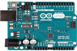
4.3 Arduino Board
Any microcontroller based board which follows the standard Arduino schematic and is flashed with the Arduino boot loader can be called an Arduino board. The Arduino is referred to as open source hardware, since the standard schematic is open to everyone and anybody can make their own version of Arduino board following the standard. Arduino is a single board microcontroller, intended to make the application of interactive objects or environments more accessible. The hardware consists of an open source hardware board designed around an 8-bit Atmel AVR microcontroller, or a 32-bit Atmel ARM. Pre-programmed into the on-board microcontroller chip is a boot-loader that allows uploading programs into the microcontroller memory without needing a chip /device programmer.
Fig 3: Arduino board
4.4 DC MOTOR
A DC motor relies on the fact that like magnet poles repels and unlike magnetic poles attracts each other. A coil of wire with a current running through it generates a electromagnetic field aligned with the center of the coil. By switching the current on or off in a coil its magnet field can be switched on or off or by switching the direction of the current in the coil the direction of the generated magnetic field can be switched 180°. A simple DC motor typically has a stationary set of magnets in the stator and an armature with a series of two or more windings of wire wrapped in insulated stack slots around iron pole pieces (called stack teeth) with the ends of the wires terminating on a commutator. The armature includes the mounting bearings that keep it in the centre of the motor and the power shaft of the motor and the commutator connections. The winding in the armature continues to loop all the way around the armature and uses either single or parallel conductors (wires), and can circle several times around the stack teeth. The total amount of current sent to the coil, the coil's size and what it's wrapped around dictate the strength of the electromagnetic field created. The sequence of turning a particular coil on or off dictates what direction the effective electromagnetic fields are pointed. By turning on and off coils in sequence a rotating magnetic field can be created. These rotating magnetic fields interact with the magnetic fields of the magnets (permanent or electromagnets) in the stationary part of the motor (stator) to create a force on the armature which causes it to rotate. In some DC motor designs the stator fields use electromagnets to create their magnetic fields which allow greater control over the motor. At high power levels, DC motors are almost always cooled using forced air.
The commutator allows each armature coil to be activated in turn. The current in the coil is typically supplied via two brushes that make moving contact with the commutator. Now, some brushless DC motors have electronics that switch the DC current to each coil on and off and have no brushes to wear out or create sparks.
Different number of stator and armature fields as well as how they are connected provides different inherent speed/torque regulation characteristics. The speed of a DC motor can be controlled by changing the voltage applied to the armature. The introduction of variable resistance in the armature circuit or field circuit allowed speed control. Modern DC motors are often controlled by power electronics systems which adjust the voltage by "chopping" the DC current into on and off cycles which have an effective lower voltage
4.5 SPUR GEAR - WORM GEAR ARRANGEMENT 4.5.1 Spur Gear
4.5.2 Worm Gear
A worm is meshed with a worm wheel, which looks similar to a spur gear. Worm-and-gear sets are a simple and compact way to achieve a high torque, low speed gear ratio. For example, helical gears are normally limited to gear ratios of less than 10:1 while worm-and-gear sets vary from 10:1 to 500:1. A disadvantage is the potential for considerable sliding action, leading to low efficiency.
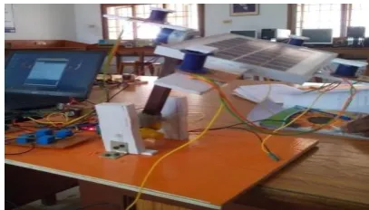
5.RESULT
The panel is tracked along all the directions with the help of LDR’s and the geared and gearless motors. As and when the sunlight is more in any direction the panel rotates in that direction in any direction.
Sun Ray’s Direction
Without
Tracking With Tracking
Top Output
Voltaeg:3.9V
Output Voltaeg:5.5V
Bottom Output
Voltaeg:2.8V
Output Voltaeg:5.1V
Right Output
Voltaeg:2V
Output Voltaeg:3.6V
Left Output
Voltaeg:1.6V
Output Voltaeg:2.4V
Table 1: Comparison of Solar Panel Output Ranges
When the LDR of the Right Side is high the panel rotates towards Right side tracking the sun.
Fig 4: Panel Rotating towards Right
When the LDR of the Left Side is high the panel rotates towards Left side tracking the sun.
Fig 5: Panel Rotating towards Left
When the LDR of the Top Side is high the panel rotates towards Top side tracking the sun.
Fig6: Panel Rotating towards Top
When the LDR of the bottom side is high the panel rotates towards bottom side tracking the sun.
6.CONCLUSION
The PV array output power delivered to a load can be maximized using MPPT control systems. It consists of a power conditioner to interface the PV output to the load. In this project, the system consists of a high-efficiency, Boost type dc/dc converter, and a microcontroller based unit which controls the dc/dc converter directly from the PV. And, in this scheme we implemented multi directional tracking which tracks the sun continuously. In case of failure of supply main supply can be connected to overcome the power interruption.
REFERENCES
[1] V. Meksarik, S.Masri, S.Taib, C.M.Hadzer, “Development of high efficiency boost converter for photovoltaic application”, National Power & Energy Conference (PECon) 2004 Proceedings, 2004.
[2] Chintan, S.S. and Solanki, C.s., “Experimental evaluation of V-trough PV concentrator system using commercial PV modules”, Solar Energy Materials and Solar cells, vol. 91, p.453, 2007.
[3] P.C. M. Bernardo, Z. M. A. Peixoto, L.V.B. Machado Neto, “A high efficient micro-controlled boost converter with maximum power point tracking for photovoltaic systems”, International Conference on Renewable Energies and Power Quality (ICREPQ’09) Spain, April2009.
[4] C. Sungur, “Multi-Axes Sun-Tracking System with PLC Control for Photovoltaic Panels in Turkey”, Renewable Energy, 34(2009), pp. 1119–1125.
[5] Xuesong Zhou, Daichun Sonng, Youjie Ma, Deshu Cheng “The Simulation and Design for MPPT of PV System Based on Incremental Conductance Method” WASE International Conference on Information Engineering (2010).
[7] C. S. Chin, P. Neelakantan, et al., “Fuzzy Logic Based MPPT for Photovoltaic Modules Influenced by Solar Irradiation and Cell Temperature,” UK Sim 13th International Conference on Modelling and Simulation, 2011.
[8] P. RatnaIka, M. Rifa’I “.Maximum Power Point Tracking Control for Photovoltaic Using Neural Fuzzy” International journal of Computer and Electrical Engineering, Vol.4 (1) (2011).
[9] ArashShafiei, Ahmadreza Momeni and Sheldon S. Williamson, “A Novel Photovoltaic Maximum Power Point Tracker for Battery Charging Applications,” IEEE, 2012.
[10] Kais I. Abdul-lateef, “A Low cost single-axis sun tracking system using PIC microcontroller”, Diyala Journal of Engineering Sciences, Vol. 05, No. 01, pp.65-78, June 2012.
[11] Sohan Lal, Rohtash Dhiman, Mr.S.K.Sinha “Analysis Different MPPT Techniques for Photovoltaic System” International Journal of Engineering and Innovative Technology (IJEIT) Volume 2, Issue 6, December 2012.
[12] Comparative Study of Maximum Power Point Tracking Algorithms: 10.1002/pip.459.
[13] Deepthi.S, Ponni.A, Ranjitha.R, R Dhanabal “Comparison of Efficiencies of Single-Axis Tracking System and Dual-Axis Tracking System with Fixed Mount”, International Journal of Engineering Science and Innovative Technology Volume 2, Issue 2, March 2013.
AUTHOR BIOGRAPHIES
S.Sri Saranis pursuing B.Tech in Department of Electrical and Electronics Engineering, Pragati Engineering College, surampalem, Peddapuram. His interest in study of Advancement of technology related in real life by using electrical topology.
P.S.V.N.Srinivas is pursuing B.Tech in Department of Electrical and Electronics Engineering, Pragati Engineering College, surampalem, Peddapuram. His interest in study of Advancement of technology related in real life by using electrical power generation.
D.S.A.R.Varshini is pursuing B.Tech in Department of Electrical and Electronics Engineering, Pragati Engineering College, surampalem, Peddapuram. His interest in study of Advancement of technology related in real life by using electrical transmission .
K.Veerrajamma is pursuing B.Tech in Department of Electrical and Electronics Engineering, Pragati Engineering College, surampalem, Peddapuram. His interest in study of Advancement of technology related in real life by using power electonics.
R.B.K.Raju is pursuing B.Tech in Department of Electrical and Electronics Engineering, Pragati Engineering College, surampalem, Peddapuram. His interest in study of Advancement of technology related in real life by using electrical drives.